EP1361380B1 - Dichteinrichtung - Google Patents
Dichteinrichtung Download PDFInfo
- Publication number
- EP1361380B1 EP1361380B1 EP20030004049 EP03004049A EP1361380B1 EP 1361380 B1 EP1361380 B1 EP 1361380B1 EP 20030004049 EP20030004049 EP 20030004049 EP 03004049 A EP03004049 A EP 03004049A EP 1361380 B1 EP1361380 B1 EP 1361380B1
- Authority
- EP
- European Patent Office
- Prior art keywords
- sealing arrangement
- tube
- gap
- hose
- arrangement according
- Prior art date
- Legal status (The legal status is an assumption and is not a legal conclusion. Google has not performed a legal analysis and makes no representation as to the accuracy of the status listed.)
- Expired - Lifetime
Links
- 238000007789 sealing Methods 0.000 title claims abstract description 39
- 239000011324 bead Substances 0.000 claims abstract description 11
- 230000002093 peripheral effect Effects 0.000 abstract 1
- 238000007373 indentation Methods 0.000 description 4
- 239000000463 material Substances 0.000 description 4
- 238000005187 foaming Methods 0.000 description 2
- 238000004519 manufacturing process Methods 0.000 description 2
- 230000004308 accommodation Effects 0.000 description 1
- 230000015572 biosynthetic process Effects 0.000 description 1
- 238000010276 construction Methods 0.000 description 1
- 230000001419 dependent effect Effects 0.000 description 1
- 230000008021 deposition Effects 0.000 description 1
- 230000002349 favourable effect Effects 0.000 description 1
- 239000012530 fluid Substances 0.000 description 1
- 239000006260 foam Substances 0.000 description 1
- 238000010097 foam moulding Methods 0.000 description 1
- 239000007788 liquid Substances 0.000 description 1
- 238000000034 method Methods 0.000 description 1
- 239000011541 reaction mixture Substances 0.000 description 1
- 125000006850 spacer group Chemical group 0.000 description 1
Images
Classifications
-
- B—PERFORMING OPERATIONS; TRANSPORTING
- B29—WORKING OF PLASTICS; WORKING OF SUBSTANCES IN A PLASTIC STATE IN GENERAL
- B29C—SHAPING OR JOINING OF PLASTICS; SHAPING OF MATERIAL IN A PLASTIC STATE, NOT OTHERWISE PROVIDED FOR; AFTER-TREATMENT OF THE SHAPED PRODUCTS, e.g. REPAIRING
- B29C33/00—Moulds or cores; Details thereof or accessories therefor
- B29C33/0038—Moulds or cores; Details thereof or accessories therefor with sealing means or the like
-
- B—PERFORMING OPERATIONS; TRANSPORTING
- B29—WORKING OF PLASTICS; WORKING OF SUBSTANCES IN A PLASTIC STATE IN GENERAL
- B29C—SHAPING OR JOINING OF PLASTICS; SHAPING OF MATERIAL IN A PLASTIC STATE, NOT OTHERWISE PROVIDED FOR; AFTER-TREATMENT OF THE SHAPED PRODUCTS, e.g. REPAIRING
- B29C44/00—Shaping by internal pressure generated in the material, e.g. swelling or foaming ; Producing porous or cellular expanded plastics articles
- B29C44/34—Auxiliary operations
- B29C44/35—Component parts; Details or accessories
- B29C44/351—Means for preventing foam to leak out from the foaming device during foaming
-
- F—MECHANICAL ENGINEERING; LIGHTING; HEATING; WEAPONS; BLASTING
- F16—ENGINEERING ELEMENTS AND UNITS; GENERAL MEASURES FOR PRODUCING AND MAINTAINING EFFECTIVE FUNCTIONING OF MACHINES OR INSTALLATIONS; THERMAL INSULATION IN GENERAL
- F16J—PISTONS; CYLINDERS; SEALINGS
- F16J15/00—Sealings
- F16J15/46—Sealings with packing ring expanded or pressed into place by fluid pressure, e.g. inflatable packings
-
- B—PERFORMING OPERATIONS; TRANSPORTING
- B29—WORKING OF PLASTICS; WORKING OF SUBSTANCES IN A PLASTIC STATE IN GENERAL
- B29K—INDEXING SCHEME ASSOCIATED WITH SUBCLASSES B29B, B29C OR B29D, RELATING TO MOULDING MATERIALS OR TO MATERIALS FOR MOULDS, REINFORCEMENTS, FILLERS OR PREFORMED PARTS, e.g. INSERTS
- B29K2105/00—Condition, form or state of moulded material or of the material to be shaped
- B29K2105/04—Condition, form or state of moulded material or of the material to be shaped cellular or porous
Definitions
- the invention is concerned with a sealing device for the gap between two adjacent machine parts, comprising at least one over a additional supporting body inflatable, elastically stretchable hose, which in a groove in the side wall of one of the machine parts can be inserted and the inflated to a gap on the opposite side of the groove limiting surface of the other machine part can be applied.
- Sealing devices of this type are used, for example, in foaming tools used in which the two tool halves of large expansion are. It is therefore difficult to seal the gap between the two made of hard materials mold halves after closing the mold close so tightly that the introduced in the liquid state Reaction mixture no longer escape and contaminate the environment can.
- a seal which is described in the preamble of the patent application type known from DE PS 196 15 055 and for securely closing the Gap between an opening of a house and one in the opening usable frame of a hard material, consisting of a in the Slit deployable and inflatable tube, the ends immediately lying next to each other, pulled radially inwards and there on hose nozzles are threaded over the compressed air can be fed.
- the hose is not inflatable.
- sealing hoses which at their two Ends on the outside surrounded by fittings made of a hard material are in their area at the same time a sealing function with respect to the Have sealing gap. At least one of the patches is with a line-shaped recess provided by the compressed air in the hose can be injected or can be discharged from it. This succeeds it, the bloated hose on its entire length with the to engage the opposite face of the mold and the Sealing gap to seal this length. On the immediate area of Fittings have no influence. There may therefore be leakage.
- the known sealing device is therefore not suitable for applications in which the sealing gap must be sealed over the entire length. For example, for the production of complex foam bodies in which also in the end of the sealing hoses a very accurate seal is to be achieved, a new solution is sought.
- the invention has for its object to provide a sealing device, which ensures a secure seal even at the hose ends.
- the Sealing should be as simple as possible in their construction, no require special production costs and be versatile.
- the solution of the task is carried out at a sealing device of The aforementioned type according to the invention in that at least one end of the hose is provided with a circumferential and engaging in its interior indentation, in which the support body is inserted on the inside and that the hose is also in the Area of invagination inflatable and after inflation on the whole Length of the groove can be applied to the other machine part.
- This new sealing device allows a formation of the sealing tube, in which the sealing tube ends no longer have to be angled, but the sealing tube end can straight up in the sealing groove up to whose end will be postponed.
- the inwardly inverted end is at a Pressurized compressed air to the support body.
- the outside lying part of the hose is outward along its entire length bloated and puts it sealingly against the opposite surface. Tails, like they are state of the art, are not needed.
- the indentation is carried out so that it ends in a bead, which faces the end of the hose in the installed state of the sealing device end face of the Supporting body in at least one adjacent to the gap, first Partial area overlaps axially.
- the bead is so placed in such a way that in the installed state of the sealing device it continues to axially overlap the end face in the first subregion as in a second portion not limiting the gap.
- the first Part of this area is at the sealed area of the other Machine part can be applied while the second portion of the groove bottom of the groove facing the first machine part which receives the hose.
- the Deposition of the second portion of the bead can be performed so far, that it springs back in the installed state of the sealing device behind the end face of the support body.
- the first tube in both radial and axial Direction is stretchable so that it is fully inflated to the surrounding him Machine parts can adapt.
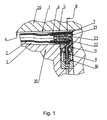
- FIG. 1 is enlarged in section the principal Structure of the sealing device shown.
- the sealing device should the gap. 1 between the adjacent machine parts 20 and 30 seal.
- Main component of the sealing device is the hose 2, which in the groove. 3 is inserted in the machine part 30.
- the tube 2 is not inflated State shown. Filled with compressed air is the hose 2 with his Outer wall on the walls of the groove 3 of the machine part 30 and at the Surface 4 of the machine part 20 at.
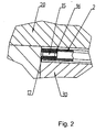
- Fig. 2 is a blind closure of a Hose end shown, while in Fig. 1, a hose end with a Compressed air supply is shown.
- the hose ends are inverted inside and in the indentations 6 and 16, respectively, a support body 5 and 15, respectively inserted. After the inflation of the tube 2, this puts his fully on his Boundary surfaces and it will be a complete seal on the reached the whole length.
- the hose ends lie with their beads 7 and 17 firmly on the machine part 30.
- the indentation 6 designed so that they are in a bead 7 ends, which in the adjacent to the machine part 20 Region 21 axially overlaps the support body 5. It is possible, as in FIG. 1 shown that the second portion 22 of the bead 7, the end face 8 of the Projecting body 5 surmounted.
- the different design of the bead 7 allows the introduction of the tube 9, which is connected to the support body 5.
- the support body 5 has in its interior a bore through which compressed air in the interior of the tube 2 can get.
- the support body 5 is here as Formed hose nozzle having the filling port 23.
- the tube 9 is in the Adapter 10 inserted, which is connected to a compressed air source.
- On the adapter 10 is a spacer 11, which the hose 2 before sharp edges and too much inflation protects.
- the support body 5 with the compressed air supply is slightly larger than that Support body 15.
- the choice of material for the support body or for the pipe or the Adapter 10 is dependent on the existing conditions on site. It is ensure that the hose 2 is inflated quickly and reliably and be emptied again after performing the foaming process of compressed air can.
Landscapes
- Engineering & Computer Science (AREA)
- Mechanical Engineering (AREA)
- General Engineering & Computer Science (AREA)
- Physics & Mathematics (AREA)
- Architecture (AREA)
- Fluid Mechanics (AREA)
- Sealing Devices (AREA)
- Pipe Accessories (AREA)
- Electric Vacuum Cleaner (AREA)
- Seal Device For Vehicle (AREA)
- Glass Compositions (AREA)
- Encapsulation Of And Coatings For Semiconductor Or Solid State Devices (AREA)
- Shaping Of Tube Ends By Bending Or Straightening (AREA)
- Gasket Seals (AREA)
Description
Claims (9)
- Dichteinrichtung für den Spalt (1) zwischen zwei benachbarten Maschinenteilen (20,30), umfassend zumindest einen über einen zusätzlichen Stützkörper (5) aufblasbaren, elastisch dehnbaren Schlauch (2), der in eine Nut (3) in der Seitenwand eines der Maschinenteile (30) einfügbar ist und der aufgeblasen an eine den Spalt (1) auf der der Nut (3) gegenüberliegenden Seite begrenzende Fläche des anderen Maschinenteils (20) anlegbar ist, dadurch gekennzeichnet, dass wenigstens ein Ende des Schlauches (2) mit einer umlaufenden und in seinen Innenraum eingreifenden Einstülpung (6, 16) versehen ist, in die der Stützkörper (5) innenseitig eingefügt ist und dass der Schlauch (2) auch im Bereich der Einstülpung (6,16) aufblähbar und nach dem Aufblasen auf der ganzen Länge der Nut (3) an das andere Maschinenteil (20) anlegbar ist.
- Dichteinrichtung nach Anspruch 1, dadurch gekennzeichnet, dass die Einstülpung (6, 16) in einem Wulst (7, 17) endet, der im Einbauzustand der Dichteinrichtung die diesem Ende zugewandte Stirnfläche (8) des Stützkörpers (5) in zumindest einem an den Spalt (1) angrenzenden ersten Teilbereich (21) axial übergreift.
- Dichteinrichtung nach einem der Ansprüche 1 oder 2, dadurch gekennzeichnet, dass der Wulst (7) im Einbauzustand der Dichteinrichtung die Stirnfläche (8) in dem ersten Teilbereich (21) axial weiter übergreift als in einem den Spalt (1) nicht begrenzenden zweiten Teilbereich (22).
- Dichteinrichtung nach einem der Ansprüche 1 bis 3, dadurch gekennzeichnet, dass der Wulst (7) im Einbauzustand der Dichteinrichtung in dem zweiten Teilbereich (22) hinter die dem Ende des Schlauches (2) zugewandte Stirnfläche (8) des Stützkörpers (5) zurückspringend ausgebildet ist.
- Dichteinrichtung nach einem der Ansprüche 1 bis 4, dadurch gekennzeichnet, dass der Stützkörper (5) als Schlauchtülle ausgebildet ist.
- Dichteinrichtung nach einem der Ansprüche 1 bis 5, dadurch gekennzeichnet, und dass die Schlauchtülle mit einem ihre Stirnfläche (8) überragenden Füllanschluss (23) versehen ist.
- Dichteinrichtung nach Anspruch 6, dadurch gekennzeichnet, dass der Füllanschluss ein Rohr (9) umfasst.
- Dichteinrichtung nach einem der Ansprüche 1 bis 6, dadurch gekennzeichnet, dass der Schlauch (2) innenseitig mit in Umfangsrichtung verteilten Rippen oder Nuten versehen ist.
- Dichteinrichtung nach einem der Ansprüche 1 bis 8, dadurch gekennzeichnet, dass der Schlauch (2) in radialer und in axialer Richtung dehnbar ist.
Applications Claiming Priority (2)
| Application Number | Priority Date | Filing Date | Title |
|---|---|---|---|
| DE10220842 | 2002-05-08 | ||
| DE2002120842 DE10220842B4 (de) | 2002-05-08 | 2002-05-08 | Dichteinrichtung |
Publications (3)
| Publication Number | Publication Date |
|---|---|
| EP1361380A2 EP1361380A2 (de) | 2003-11-12 |
| EP1361380A3 EP1361380A3 (de) | 2004-07-14 |
| EP1361380B1 true EP1361380B1 (de) | 2005-09-28 |
Family
ID=29225139
Family Applications (1)
| Application Number | Title | Priority Date | Filing Date |
|---|---|---|---|
| EP20030004049 Expired - Lifetime EP1361380B1 (de) | 2002-05-08 | 2003-02-25 | Dichteinrichtung |
Country Status (6)
| Country | Link |
|---|---|
| US (1) | US6953195B2 (de) |
| EP (1) | EP1361380B1 (de) |
| CN (1) | CN1300492C (de) |
| AT (1) | ATE305578T1 (de) |
| DE (2) | DE10220842B4 (de) |
| ES (1) | ES2251635T3 (de) |
Families Citing this family (11)
| Publication number | Priority date | Publication date | Assignee | Title |
|---|---|---|---|---|
| US7376879B2 (en) * | 2001-10-19 | 2008-05-20 | Interdigital Technology Corporation | MAC architecture in wireless communication systems supporting H-ARQ |
| US8018945B2 (en) | 2004-04-29 | 2011-09-13 | Interdigital Technology Corporation | Method and apparatus for forwarding non-consecutive data blocks in enhanced uplink transmissions |
| DE102004038114B4 (de) * | 2004-08-03 | 2008-08-28 | Frimo Group Gmbh | Dichteinrichtung für den Spalt zwischen zwei benachbarten, unnachgiebigen Maschinenteilen |
| AT8084U1 (de) | 2005-01-19 | 2006-01-15 | Alba Tooling & Engineering Gmb | Dichteinrichtung |
| DE102006015184A1 (de) * | 2006-04-01 | 2007-10-11 | Krauss-Maffei Kunststofftechnik Gmbh | Aufblasbare Dichtvorrichtung für ein Formwerkzeug |
| DE102007013450B3 (de) * | 2007-03-21 | 2008-09-04 | Frimo Group Gmbh | Dichteinrichtung für den Spalt zwischen zwei benachbarten, unnachgiebigen Maschinenteilen |
| EP2636905B1 (de) * | 2012-03-05 | 2015-07-08 | Sulzer Management AG | Dichtungsanordnung und Pumpe mit einer Dichtungsanordnung |
| DE102013006833B4 (de) * | 2013-04-22 | 2014-10-30 | Weiss Gwe Gmbh | Einrichtung und Verfahren zum Abdichten einer Begrenzungsöffnung sowie Arbeitsplatzanordnung mit der Einrichtung und Adapter dafür |
| DE102013214547A1 (de) * | 2013-07-25 | 2015-01-29 | Bayerische Motoren Werke Aktiengesellschaft | Flexibles Dichtelement mit variabler Versteifung |
| DE102015111078B4 (de) * | 2015-07-09 | 2017-09-14 | Kraussmaffei Technologies Gmbh | Schäumwerkzeug mit fahrbarem Dichtungsendstück |
| AT518180B1 (de) * | 2016-01-28 | 2017-08-15 | Alba Tooling & Eng Gmbh | Dichteinrichtung |
Citations (1)
| Publication number | Priority date | Publication date | Assignee | Title |
|---|---|---|---|---|
| DE19615055A1 (de) * | 1996-04-17 | 1997-10-23 | Bruno Winiger | Verfahren und Vorrichtung zum sicheren Verschließen von Öffnungen eines Hauses |
Family Cites Families (12)
| Publication number | Priority date | Publication date | Assignee | Title |
|---|---|---|---|---|
| US3749093A (en) * | 1971-08-10 | 1973-07-31 | S Bloom | Insertable device package |
| US3897088A (en) * | 1973-12-12 | 1975-07-29 | Amp Inc | Sealing boot |
| US3985365A (en) * | 1975-11-06 | 1976-10-12 | Bartholomew Thomas Catanzaro | Remotely actuated emergency shaft seal |
| NL7609734A (nl) * | 1976-09-01 | 1978-03-03 | Ihc Holland Nv | Afdichting voor de losopening van een hopper of dergelijke onderlosser. |
| DE3631875A1 (de) * | 1986-09-19 | 1988-04-07 | Continental Gummi Werke Ag | Endlosverbindung fuer schlaeuche von luftbereifungen |
| US4923223A (en) * | 1988-08-05 | 1990-05-08 | Plastic Specialties And Technologies Investments, Inc. | Kink impeding hose for spraying water |
| US5476268A (en) * | 1990-03-15 | 1995-12-19 | Unicraft Oy | Seal assembly with a hard seal layer actuated through a silicone layer |
| DE19645904A1 (de) * | 1996-11-07 | 1998-05-20 | Hausach Umformtechnik | Blähdichtring |
| DE19715293B4 (de) * | 1997-02-11 | 2005-06-02 | Johannes Schäfer vorm. Stettiner Schraubenwerke GmbH & Co. KG | Steckverbindung für Rohrleitungen |
| DE19708579C2 (de) * | 1997-03-03 | 1999-06-17 | Fritsche Moellmann Gmbh Co Kg | Dichteinrichtung |
| DE19916789C1 (de) * | 1999-04-15 | 2000-09-21 | Fritsche, Moellmann Gmbh & Co Kg | Dichtvorrichtung |
| DE20214798U1 (de) * | 2002-09-25 | 2003-01-16 | Heidel GmbH & Co KG, 49504 Lotte | Elastische aufblasbare Dichtungsschnur für Formwerkzeuge, insbesondere zur Herstellung von Fahrzeuginnenteilen |
-
2002
- 2002-05-08 DE DE2002120842 patent/DE10220842B4/de not_active Expired - Fee Related
-
2003
- 2003-02-25 DE DE50301241T patent/DE50301241D1/de not_active Expired - Lifetime
- 2003-02-25 ES ES03004049T patent/ES2251635T3/es not_active Expired - Lifetime
- 2003-02-25 AT AT03004049T patent/ATE305578T1/de active
- 2003-02-25 EP EP20030004049 patent/EP1361380B1/de not_active Expired - Lifetime
- 2003-04-28 CN CNB031224563A patent/CN1300492C/zh not_active Expired - Fee Related
- 2003-05-07 US US10/431,187 patent/US6953195B2/en not_active Expired - Lifetime
Patent Citations (1)
| Publication number | Priority date | Publication date | Assignee | Title |
|---|---|---|---|---|
| DE19615055A1 (de) * | 1996-04-17 | 1997-10-23 | Bruno Winiger | Verfahren und Vorrichtung zum sicheren Verschließen von Öffnungen eines Hauses |
Also Published As
| Publication number | Publication date |
|---|---|
| EP1361380A3 (de) | 2004-07-14 |
| US20040000764A1 (en) | 2004-01-01 |
| US6953195B2 (en) | 2005-10-11 |
| DE50301241D1 (de) | 2005-11-03 |
| ES2251635T3 (es) | 2006-05-01 |
| ATE305578T1 (de) | 2005-10-15 |
| CN1300492C (zh) | 2007-02-14 |
| DE10220842B4 (de) | 2005-06-16 |
| DE10220842A1 (de) | 2004-05-13 |
| EP1361380A2 (de) | 2003-11-12 |
| CN1456829A (zh) | 2003-11-19 |
Similar Documents
| Publication | Publication Date | Title |
|---|---|---|
| DE69733800T2 (de) | Vorrichtung und Kartusche für einen umstülpbaren Schlauchbeutel | |
| DE69701633T2 (de) | Abdichtung eines spaltes zwischen einer leitung und der dazugehörigenden rohrauskleidung | |
| EP2924322B1 (de) | Dichtungsvorrichtung | |
| DE10220842B4 (de) | Dichteinrichtung | |
| DE1475683A1 (de) | Kupplungsdichtring | |
| EP0533999B1 (de) | Verfahren zum Abdichten von Kanalrohren | |
| EP3011220B1 (de) | System und verfahren zum vortreiben eines rohrverbunds | |
| EP3376087B1 (de) | Verschraubbarer abzweig für ein unebenheiten aufweisendes kanalrohr | |
| EP3741469A1 (de) | Mehrkammerkartusche und verfahren zu ihrer befüllung | |
| EP3491254B1 (de) | Kolbeneinheit eines hydraulikzylinders | |
| EP0801015B1 (de) | Dichtungssystem | |
| DE2452221A1 (de) | Arbeitszylinder | |
| EP1640646B1 (de) | Dichteinrichtung | |
| EP3139079B1 (de) | Bausatz zur sanierung eines rohrleitungsanschlusses eines dickwandigen rohrs | |
| DE4114902A1 (de) | Absperrvorrichtung | |
| DE2059905C2 (de) | Verfahren und Vorrichtung zum Absperren des Strömungswegs in einer unter Druck stehenden Rohrleitung | |
| DE9412355U1 (de) | Absperrvorrichtung für Rohrleitungen zum Transport von flüssigen oder gasförmigen Medien | |
| DE29806603U1 (de) | Dichtelement zur Abdichtung von Rohrleitungen | |
| DE102015204799A1 (de) | Dichtungsvorrichtung | |
| DE3542048C2 (de) | ||
| DE4101531A1 (de) | Vorrichtung zum auffinden und abdichten von lecks in rohren | |
| DE69615152T2 (de) | Werkzeug zum automatischen Formen, an Kunststoffrohren, von Muffen grosser Länge | |
| DE9202199U1 (de) | Packer mit aufblasbaren Dichtelementen zur Abstützung an einer Rohrwandung | |
| DE1901669A1 (de) | Drehschiebersitz und Verfahren zu seiner Herstellung | |
| DE3345430C2 (de) |
Legal Events
| Date | Code | Title | Description |
|---|---|---|---|
| PUAI | Public reference made under article 153(3) epc to a published international application that has entered the european phase |
Free format text: ORIGINAL CODE: 0009012 |
|
| AK | Designated contracting states |
Kind code of ref document: A2 Designated state(s): AT BE BG CH CY CZ DE DK EE ES FI FR GB GR HU IE IT LI LU MC NL PT SE SI SK TR |
|
| AX | Request for extension of the european patent |
Extension state: AL LT LV MK RO |
|
| PUAL | Search report despatched |
Free format text: ORIGINAL CODE: 0009013 |
|
| AK | Designated contracting states |
Kind code of ref document: A3 Designated state(s): AT BE BG CH CY CZ DE DK EE ES FI FR GB GR HU IE IT LI LU MC NL PT SE SI SK TR |
|
| AX | Request for extension of the european patent |
Extension state: AL LT LV MK RO |
|
| 17P | Request for examination filed |
Effective date: 20040616 |
|
| 17Q | First examination report despatched |
Effective date: 20040917 |
|
| AKX | Designation fees paid |
Designated state(s): AT BE BG CH CY CZ DE DK EE ES FI FR GB GR HU IE IT LI LU MC NL PT SE SI SK TR |
|
| GRAP | Despatch of communication of intention to grant a patent |
Free format text: ORIGINAL CODE: EPIDOSNIGR1 |
|
| GRAS | Grant fee paid |
Free format text: ORIGINAL CODE: EPIDOSNIGR3 |
|
| GRAA | (expected) grant |
Free format text: ORIGINAL CODE: 0009210 |
|
| AK | Designated contracting states |
Kind code of ref document: B1 Designated state(s): AT BE BG CH CY CZ DE DK EE ES FI FR GB GR HU IE IT LI LU MC NL PT SE SI SK TR |
|
| PG25 | Lapsed in a contracting state [announced via postgrant information from national office to epo] |
Ref country code: IT Free format text: LAPSE BECAUSE OF FAILURE TO SUBMIT A TRANSLATION OF THE DESCRIPTION OR TO PAY THE FEE WITHIN THE PRESCRIBED TIME-LIMIT;WARNING: LAPSES OF ITALIAN PATENTS WITH EFFECTIVE DATE BEFORE 2007 MAY HAVE OCCURRED AT ANY TIME BEFORE 2007. THE CORRECT EFFECTIVE DATE MAY BE DIFFERENT FROM THE ONE RECORDED. Effective date: 20050928 Ref country code: NL Free format text: LAPSE BECAUSE OF FAILURE TO SUBMIT A TRANSLATION OF THE DESCRIPTION OR TO PAY THE FEE WITHIN THE PRESCRIBED TIME-LIMIT Effective date: 20050928 Ref country code: CZ Free format text: LAPSE BECAUSE OF FAILURE TO SUBMIT A TRANSLATION OF THE DESCRIPTION OR TO PAY THE FEE WITHIN THE PRESCRIBED TIME-LIMIT Effective date: 20050928 Ref country code: IE Free format text: LAPSE BECAUSE OF FAILURE TO SUBMIT A TRANSLATION OF THE DESCRIPTION OR TO PAY THE FEE WITHIN THE PRESCRIBED TIME-LIMIT Effective date: 20050928 Ref country code: SI Free format text: LAPSE BECAUSE OF FAILURE TO SUBMIT A TRANSLATION OF THE DESCRIPTION OR TO PAY THE FEE WITHIN THE PRESCRIBED TIME-LIMIT Effective date: 20050928 Ref country code: SK Free format text: LAPSE BECAUSE OF FAILURE TO SUBMIT A TRANSLATION OF THE DESCRIPTION OR TO PAY THE FEE WITHIN THE PRESCRIBED TIME-LIMIT Effective date: 20050928 Ref country code: FI Free format text: LAPSE BECAUSE OF FAILURE TO SUBMIT A TRANSLATION OF THE DESCRIPTION OR TO PAY THE FEE WITHIN THE PRESCRIBED TIME-LIMIT Effective date: 20050928 |
|
| REG | Reference to a national code |
Ref country code: GB Ref legal event code: FG4D Free format text: NOT ENGLISH |
|
| REG | Reference to a national code |
Ref country code: CH Ref legal event code: EP |
|
| REG | Reference to a national code |
Ref country code: IE Ref legal event code: FG4D Free format text: LANGUAGE OF EP DOCUMENT: GERMAN |
|
| REF | Corresponds to: |
Ref document number: 50301241 Country of ref document: DE Date of ref document: 20051103 Kind code of ref document: P |
|
| GBT | Gb: translation of ep patent filed (gb section 77(6)(a)/1977) |
Effective date: 20051111 |
|
| RAP2 | Party data changed (patent owner data changed or rights of a patent transferred) |
Owner name: FRIMO GROUP GMBH |
|
| PG25 | Lapsed in a contracting state [announced via postgrant information from national office to epo] |
Ref country code: DK Free format text: LAPSE BECAUSE OF FAILURE TO SUBMIT A TRANSLATION OF THE DESCRIPTION OR TO PAY THE FEE WITHIN THE PRESCRIBED TIME-LIMIT Effective date: 20051228 Ref country code: SE Free format text: LAPSE BECAUSE OF FAILURE TO SUBMIT A TRANSLATION OF THE DESCRIPTION OR TO PAY THE FEE WITHIN THE PRESCRIBED TIME-LIMIT Effective date: 20051228 Ref country code: GR Free format text: LAPSE BECAUSE OF FAILURE TO SUBMIT A TRANSLATION OF THE DESCRIPTION OR TO PAY THE FEE WITHIN THE PRESCRIBED TIME-LIMIT Effective date: 20051228 Ref country code: BG Free format text: LAPSE BECAUSE OF FAILURE TO SUBMIT A TRANSLATION OF THE DESCRIPTION OR TO PAY THE FEE WITHIN THE PRESCRIBED TIME-LIMIT Effective date: 20051228 |
|
| NLT2 | Nl: modifications (of names), taken from the european patent patent bulletin |
Owner name: FRIMO GROUP GMBH Effective date: 20051207 |
|
| PG25 | Lapsed in a contracting state [announced via postgrant information from national office to epo] |
Ref country code: MC Free format text: LAPSE BECAUSE OF NON-PAYMENT OF DUE FEES Effective date: 20060228 Ref country code: PT Free format text: LAPSE BECAUSE OF FAILURE TO SUBMIT A TRANSLATION OF THE DESCRIPTION OR TO PAY THE FEE WITHIN THE PRESCRIBED TIME-LIMIT Effective date: 20060228 Ref country code: BE Free format text: LAPSE BECAUSE OF NON-PAYMENT OF DUE FEES Effective date: 20060228 Ref country code: LU Free format text: LAPSE BECAUSE OF NON-PAYMENT OF DUE FEES Effective date: 20060228 |
|
| NLV1 | Nl: lapsed or annulled due to failure to fulfill the requirements of art. 29p and 29m of the patents act | ||
| PG25 | Lapsed in a contracting state [announced via postgrant information from national office to epo] |
Ref country code: HU Free format text: LAPSE BECAUSE OF FAILURE TO SUBMIT A TRANSLATION OF THE DESCRIPTION OR TO PAY THE FEE WITHIN THE PRESCRIBED TIME-LIMIT Effective date: 20060329 |
|
| REG | Reference to a national code |
Ref country code: ES Ref legal event code: FG2A Ref document number: 2251635 Country of ref document: ES Kind code of ref document: T3 |
|
| REG | Reference to a national code |
Ref country code: IE Ref legal event code: FD4D |
|
| ET | Fr: translation filed | ||
| PLBE | No opposition filed within time limit |
Free format text: ORIGINAL CODE: 0009261 |
|
| STAA | Information on the status of an ep patent application or granted ep patent |
Free format text: STATUS: NO OPPOSITION FILED WITHIN TIME LIMIT |
|
| 26N | No opposition filed |
Effective date: 20060629 |
|
| PG25 | Lapsed in a contracting state [announced via postgrant information from national office to epo] |
Ref country code: CH Free format text: LAPSE BECAUSE OF NON-PAYMENT OF DUE FEES Effective date: 20070228 Ref country code: LI Free format text: LAPSE BECAUSE OF NON-PAYMENT OF DUE FEES Effective date: 20070228 |
|
| REG | Reference to a national code |
Ref country code: CH Ref legal event code: PL |
|
| BERE | Be: lapsed |
Owner name: FRIMO GROUP G.M.B.H. & CO. Effective date: 20060228 |
|
| PG25 | Lapsed in a contracting state [announced via postgrant information from national office to epo] |
Ref country code: EE Free format text: LAPSE BECAUSE OF FAILURE TO SUBMIT A TRANSLATION OF THE DESCRIPTION OR TO PAY THE FEE WITHIN THE PRESCRIBED TIME-LIMIT Effective date: 20050928 |
|
| PG25 | Lapsed in a contracting state [announced via postgrant information from national office to epo] |
Ref country code: TR Free format text: LAPSE BECAUSE OF FAILURE TO SUBMIT A TRANSLATION OF THE DESCRIPTION OR TO PAY THE FEE WITHIN THE PRESCRIBED TIME-LIMIT Effective date: 20050928 |
|
| PG25 | Lapsed in a contracting state [announced via postgrant information from national office to epo] |
Ref country code: CY Free format text: LAPSE BECAUSE OF FAILURE TO SUBMIT A TRANSLATION OF THE DESCRIPTION OR TO PAY THE FEE WITHIN THE PRESCRIBED TIME-LIMIT Effective date: 20050928 |
|
| REG | Reference to a national code |
Ref country code: FR Ref legal event code: PLFP Year of fee payment: 14 |
|
| REG | Reference to a national code |
Ref country code: FR Ref legal event code: PLFP Year of fee payment: 15 |
|
| REG | Reference to a national code |
Ref country code: FR Ref legal event code: PLFP Year of fee payment: 16 |
|
| PGFP | Annual fee paid to national office [announced via postgrant information from national office to epo] |
Ref country code: GB Payment date: 20220218 Year of fee payment: 20 Ref country code: DE Payment date: 20220215 Year of fee payment: 20 Ref country code: AT Payment date: 20220218 Year of fee payment: 20 |
|
| PGFP | Annual fee paid to national office [announced via postgrant information from national office to epo] |
Ref country code: FR Payment date: 20220222 Year of fee payment: 20 Ref country code: ES Payment date: 20220301 Year of fee payment: 20 |
|
| REG | Reference to a national code |
Ref country code: DE Ref legal event code: R071 Ref document number: 50301241 Country of ref document: DE |
|
| REG | Reference to a national code |
Ref country code: GB Ref legal event code: PE20 Expiry date: 20230224 |
|
| REG | Reference to a national code |
Ref country code: AT Ref legal event code: MK07 Ref document number: 305578 Country of ref document: AT Kind code of ref document: T Effective date: 20230225 |
|
| REG | Reference to a national code |
Ref country code: ES Ref legal event code: FD2A Effective date: 20230426 |
|
| PG25 | Lapsed in a contracting state [announced via postgrant information from national office to epo] |
Ref country code: GB Free format text: LAPSE BECAUSE OF EXPIRATION OF PROTECTION Effective date: 20230224 |
|
| PG25 | Lapsed in a contracting state [announced via postgrant information from national office to epo] |
Ref country code: ES Free format text: LAPSE BECAUSE OF EXPIRATION OF PROTECTION Effective date: 20230226 |