EP1361468A2 - Procédé d'autofocalisation pour un microscope et système associé de réglage de la focalisation - Google Patents
Procédé d'autofocalisation pour un microscope et système associé de réglage de la focalisation Download PDFInfo
- Publication number
- EP1361468A2 EP1361468A2 EP03100966A EP03100966A EP1361468A2 EP 1361468 A2 EP1361468 A2 EP 1361468A2 EP 03100966 A EP03100966 A EP 03100966A EP 03100966 A EP03100966 A EP 03100966A EP 1361468 A2 EP1361468 A2 EP 1361468A2
- Authority
- EP
- European Patent Office
- Prior art keywords
- microscope
- control device
- relative movement
- computer
- contrast value
- Prior art date
- Legal status (The legal status is an assumption and is not a legal conclusion. Google has not performed a legal analysis and makes no representation as to the accuracy of the status listed.)
- Withdrawn
Links
- 238000000034 method Methods 0.000 title claims abstract description 19
- 230000008859 change Effects 0.000 claims description 2
- 230000000977 initiatory effect Effects 0.000 claims 1
- 238000011156 evaluation Methods 0.000 abstract 1
- 230000006870 function Effects 0.000 description 17
- 238000005259 measurement Methods 0.000 description 7
- 230000008901 benefit Effects 0.000 description 5
- 230000009466 transformation Effects 0.000 description 5
- 230000008569 process Effects 0.000 description 3
- 238000004364 calculation method Methods 0.000 description 2
- 230000003993 interaction Effects 0.000 description 2
- 238000012067 mathematical method Methods 0.000 description 2
- 230000001131 transforming effect Effects 0.000 description 2
- 230000015572 biosynthetic process Effects 0.000 description 1
- 238000007689 inspection Methods 0.000 description 1
- 230000003287 optical effect Effects 0.000 description 1
- 238000001454 recorded image Methods 0.000 description 1
- 230000001360 synchronised effect Effects 0.000 description 1
Images


Classifications
-
- G—PHYSICS
- G02—OPTICS
- G02B—OPTICAL ELEMENTS, SYSTEMS OR APPARATUS
- G02B21/00—Microscopes
- G02B21/24—Base structure
- G02B21/241—Devices for focusing
- G02B21/244—Devices for focusing using image analysis techniques
Definitions
- the invention relates to an auto focus method for a microscope.
- the invention further relates to a system for adjusting the focus for a Microscope.
- the system relates to a microscope with an in a working position arranged lens and a microscope stage, wherein a relative movement in the z direction between the objective and the microscope stage can be generated, a camera that is connected to the microscope, to take pictures of an object, a microscope control device and a computer that has at least one connection to the microscope control device connected is.
- a microscope is included an automatic focus device disclosed.
- the microscope includes one Storage device for backing up the data from the lenses in the Use microscope.
- the tasks of the inspection body also include Movement of the microscope table (also: focusing table).
- There is a CCD element provided as an image recording device, one of which selected lens receives an image and along with one Computing unit determines the optimal focus position from the contrast. In the Determining the optimal degree of sharpness must the lens data of the current lens used are taken into account.
- the system disclosed here is not designed to keep the contrast values at a continuous in the z direction to determine the moving microscope stage.
- the object is achieved by a process which defines the characteristics of the Claim 1 includes.
- Another object of the invention is accordingly a system to set the focus for a microscope that automatically, focused quickly and reliably on a microscopic object.
- the system for adjusting the focus for a microscope with one in one Working position arranged lens and a microscope stage is such formed that a between the lens and the microscope stage Relative movement in the z direction can be generated.
- a camera provided, which may be in the form of a video camera. The The camera is connected to the microscope via the phototube, thus the Take pictures of the object.
- a microscope control device and a computer is provided which has at least one connection are interconnected.
- the computer includes a means of creation a trigger signal, the trigger signal after completion of each Image acquisition from the camera determining the current z position of the continuous relative movement triggers. This so determined z position stored in a memory in the microscope control device. to The values of the z position are determined from determining the optimal focus position the memory.
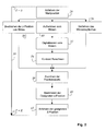
- Fig. 1 shows a schematic representation of a system 1 for adjustment the focus for a microscope 2.
- the system 1 comprises the microscope 2, a Microscope control device 4, a computer 6, in which a frame grabber (not shown) is installed and a display 8 with a keyboard 10.
- Das Microscope 2 consists of an automatic microscope (e.g. Leica DM LA) with the microscope control device 4.
- the microscope 2 and the Microscope control device 4 communicate via a special control cable 25.
- the structure of the microscope 2 is not described in detail received. Only those components of the microscope 2 are closer described, which are essential for the invention.
- the Microscope 2 consists of a stand 12 on which a nosepiece 14 is appropriate.
- the nosepiece 14 carries at least one objective 16.
- the Objective 16 in its working position is opposite a microscope stage 18 intended.
- the microscope stage 18 is in the x direction X, y direction Y and z direction Z movable. By creating a relative movement between the microscope stage 18 and the lens 16 in the working position Focus position changed or approached.
- a video camera 20 is attached to the microscope 2 in such a way that with the video camera 20 the image of the lens 16 imaged Object is recorded.
- the video camera 20 is via a video cable 21 connected to the computer 6.
- the video camera 20 Recorded signals are in the frame grabber in the computer 6 digitized.
- the computer 6 is connected to the via a first serial cable 22 Microscope control device 4 connected. Furthermore, the computer 6 is one second serial cable 24 connected to the microscope control device 4.
- the microscope control device 4 is used to control the automatic Functions of the microscope 2, e.g.
- the computer 6 and the microscope control device 4 communicate via the first serial Cable 22.
- the video camera 20 is on a photo tube 26 of the microscope 2 appropriate.
- the second serial cable 24 transmits trigger signals from Computer 6 for microscope control device 4. Release these signals Position determinations with the z-drive.
- the z-drive can either an adjustment of the microscope table 18 in the z direction or an adjustment of the lens 16 in the z direction.
- an adjustment of the z position means the adjustment of the microscope stage 18 in the z direction Z.
- the start position 26 is approached at the start of the focus function.
- r is the search area in the z direction Z, referred to as the focus capture area.
- the focus capture area is an interval around the ideal focus position.
- the computer 6 determines the contrast value of each on the basis of the image data Frame. When determining the contrast value, it is not necessary that the entire single image must be used. Usually enough it that you focus on a central one when determining contrast Part of the single image limited.
- a contrast calculation 34 is implemented in such a way that, for an image, they are parallel to the entry of the following picture is executed. The maximal Travel speed of the z-drive is selected so that from the Individual still significant contrast values can be obtained.
- the second serial cable 24 is sent to the microscope control device 4.
- the position values are assigned 38 to the respective ones Contrast values.
- the contrast values are a function of the z positions plotted ordinate plotted. They are made using a suitable one mathematical method a determination 40 of the appropriate Focus position (or z position). This z position eventually becomes Approaching the microscopic image.
- the start 42 is done by actuating the z-drive.
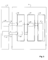
- Fig. 3 is the interaction of the computer 6 with the Microscope control device 4 shown.
- the focus measurement is based on Completion of each image acquisition generates a trigger signal from the computer 6, which on the part of the microscope control device 4 is immediate Determination of the instantaneous position of the z-drive (or the position of the Microscope stage 18).
- the trigger signal appears as Signal edge change on a handshake line of the second serial Cable 24 between the computer 6 and the microscope control device 4, and is from the microscope control device 4 on a modem status input 43 (e.g. CTS Clear-To-Send) of a serial interface IC UART 44 (Universal Asynchronous Receiver / Transmitter) registered.
- modem status input 43 e.g. CTS Clear-To-Send
- serial interface IC UART 44 Universal Asynchronous Receiver / Transmitter
- the UART 44 responds to the signal by triggering an external interrupt 46 a microcontroller 45 in the microscope control device 4, which for Control of the z-drive is responsible.
- the interrupt service routine then called determines the momentary position of the z-drive and writes the value in a data field 47 which is in a in the microscope control device 4 provided storage unit 48 is realized.
- the current position is stored in az position table in the storage unit 48.
- the Table index is increased by one after each write. This The process is repeated for all of the images in a focus measurement.
- part of the position data is transferred from the computer 6 the first serial cable 22 is retrieved and used to determine the focus position used.
- the first serial cable 22 is with a serial interface 41 of the computer 6 connected.
- the interface IC UART 44 has one further serial interface 49, via which the first serial cable 22 den Computer 6 connects to the microscope control device 4.
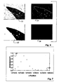
- the Roberts Cross image transformation generates with little computing effort a so-called gradient image from a gray image. Image regions appear in it with originally high contrast bright and those that focus on homogeneous image areas go back, dark.
- the gray values of the pixels are the amounts of the Gradients at the pixel locations of the original image.
- the Roberts cross operator consists of a first 2x2 filter core 50 and a second 2x2 filter core 51.
- the second 2x2 filter core 51 is rotated 90 ° with respect to the first 2x2 filter core 50.
- the rotation through 90 ° can be seen simply by comparing the first 2x2 filter core 50 with the second 2x2 filter core 51.
- the values in the fields of the first filter core 50 are shifted clockwise by one field each in the second 2x2 filter core 51.
- the first 2x2 filter core 50 is G x and the second 2x2
- Filter core 51 is denoted by G y .
- This value can be determined in one step with a pseudo operator 52 (see FIG. 5) can be determined.
- This pseudo-operator 52 has a low computing time takes up.
- the image transformation can be done by a computer current performance in a fraction of the video cycle time (time for taking a picture).
- a characteristic number K is obtained from each gradient image, which quantifies the contrast of the image, that is to say represents the contrast value of each image.
- the contrast value K the gray value frequency distribution of each gradient image is determined and stored in a data field H [1, 2, ..., N] .
- the image contrast K is determined, for example, for each gray image with 8 bit gray value resolution with:
- H [ i ] * i causes a stronger weighting of the higher gray values of the gradient image, the occurrence of which increases with increasing image sharpness.
- the level of i 0 can be adapted to the properties of the object to be focused on.
- K is normalized by division by N as the total number of pixels viewed or used for determining the focus.
- the interpolated focus position is determined mathematically the calculation routine as described in William H. Press (Editor), et al: NUMERICAL RECIPES IN C: THE ART OF SCIENTIFIC COMPUTING, Copyright (C) 1988-1992 by Cambridge University Press. Chapter 3.1, P.108.
- the routine delivers when specifying the coordinates of discrete Function points and any x value the associated y value of interpolated function.
- the x value stands for the z position of the Microscope optical 18 and the y value determined for the x value is the Contrast value.
Landscapes
- Physics & Mathematics (AREA)
- Engineering & Computer Science (AREA)
- Computer Vision & Pattern Recognition (AREA)
- Chemical & Material Sciences (AREA)
- Analytical Chemistry (AREA)
- General Physics & Mathematics (AREA)
- Optics & Photonics (AREA)
- Automatic Focus Adjustment (AREA)
- Microscoopes, Condenser (AREA)
Applications Claiming Priority (2)
| Application Number | Priority Date | Filing Date | Title |
|---|---|---|---|
| DE10217404A DE10217404A1 (de) | 2002-04-18 | 2002-04-18 | Autofokusverfahren für ein Mikroskop und System zum Einstellen des Fokus für ein Mikroskop |
| DE10217404 | 2002-04-18 |
Publications (2)
| Publication Number | Publication Date |
|---|---|
| EP1361468A2 true EP1361468A2 (fr) | 2003-11-12 |
| EP1361468A3 EP1361468A3 (fr) | 2003-12-17 |
Family
ID=28798558
Family Applications (1)
| Application Number | Title | Priority Date | Filing Date |
|---|---|---|---|
| EP03100966A Withdrawn EP1361468A3 (fr) | 2002-04-18 | 2003-04-10 | Procédé d'autofocalisation pour un microscope et système associé de réglage de la focalisation |
Country Status (4)
| Country | Link |
|---|---|
| US (1) | US7027221B2 (fr) |
| EP (1) | EP1361468A3 (fr) |
| JP (1) | JP2003315684A (fr) |
| DE (1) | DE10217404A1 (fr) |
Families Citing this family (39)
| Publication number | Priority date | Publication date | Assignee | Title |
|---|---|---|---|---|
| US7030351B2 (en) * | 2003-11-24 | 2006-04-18 | Mitutoyo Corporation | Systems and methods for rapidly automatically focusing a machine vision inspection system |
| US20050174085A1 (en) * | 2004-02-10 | 2005-08-11 | Olympus Corporation | Micromanipulation system |
| DE102004029912A1 (de) * | 2004-06-16 | 2006-01-05 | Carl Zeiss Jena Gmbh | Programmgesteuertes Mikroskop und Verfahren zur externen Steuerung von Mikroskopen |
| KR100866048B1 (ko) | 2005-10-24 | 2008-10-30 | 주식회사 케이엔제이 | 평면 보상 자동 초점장치 및 방법 |
| US7889264B2 (en) * | 2006-05-12 | 2011-02-15 | Ricoh Co., Ltd. | End-to-end design of superresolution electro-optic imaging systems |
| EP1986046B1 (fr) * | 2007-03-08 | 2014-07-16 | Cellavision AB | Procédé pour déterminer une position de mise au point et système de vision pour une inspection |
| KR100803046B1 (ko) * | 2007-03-28 | 2008-02-18 | 에스엔유 프리시젼 주식회사 | 비전 검사 시스템 및 이것을 이용한 피검사체의 검사 방법 |
| KR100863700B1 (ko) * | 2008-02-18 | 2008-10-15 | 에스엔유 프리시젼 주식회사 | 비전 검사 시스템 및 이것을 이용한 피검사체의 검사 방법 |
| US9865043B2 (en) | 2008-03-26 | 2018-01-09 | Ricoh Company, Ltd. | Adaptive image acquisition and display using multi-focal display |
| US9866826B2 (en) | 2014-11-25 | 2018-01-09 | Ricoh Company, Ltd. | Content-adaptive multi-focal display |
| US8897595B2 (en) * | 2008-03-26 | 2014-11-25 | Ricoh Co., Ltd. | Adaptive image acquisition for multiframe reconstruction |
| JP2010102196A (ja) * | 2008-10-24 | 2010-05-06 | Olympus Corp | 顕微鏡画像の自動調整方法、顕微鏡システム |
| US8111938B2 (en) * | 2008-12-23 | 2012-02-07 | Mitutoyo Corporation | System and method for fast approximate focus |
| US8111905B2 (en) * | 2009-10-29 | 2012-02-07 | Mitutoyo Corporation | Autofocus video tool and method for precise dimensional inspection |
| US8842174B2 (en) * | 2009-12-31 | 2014-09-23 | Abbott Point Of Care, Inc. | Method and apparatus for securing planar orientation of analysis chamber |
| JP2013516650A (ja) * | 2009-12-31 | 2013-05-13 | アボット ポイント オブ ケア インコーポレイテッド | 生物検体を高速フォーカス撮像する方法及び装置 |
| US9522396B2 (en) | 2010-12-29 | 2016-12-20 | S.D. Sight Diagnostics Ltd. | Apparatus and method for automatic detection of pathogens |
| DE102011075809A1 (de) * | 2011-05-13 | 2012-11-15 | Carl Zeiss Microimaging Gmbh | Verfahren und Vorrichtung zum Festlegen eines z-Bereiches in einer Probe, in dem ein z-Stapel der Probe mittels eines Mikroskops aufzunehmen ist |
| CN104169719B (zh) | 2011-12-29 | 2017-03-08 | 思迪赛特诊断有限公司 | 用于检测生物样品中病原体的方法和系统 |
| CN102706889B (zh) * | 2012-05-31 | 2015-08-12 | 东莞市新泽谷机械制造股份有限公司 | 料盘装卸方便的视觉检测设备 |
| EP2999988A4 (fr) | 2013-05-23 | 2017-01-11 | S.D. Sight Diagnostics Ltd. | Procédé et système d'imagerie de prélèvement cellulaire |
| IL227276A0 (en) | 2013-07-01 | 2014-03-06 | Parasight Ltd | A method and system for preparing a monolayer of cells, particularly suitable for diagnosis |
| US10831013B2 (en) | 2013-08-26 | 2020-11-10 | S.D. Sight Diagnostics Ltd. | Digital microscopy systems, methods and computer program products |
| US10482595B2 (en) | 2014-08-27 | 2019-11-19 | S.D. Sight Diagnostics Ltd. | System and method for calculating focus variation for a digital microscope |
| US9864205B2 (en) | 2014-11-25 | 2018-01-09 | Ricoh Company, Ltd. | Multifocal display |
| AU2016322966B2 (en) | 2015-09-17 | 2021-10-14 | S.D. Sight Diagnostics Ltd | Methods and apparatus for detecting an entity in a bodily sample |
| JP6563517B2 (ja) * | 2015-12-08 | 2019-08-21 | オリンパス株式会社 | 顕微鏡観察システム、顕微鏡観察方法、及び顕微鏡観察プログラム |
| US11733150B2 (en) | 2016-03-30 | 2023-08-22 | S.D. Sight Diagnostics Ltd. | Distinguishing between blood sample components |
| US11307196B2 (en) | 2016-05-11 | 2022-04-19 | S.D. Sight Diagnostics Ltd. | Sample carrier for optical measurements |
| EP3455626B1 (fr) | 2016-05-11 | 2025-08-06 | S.D. Sight Diagnostics Ltd. | Exécution des mesures optiques sur un échantillon |
| CN106767406B (zh) * | 2016-12-20 | 2022-08-16 | 华南理工大学 | 微纳定位系统及其对柔顺机构平台的全闭环在线控制方法 |
| US20190012782A1 (en) * | 2017-07-05 | 2019-01-10 | Integrated Vision Systems LLC | Optical inspection apparatus and method |
| AU2018369859B2 (en) | 2017-11-14 | 2024-01-25 | S.D. Sight Diagnostics Ltd | Sample carrier for optical measurements |
| AU2020372024B2 (en) | 2019-10-22 | 2026-03-12 | S.D. Sight Diagnostics Ltd | Accounting for errors in optical measurements |
| CN110727096B (zh) * | 2019-10-29 | 2022-03-18 | 北京临近空间飞行器系统工程研究所 | 一种显微镜对焦方法、装置及显微镜设备 |
| AU2020400400B2 (en) | 2019-12-12 | 2026-03-19 | S.D. Sight Diagnostics Ltd | Detecting platelets in a blood sample |
| BR112022011312A2 (pt) | 2019-12-12 | 2022-08-23 | S D Sight Diagnostics Ltd | Análise de um analito disposto dentro de um meio |
| MX2022007127A (es) | 2019-12-12 | 2022-07-11 | S D Sight Diagnostics Ltd | Generacion artificial de una imagen de frotis sanguineo en color. |
| CN112363309B (zh) * | 2020-11-13 | 2023-02-17 | 杭州医派智能科技有限公司 | 一种用于显微镜下病理图像的自动寻焦方法和系统 |
Family Cites Families (9)
| Publication number | Priority date | Publication date | Assignee | Title |
|---|---|---|---|---|
| CH504645A (de) | 1969-06-04 | 1971-03-15 | Ishikawajima Harima Heavy Ind | Olbrenner mit Schleuderscheibe |
| CH518562A (de) * | 1970-02-24 | 1972-01-31 | Zeiss Carl Fa | Verfahren und Vorrichtung zur automatischen Fokussierung von Mikroskopen |
| DE3475013D1 (en) | 1983-03-29 | 1988-12-08 | Olympus Optical Co | Microscope provided with automatic focusing device |
| DE3828381C2 (de) * | 1988-08-20 | 1997-09-11 | Zeiss Carl Fa | Verfahren und Einrichtung zur automatischen Fokussierung eines optischen Systems |
| US5932872A (en) * | 1994-07-01 | 1999-08-03 | Jeffrey H. Price | Autofocus system for scanning microscopy having a volume image formation |
| IL146882A0 (en) * | 1999-06-04 | 2002-08-14 | Janssen Pharmaceutica Nv | Robust autofocus system for a microscope |
| US6423960B1 (en) | 1999-12-31 | 2002-07-23 | Leica Microsystems Heidelberg Gmbh | Method and system for processing scan-data from a confocal microscope |
| DE20012874U1 (de) * | 2000-07-24 | 2000-10-26 | Fa. Carl Zeiss, 89518 Heidenheim | Beobachtungsvorrichtung |
| DE10127284A1 (de) * | 2001-06-05 | 2002-12-12 | Zeiss Carl Jena Gmbh | Autofokussiereinrichtung für ein optisches Gerät |
-
2002
- 2002-04-18 DE DE10217404A patent/DE10217404A1/de not_active Ceased
-
2003
- 2003-04-08 JP JP2003104149A patent/JP2003315684A/ja active Pending
- 2003-04-10 EP EP03100966A patent/EP1361468A3/fr not_active Withdrawn
- 2003-04-17 US US10/417,977 patent/US7027221B2/en not_active Expired - Fee Related
Also Published As
| Publication number | Publication date |
|---|---|
| JP2003315684A (ja) | 2003-11-06 |
| EP1361468A3 (fr) | 2003-12-17 |
| DE10217404A1 (de) | 2003-11-06 |
| US20030197925A1 (en) | 2003-10-23 |
| US7027221B2 (en) | 2006-04-11 |
Similar Documents
| Publication | Publication Date | Title |
|---|---|---|
| EP1361468A2 (fr) | Procédé d'autofocalisation pour un microscope et système associé de réglage de la focalisation | |
| EP2130087B1 (fr) | Procédé et dispositif d'analyse microscopique d'un échantillon, programme informatique et un produit programme informatique | |
| DE4000343C2 (de) | Automatische Fokussiervorrichtung | |
| DE102006011707B4 (de) | Verfahren und Vorrichtung zum Erzeugen einer strukturfreien fiberskopischen Aufnahme | |
| DE4113537C2 (de) | Vorrichtung zur automatischen Scharfeinstellung | |
| DE4235619C2 (de) | Entfernungsbestimmungseinrichtung für Automobile | |
| DE68921840T2 (de) | Bildaufnahme- und Verarbeitungseinrichtung. | |
| DE3931934C2 (de) | Bild-Ein/Ausgabevorrichtung | |
| DE3707487A1 (de) | Verfahren zur autofokussierung von mikroskopen und mikroskope mit einer autofokussierung | |
| DE10155884A1 (de) | Bildsuchvorrichtung | |
| DE102022109398A1 (de) | Autofokus-Verfahren und zugehöriges optisches Abbildungssystem | |
| DE102018104704A1 (de) | Digitales Mikroskop und Verfahren zum Verändern einer Vergrößerung eines digitalen Mikroskops | |
| DE60319095T2 (de) | Verfahren zur Verzerrungskorrektur von Multifokus-Bilderstapeln | |
| EP3692409A1 (fr) | Microscope confocal à grande résolution | |
| DE10143441A1 (de) | Verfahren und Mikroskopsystem zur Beobachtung dynamischer Prozesse | |
| DE60004667T2 (de) | Ausrichtbares autofokussystem | |
| DE69329741T2 (de) | Methode zur Positionskontrolle der Fokuslinse in einem Zoomobjektiv | |
| EP1548485B1 (fr) | Méthode de correction de la dérive d'un appareil optique | |
| DE3245675A1 (de) | Fokusdetektor | |
| DE19812599C2 (de) | Verfahren zur Video-Mikroskopie | |
| EP0803079A1 (fr) | Appareil photo avec dispositif de reglage d'objectif et de support d'image et procede de mise au point | |
| DE10018312C2 (de) | Verfahren und Vorrichtung zum Fokussieren eines Bildes | |
| EP0053263A2 (fr) | Méthode et dispositif pour trouver des concentrations de particules et en particulier des plaques de métaphases | |
| AT509970B1 (de) | Verfahren zur aufnahme von bildern von gegenständen | |
| DE69120455T2 (de) | Automatisches Fokussiergerät mit Verfahren zur optimalen Berechnung der Fokussierposition |
Legal Events
| Date | Code | Title | Description |
|---|---|---|---|
| PUAI | Public reference made under article 153(3) epc to a published international application that has entered the european phase |
Free format text: ORIGINAL CODE: 0009012 |
|
| PUAL | Search report despatched |
Free format text: ORIGINAL CODE: 0009013 |
|
| AK | Designated contracting states |
Kind code of ref document: A2 Designated state(s): AT BE BG CH CY CZ DE DK EE ES FI FR GB GR HU IE IT LI LU MC NL PT RO SE SI SK TR |
|
| AX | Request for extension of the european patent |
Extension state: AL LT LV MK |
|
| AK | Designated contracting states |
Kind code of ref document: A3 Designated state(s): AT BE BG CH CY CZ DE DK EE ES FI FR GB GR HU IE IT LI LU MC NL PT RO SE SI SK TR |
|
| AX | Request for extension of the european patent |
Extension state: AL LT LV MK |
|
| RIC1 | Information provided on ipc code assigned before grant |
Ipc: 7G 02B 21/24 B Ipc: 7G 02B 21/00 A |
|
| 17P | Request for examination filed |
Effective date: 20040527 |
|
| 17Q | First examination report despatched |
Effective date: 20040625 |
|
| AKX | Designation fees paid |
Designated state(s): CH DE FR GB LI |
|
| STAA | Information on the status of an ep patent application or granted ep patent |
Free format text: STATUS: THE APPLICATION IS DEEMED TO BE WITHDRAWN |
|
| 18D | Application deemed to be withdrawn |
Effective date: 20050923 |