EP1361966B2 - Toit de vehicule mobile - Google Patents
Toit de vehicule mobile Download PDFInfo
- Publication number
- EP1361966B2 EP1361966B2 EP02804173A EP02804173A EP1361966B2 EP 1361966 B2 EP1361966 B2 EP 1361966B2 EP 02804173 A EP02804173 A EP 02804173A EP 02804173 A EP02804173 A EP 02804173A EP 1361966 B2 EP1361966 B2 EP 1361966B2
- Authority
- EP
- European Patent Office
- Prior art keywords
- roof
- link
- vehicle
- kinematics
- vehicle roof
- Prior art date
- Legal status (The legal status is an assumption and is not a legal conclusion. Google has not performed a legal analysis and makes no representation as to the accuracy of the status listed.)
- Expired - Lifetime
Links
- 230000006835 compression Effects 0.000 claims description 4
- 238000007906 compression Methods 0.000 claims description 4
- 230000008878 coupling Effects 0.000 claims description 4
- 238000010168 coupling process Methods 0.000 claims description 4
- 238000005859 coupling reaction Methods 0.000 claims description 4
- 230000009471 action Effects 0.000 claims description 2
- 230000033001 locomotion Effects 0.000 description 22
- 238000009412 basement excavation Methods 0.000 description 6
- 230000008901 benefit Effects 0.000 description 4
- 230000007246 mechanism Effects 0.000 description 4
- 238000000034 method Methods 0.000 description 3
- 230000008569 process Effects 0.000 description 3
- 230000006872 improvement Effects 0.000 description 2
- 210000001503 joint Anatomy 0.000 description 2
- 230000009467 reduction Effects 0.000 description 2
- 238000010276 construction Methods 0.000 description 1
- 230000001419 dependent effect Effects 0.000 description 1
- 238000011161 development Methods 0.000 description 1
- 230000018109 developmental process Effects 0.000 description 1
- 230000000694 effects Effects 0.000 description 1
- 230000002349 favourable effect Effects 0.000 description 1
- 230000000717 retained effect Effects 0.000 description 1
- 230000035939 shock Effects 0.000 description 1
- 230000007704 transition Effects 0.000 description 1
Images


Classifications
-
- B—PERFORMING OPERATIONS; TRANSPORTING
- B60—VEHICLES IN GENERAL
- B60J—WINDOWS, WINDSCREENS, NON-FIXED ROOFS, DOORS, OR SIMILAR DEVICES FOR VEHICLES; REMOVABLE EXTERNAL PROTECTIVE COVERINGS SPECIALLY ADAPTED FOR VEHICLES
- B60J7/00—Non-fixed roofs; Roofs with movable panels, e.g. rotary sunroofs
- B60J7/08—Non-fixed roofs; Roofs with movable panels, e.g. rotary sunroofs of non-sliding type, i.e. movable or removable roofs or panels, e.g. let-down tops or roofs capable of being easily detached or of assuming a collapsed or inoperative position
- B60J7/12—Non-fixed roofs; Roofs with movable panels, e.g. rotary sunroofs of non-sliding type, i.e. movable or removable roofs or panels, e.g. let-down tops or roofs capable of being easily detached or of assuming a collapsed or inoperative position foldable; Tensioning mechanisms therefor, e.g. struts
- B60J7/14—Non-fixed roofs; Roofs with movable panels, e.g. rotary sunroofs of non-sliding type, i.e. movable or removable roofs or panels, e.g. let-down tops or roofs capable of being easily detached or of assuming a collapsed or inoperative position foldable; Tensioning mechanisms therefor, e.g. struts with a plurality of rigid plate-like elements or rigid non plate-like elements, e.g. with non-slidable, but pivotable or foldable movement
- B60J7/143—Non-fixed roofs; Roofs with movable panels, e.g. rotary sunroofs of non-sliding type, i.e. movable or removable roofs or panels, e.g. let-down tops or roofs capable of being easily detached or of assuming a collapsed or inoperative position foldable; Tensioning mechanisms therefor, e.g. struts with a plurality of rigid plate-like elements or rigid non plate-like elements, e.g. with non-slidable, but pivotable or foldable movement for covering the passenger compartment
- B60J7/145—Non-fixed roofs; Roofs with movable panels, e.g. rotary sunroofs of non-sliding type, i.e. movable or removable roofs or panels, e.g. let-down tops or roofs capable of being easily detached or of assuming a collapsed or inoperative position foldable; Tensioning mechanisms therefor, e.g. struts with a plurality of rigid plate-like elements or rigid non plate-like elements, e.g. with non-slidable, but pivotable or foldable movement for covering the passenger compartment at least two elements being folded in clamp-shell fashion
-
- B—PERFORMING OPERATIONS; TRANSPORTING
- B60—VEHICLES IN GENERAL
- B60J—WINDOWS, WINDSCREENS, NON-FIXED ROOFS, DOORS, OR SIMILAR DEVICES FOR VEHICLES; REMOVABLE EXTERNAL PROTECTIVE COVERINGS SPECIALLY ADAPTED FOR VEHICLES
- B60J7/00—Non-fixed roofs; Roofs with movable panels, e.g. rotary sunroofs
- B60J7/08—Non-fixed roofs; Roofs with movable panels, e.g. rotary sunroofs of non-sliding type, i.e. movable or removable roofs or panels, e.g. let-down tops or roofs capable of being easily detached or of assuming a collapsed or inoperative position
- B60J7/12—Non-fixed roofs; Roofs with movable panels, e.g. rotary sunroofs of non-sliding type, i.e. movable or removable roofs or panels, e.g. let-down tops or roofs capable of being easily detached or of assuming a collapsed or inoperative position foldable; Tensioning mechanisms therefor, e.g. struts
- B60J7/1226—Soft tops for convertible vehicles
- B60J7/1265—Soft tops for convertible vehicles characterised by kinematic movements, e.g. using parallelogram linkages
Definitions
- the invention relates to an adjustable vehicle roof according to the preamble of claim 1 disclosed in DE 869159 A.
- a folding roof for vehicles which is to be adjusted between a vehicle interior overlapping the closed position and a storage position in which the top is stored in a rear storage space.
- the roof is to be adjusted via a roof kinematic, which is held on a body-side console, via a first hydraulic actuator.
- the console is pivotally mounted on the vehicle body and can be pivoted via a second hydraulic actuator.
- a convertible vehicle with a hardtop vehicle roof which consists of two rigid in itself roof parts, which are coupled via a roof kinematic to the vehicle body and by means of an attacking on a handlebar roof kinematics control between closing - And storage position to adjust.
- the roof kinematics is designed as four-joint kinematics, via which the rear roof part is coupled to the vehicle body.
- Another disadvantage is that usually only in one of the two end positions of the vehicle roof a favorable leverage of the control is given to the roof kinematics, whereas in the other end position, the vehicle roof must be lifted out of an unfavorable lever situation with correspondingly high restoring forces, creating the risk of component-damaging restoring forces is still increased.
- an open roof for a motorhome is described, which can be raised at an angle relative to the body-mounted roof structure of the vehicle if necessary.
- the lifting is done by means of a built-in roof kinematics, which comprises two articulated arms, which are to be adjusted between a folded position and a raised position.
- a tension spring is held on an arm of the body roof kinematics, which is connected to a lying around the joint between the arms pull rope coupled with its side facing away from the tension spring with the other arm is.
- the tension spring permanently exerts an opening force on the body roof kinematics, which endeavors to adjust the two links from their folded closed position to the open position in which the body is set up.
- the spring force is directed in any position of the body structure kinematics weight, so that in principle only dynamic restoring forces and frictional forces in the camps for the opening and closing of the building roof are overcome.
- the build-up roof is thus always subjected to force in the direction of its open position.
- the BE 493 260 A describes a one-piece vehicle roof, which is pivotable by means of a single link from an open position to a closed position.
- the handlebar is articulated body side with the joint.
- the rear side of the vehicle roof is provided with a roller over which it is slidably guided along a guideway.
- a tension spring is provided, which extends between a body-side pivot point and one end of the handlebar. The tension spring supports both the opening and closing movement of the roof kinematics.
- the storage of the vehicle roof is extremely complicated due to the guideway. Furthermore, the friction forces occurring during the sliding operation of the roof are not negligible, which on the one hand has an increased force for the adjustment and on the other hand, an increased wear, in particular the role and the guideway, the result.
- the DE 32 36 034 A1 discloses a vehicle roof with a four-joint roof kinematic.
- the known roof kinematics of the rear handlebar is part of the rear roof part and on the one hand body side and on the other hand hinged to the front roof part.
- the intermediate link of the known four-joint roof kinematics is formed by the front roof part, which is additionally articulated to the front link of the four-joint roof kinematic.
- DE-PS 869 159 discloses an adjustable folding top with a kinematic adjusting mechanism which is driven by a vehicle-mounted motor.
- the adjustment mechanism of the folding top comprises a main bow pivotally mounted on the vehicle body, which is acted upon by the drive motor for adjusting the top between its open and closed position by means of a multi-part drive joint mechanism.
- the invention is based on the problem to provide an adjustable vehicle roof, which is to raise with simple means with relatively small actuating forces from both end positions.
- a spring element is assigned, which is supported relative to the vehicle body and the roof kinematics in both end positions of the vehicle roof - In the closed position and the storage position - in the direction of the opposite end position force.
- the spring element also acts when transferring into the relevant end position and counteracts the transfer movement at least in the last movement section shortly before reaching the end position, so that this end position is achieved with a reduced speed component, which is zero in the ideal case.
- the end position is achieved essentially shock and pulse-free.
- the reduction of the actuating forces to be applied by the actuating element also leads to a reduction in the dimensioning of the actuating element.
- Another advantage is that in case of failure of the control element, the vehicle roof can be adjusted with lower manual forces between its end positions.
- the roof kinematics in each end position ie both in the closed position and in the storage position of the vehicle roof, in the respective opposite end position is subjected to force.
- a single spring element which may be, for example, a train-pressure spring, which is claimed in an end position to train and in the opposite end position to pressure.
- the spring element is acted upon in each end position in the same effective direction, which can be achieved in particular by the fact that the spring element engages a component of the roof kinematics, which is adjusted for lifting the roof from each of the two end positions in the same direction.
- a spring element is a gas spring.
- the spring element or the spring elements are preferably arranged or matched to one another in such a way that the resulting spring force of the spring element or the spring elements on the roof kinematics in an intermediate position of the vehicle roof between closing and storage position is approximately zero.
- the adjustment forces required for the adjustment of the vehicle roof, which are to be applied via the actuating element, are thereby reduced.
- a further improvement of an adjustable vehicle roof in such a way that the roof is to be lifted by simple means with relatively small actuating forces from both end positions wherein the improvement should also be characterized by a simple construction, can be achieved in that the roof kinematics a roof part comprises supporting main link, which is rotatably mounted on the body side, and in that the spring element, the force applied to the main link at a distance from the body-side axis of rotation.
- the main link as a supporting component of the roof kinematics is applied directly and directly by the spring element in this embodiment; further, intermediate components between the vehicle body and main link are not needed for the articulation by the spring element. In this way, a simple and at the same time effective support when lifting from the vehicle roof end position can be realized.
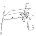
- FIG. 1 In the vehicle roof 1 shown in FIG. 1 is an adjustable hardtop with a front roof part 2 and a rear roof part 3, each of which is rigid in itself and are held by a roof kinematic 4 to the vehicle body and by means of a hydraulic cylinder. 5 trained adjusting element, which is also hinged to the vehicle body, between the closed position shown in Fig. 1 and the storage position shown in Fig. 3 is to be adjusted.
- the roof kinematics 4 comprises a four-bar link, consisting of a body-mounted drive arm 6, a likewise mounted on the body side support arm 7 and a two handlebar articulated connecting C-handlebar 8.
- the rear roof part 3 is coupled to the vehicle body, where appropriate, the C Column link 8 may also be formed by a portion of the roof part 3.
- the hydraulic cylinder 5 On the drive link 6 of the four-bar linkages the hydraulic cylinder 5, which is also pivotally mounted on the body side. If the piston rod of the hydraulic cylinder 5 is extended translationally, the drive link 6 pivots about its body-fixed axis of rotation and thereby actuates the entire roof kinematics, which leads to an actuating movement of the vehicle roof 1.
- the roof kinematics 4 further comprises a body side pivotally mounted auxiliary link 9, to which a main link 10 is pivotally coupled, the rear of the auxiliary link 9 end facing pivotally connected to the front roof part 2. Furthermore, a coupling link 16 is provided, which couples the drive link 6 with the auxiliary link 9 and is rotatably mounted both on the side of the drive link 6 and on the side of the auxiliary link 9. About this coupling a kinematic clearly defined movement of the front roof part 2 is achieved.
- the spring element 11 is designed in the embodiment as a gas spring, which is pivotally mounted on the vehicle body and engages the support arm 7 at a joint 7b.
- the support arm 7 is designed as a wishbone, which is pivotally mounted on the vehicle body via a middle joint 7a and pivotally connected to the C-pillar guide 8 via a further joint 7c, which is opposite to the joint 7b.
- the spring element 11 is arranged and designed in such a way that acts in the closed position of the vehicle roof shown in Fig.
- the torque in the direction of arrow 13 supports the movement of the roof kinematics 4 in an export movement of the hydraulic cylinder 5 in the direction of arrow 14 at the beginning of the adjusting movement, with which the vehicle roof is lifted from the closed position shown and pivoted to the storage position.
- the assisting torque generated by the spring member 11 facilitates the lifting movement out of the closed position.
- the arrow direction 13, which represents the effect of the torque on the support arm 7, is identical to the initial rotational movement of the support arm upon actuation of the hydraulic cylinder 5 for lifting the roof.
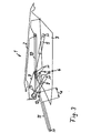
- the vehicle roof 1 is shown in an intermediate position between the closed position and the storage position.
- the hydraulic cylinder 5 is not yet fully extended and continues to move in the direction of arrow 14, so that the final storage position can be achieved.
- the support arm 7, however, has reached a reversal position: If this reversal position is exceeded, the direction of rotation of the support arm 7 is reversed from the direction of arrow 13 shown in Fig. 1 counterclockwise to the body-mounted hinge 7a in a movement in the direction of arrow 15 in a clockwise direction, so that when approaching the end position to be reached the support arm is pivoted again in the direction of its starting position.
- the spring element 11 has reached its longest elongated position, which is marked with the excavation l z , said excavation is greater than the marked with l s in Fig. 1 excavation of the spring element 11 in the closed position of vehicle roof.
- the spring element 11 expediently exerts no or a lowest possible spring force on the support arm.
- the vehicle roof 1 is shown in its storage position in a rear-side convertible top compartment.
- the rear roof part 3 is rotated relative to the closed position by approximately 180 °, in particular by about 160 °, and is located with its top down.
- the front roof part 2 has retained its original orientation and lies with the outside up directly on the rear roof part.
- the hydraulic cylinder 5 is maximally extended.
- the support arm 7 has been pivoted so far back relative to the intermediate position shown in FIG. 2, that the excavation l A of the spring element 11 is less than the excavation l Z , which corresponds to the intermediate position of FIG.
- the spring element 11 exerts in the storage position a spring force in the direction of arrow 12 on the support arm 7, whereby it experiences a counterclockwise acting torque acting in the closing direction of the vehicle roof, whereby the lifting operation the storage position is supported out to close the roof by the spring element 11.
- FIGS. 4a and 5a show the vehicle roof in the closed position
- Figs. 4b and 5b represent a transition position between the closing and storage position
- Figs. 4c and 5c show the vehicle roof in the stored position.
- a supported on the vehicle body spring element 11 which engages a side arm 10a of the main link 10 and exerts a spring force F at the point of attack on the side arm 10a.
- the side arm 10a is formed integrally with the main link 10 and encloses an angle with respect to the main link 10.
- the spring element 11 acts on the main link 10 in the closed position of the vehicle roof 1 with a torque acting around the pivot 17 in the direction of the opposite storage position and in the storage position of the vehicle roof in the direction of the opposite closed position.
- the line of action of the spring element 11 intersects the pivot joint of the main link 10, so that the lever arm is zero and no effective torque is transmitted to the main link 10 about the rotational axis of the swivel joint.
- the spring element can also be in an at least approximately relaxed position, so that in this position no spring force is exerted on the side arm 10a and no torque on the main link 10.
- the spring element 11 is designed as a tension spring, which is articulated at one end to the vehicle body and the other end to the side arm 10a and in its tensioned position - as shown in FIGS. 4a and 4c - on the side arm 10a exerts a tensile force according to the arrow F drawn.
- the spring element 11 is designed as a compression spring, which is articulated in an analogous manner to the previous embodiment at one end to the vehicle body and the other end on the side arm 10, but in the end positions of FIG. 5a and 5c on the Side arm 10a exerts a compressive force according to arrows drawn.
- both as a tension spring and as a compression spring - the lifting of the vehicle roof from each end position is supported.
- an embodiment of the spring element 11 comes as a torsion spring into consideration, which generates a torque acting on the pivot 17 on the main link 11.
- the torsion spring is designed in particular in such a way or integrated into the kinematics that in an intermediate position between the end positions no torque is generated or transmitted to the main link.
- the load of the roof kinematics distributed to two different components of the roof kinematics, namely on the acted upon by the passive spring element main link and acted upon by the active drive C-pillar.
- the passively acting spring element supports the rotational movement generated by the active drive, so that small-sized drives can be used. This opens the possibility to use standardized drive units for different roof systems or vehicle roofs and to make individual adjustments on the selection of different strength springs in the passive spring elements.
- Another advantage is the use of active and / or passive rotary actuators, wherein the passive rotary actuators and the translationally linear, acting directly on a leg or side arm of the main link spring elements are to be counted.
- rotary actuators can be dispensed with the use of gearboxes to implement the translatory actuating movement in a rotary rotary motion.
Landscapes
- Engineering & Computer Science (AREA)
- Mechanical Engineering (AREA)
- Body Structure For Vehicles (AREA)
- Lock And Its Accessories (AREA)
- Fittings On The Vehicle Exterior For Carrying Loads, And Devices For Holding Or Mounting Articles (AREA)
Claims (6)
- Toit de véhicule mobile, comprenant une cinématique de toit (4), par le biais de laquelle le toit du véhicule (1) doit être déplacé au moyen d'un élément de commande (5) maintenu fixement sur la carrosserie, qui vient en prise avec la cinématique de toit (4), entre deux positions d'extrémité - une position de fermeture et une position de rangement -, un élément de ressort (11) étant supporté sur la carrosserie du véhicule, lequel sollicite par une force la cinématique de toit (4) dans chaque position d'extrémité du toit du véhicule (1) dans la direction de la position d'extrémité opposée,
caractérisé en ce que le toit du véhicule présente une partie de toit avant (2) et une partie de toit arrière (3) et en ce que
la cinématique de toit (4) comprend un quadrilatère articulé avec deux bras oscillants (6, 7) supportés du côté de la carrosserie et un bras oscillant du montant de custode (8) situé entre les deux, un des bras oscillants du côté de la carrosserie étant sollicité en tant que bras oscillant d'entraînement (6) par l'élément de commande (5) et le deuxième bras oscillant du côté de la carrosserie étant sollicité en tant que bras oscillant de support (7) par l'élément de ressort (11), et en ce que la cinématique de toit (4) présente un bras oscillant auxiliaire (9) monté pivotant du côté de la carrosserie, auquel est accouplé de manière pivotante un bras oscillant principal (10) accouplé de manière pivotante à la partie de toit avant (2), et en ce qu'un bras oscillant d'accouplement (16) est prévu, lequel accouple le bras oscillant d'entraînement (6) au bras oscillant auxiliaire (9) et est monté de manière rotative à la fois du côté du bras oscillant d'entraînement (6) et du côté du bras oscillant auxiliaire (9). - Toit de véhicule selon la revendication 1,
caractérisé en ce que
le bras oscillant de support (7) est réalisé sous forme de bras oscillant triangulaire, qui est maintenu fixement à la carrosserie par le biais de son articulation centrale (7a), la connexion au bras oscillant de la colonne de custode (8) ou à l'élément de ressort (11) étant créée par le biais des deux articulations extérieures (7b, 7c) du bras oscillant de support (7). - Toit de véhicule selon la revendication 1 ou 2,
caractérisé en ce que l'élément de ressort (11) venant en prise avec la cinématique de toit (4) est sollicité par ressort dans les deux positions d'extrémité du toit du véhicule dans le même sens d'action. - Toit de véhicule selon l'une quelconque des revendications 1 à 3,
caractérisé en ce que
la force de ressort transmise de l'élément de ressort (11) à la cinématique de toit (4) pratiquement nulle dans une position intermédiaire du toit (1) entre les deux positions d'extrémité. - Toit de véhicule selon l'une quelconque des revendications 1 à 4,
caractérisé en ce que
l'élément de ressort (11) est un ressort pneumatique à gaz. - Toit de véhicule selon l'une quelconque des revendications 1 à 5,
caractérisé en ce que
le toit du véhicule (1) est réalisé sous forme de hard-top avec au moins deux parties de toit rigides (2, 3).
Applications Claiming Priority (5)
| Application Number | Priority Date | Filing Date | Title |
|---|---|---|---|
| DE10158938 | 2001-12-03 | ||
| DE2001158938 DE10158938A1 (de) | 2001-12-03 | 2001-12-03 | Verstellbares Fahrzeugdach |
| DE10206650 | 2002-02-15 | ||
| DE10206650A DE10206650A1 (de) | 2001-12-03 | 2002-02-15 | Verstellbares Fahrzeugdach |
| PCT/EP2002/012370 WO2003047896A1 (fr) | 2001-12-03 | 2002-11-06 | Toit de vehicule mobile |
Publications (3)
| Publication Number | Publication Date |
|---|---|
| EP1361966A1 EP1361966A1 (fr) | 2003-11-19 |
| EP1361966B1 EP1361966B1 (fr) | 2004-09-22 |
| EP1361966B2 true EP1361966B2 (fr) | 2007-06-13 |
Family
ID=26010694
Family Applications (1)
| Application Number | Title | Priority Date | Filing Date |
|---|---|---|---|
| EP02804173A Expired - Lifetime EP1361966B2 (fr) | 2001-12-03 | 2002-11-06 | Toit de vehicule mobile |
Country Status (4)
| Country | Link |
|---|---|
| US (1) | US6811205B2 (fr) |
| EP (1) | EP1361966B2 (fr) |
| DE (2) | DE10206650A1 (fr) |
| WO (1) | WO2003047896A1 (fr) |
Cited By (1)
| Publication number | Priority date | Publication date | Assignee | Title |
|---|---|---|---|---|
| DE102006057509A1 (de) * | 2006-12-06 | 2008-06-12 | Volkswagen Ag | Aufstelldach für ein Fahrzeug, insbesondere für ein Campingfahrzeug |
Families Citing this family (12)
| Publication number | Priority date | Publication date | Assignee | Title |
|---|---|---|---|---|
| DE102004019244B4 (de) * | 2004-04-16 | 2006-06-01 | Cts Fahrzeug-Dachsysteme Gmbh | Lenkerkinematik für ein Fahrzeug-Hardtop |
| DE102004035093B4 (de) * | 2004-07-20 | 2012-06-14 | Webasto-Edscha Cabrio GmbH | Verdeck für ein Cabriolet-Fahrzeug |
| FR2891203B1 (fr) * | 2005-09-29 | 2007-11-16 | Heuliez Sa | Vehicule equipe d'un toit escamotable a actionnement manuel |
| DE102006002030B3 (de) * | 2006-01-13 | 2007-07-12 | Edscha Cabrio-Dachsysteme Gmbh | Heckscheibenansteuerung |
| DE102006020759B3 (de) * | 2006-05-03 | 2007-09-13 | Magna Car Top Systems Gmbh | Bewegliches Dachteil in einem Fahrzeugdach |
| DE102006062717A1 (de) * | 2006-05-03 | 2007-11-15 | Magna Car Top Systems Gmbh | Bewegliches Dachteil in einem Fahrzeugdach |
| DE102006042202B4 (de) * | 2006-09-08 | 2024-08-08 | Dr. Ing. H.C. F. Porsche Aktiengesellschaft | Verdeckantrieb |
| DE102006042287A1 (de) * | 2006-09-08 | 2008-03-27 | Dr.Ing.H.C. F. Porsche Ag | Verstellbares Dach |
| DE102007018017B3 (de) | 2007-04-17 | 2008-11-20 | Magna Car Top Systems Gmbh | Umwandelbares Dach für einen Personenkraftwagen |
| DE102008019058A1 (de) * | 2008-04-15 | 2009-10-29 | Magna Car Top Systems Gmbh | Bewegliches Dachteil in einem Fahrzeugdach |
| DE102008026597B4 (de) | 2008-06-03 | 2015-08-27 | Rausch & Pausch Gmbh | Cabrioverdeckvorrichtung |
| DE102009009594B4 (de) * | 2009-02-19 | 2012-10-18 | Webasto-Edscha Cabrio GmbH | Verdeck für ein Cabriolet-Fahrzeug |
Family Cites Families (11)
| Publication number | Priority date | Publication date | Assignee | Title |
|---|---|---|---|---|
| BE493260A (fr) * | ||||
| DE869159C (de) * | 1941-06-25 | 1953-04-02 | Auto Union A G | Klappverdeck fuer Kraftfahrzeuge |
| DE3236034C2 (de) * | 1982-09-29 | 1985-11-21 | Ernst Dipl.-Ing. 7801 Schallstadt Maier | Schwenkbares Fahrzeugdach |
| DE3901051A1 (de) * | 1988-03-31 | 1989-10-19 | Daimler Benz Ag | Schwenkunterstuetzung eines den unteren abschluss eines klappverdecks bildenden dachhauthaltebuegels |
| DE4026392C2 (de) | 1990-08-21 | 1999-06-02 | Westfalia Werke Knoebel | Knickstütze für die Aufstelldächer von Fahrzeugen oder dergleichen |
| DE4311260C1 (de) * | 1993-04-06 | 1994-06-01 | Daimler Benz Ag | Federanordnung zur Hilfskraftunterstützung einer schwenkbeweglichen Fahrzeugabdeckung |
| DE4445580C1 (de) * | 1994-12-20 | 1995-12-21 | Daimler Benz Ag | Hardtop-Fahrzeug |
| DE19805477C1 (de) * | 1998-02-11 | 1999-08-05 | Daimler Chrysler Ag | Hardtop-Fahrzeug |
| DE19960010C2 (de) | 1999-12-13 | 2003-07-31 | Cts Fahrzeug Dachsysteme Gmbh | Klappverdeck für Fahrzeuge, insbesondere Personenkraftwagen |
| DE10021333C1 (de) * | 2000-05-02 | 2001-08-09 | Karmann Gmbh W | Cabriolet-Fahrzeug |
| DE10021340C1 (de) * | 2000-05-02 | 2001-08-09 | Karmann Gmbh W | Cabriolet-Fahrzeug |
-
2002
- 2002-02-15 DE DE10206650A patent/DE10206650A1/de not_active Withdrawn
- 2002-11-06 EP EP02804173A patent/EP1361966B2/fr not_active Expired - Lifetime
- 2002-11-06 DE DE50201103T patent/DE50201103D1/de not_active Expired - Lifetime
- 2002-11-06 WO PCT/EP2002/012370 patent/WO2003047896A1/fr not_active Ceased
-
2003
- 2003-11-08 US US10/704,493 patent/US6811205B2/en not_active Expired - Fee Related
Cited By (2)
| Publication number | Priority date | Publication date | Assignee | Title |
|---|---|---|---|---|
| DE102006057509A1 (de) * | 2006-12-06 | 2008-06-12 | Volkswagen Ag | Aufstelldach für ein Fahrzeug, insbesondere für ein Campingfahrzeug |
| DE102006057509B4 (de) * | 2006-12-06 | 2019-01-03 | Volkswagen Ag | Aufstelldach für ein Fahrzeug, insbesondere für ein Campingfahrzeug |
Also Published As
| Publication number | Publication date |
|---|---|
| DE10206650A1 (de) | 2003-09-04 |
| EP1361966A1 (fr) | 2003-11-19 |
| DE50201103D1 (de) | 2004-10-28 |
| US20040094987A1 (en) | 2004-05-20 |
| WO2003047896A1 (fr) | 2003-06-12 |
| EP1361966B1 (fr) | 2004-09-22 |
| US6811205B2 (en) | 2004-11-02 |
Similar Documents
| Publication | Publication Date | Title |
|---|---|---|
| DE10108493B4 (de) | Antriebsvorrichtung für ein Klappverdeck und Klappverdeck für ein Cabriolet-Fahrzeug mit einer solchen Antriebsvorrichtung | |
| EP1361966B2 (fr) | Toit de vehicule mobile | |
| EP1852290B1 (fr) | Partie de toit mobile dans un toit de véhicule | |
| EP1852291B1 (fr) | Partie de toit mobile dans un toit de véhicule | |
| EP1658188B1 (fr) | Couvercle de coffre pour un vehicule cabriolet | |
| EP1314601B1 (fr) | Toit ouvrant de véhicule avec une capote pliante | |
| DE102005005237B3 (de) | Anordnung zum Schwenken der Teile eines Fahrzeugverdecks | |
| DE19912893C2 (de) | Cabrio-Fahrzeug mit einem Verdeck | |
| DE10117769B4 (de) | Vorrichtung zur Unterstützung einer Öffnungsbewegung einer Fahrzeugklappe | |
| DE10158938A1 (de) | Verstellbares Fahrzeugdach | |
| DE10116094C2 (de) | Bewegliches Dachteil in einem Fahrzeugdach | |
| EP1853448B1 (fr) | Dispositif de commande d'un composant pivotant d'un vehicule | |
| DE10163727A1 (de) | Hardtop-Fahrzeugdach | |
| DE10337353A1 (de) | Cabriolet-Fahrzeug | |
| EP2110278B1 (fr) | Composant de toit mobile dans un toit de véhicule | |
| EP2125411A2 (fr) | Toit de véhicule escamotable comportant un système à quatre joints articulés | |
| EP1673250B1 (fr) | Toit escamotable destine a un vehicule | |
| EP1798090B1 (fr) | Plage arrière pour cabriolet | |
| DE102008036907B4 (de) | Faltverdeck für einen Personenkraftwagen | |
| DE102006058320B4 (de) | Cabriolet-Fahrzeug mit angetriebenem Hauptlenkersystem | |
| DE102009036585B4 (de) | Faltverdeck mit einer Federkrafteinrichtung zur Gewichtsentlastung | |
| EP1848603A1 (fr) | Toit rigide | |
| DE10149228A1 (de) | Verstellbares Fahrzeugdach | |
| DE10243070A1 (de) | Klappverdeck für Fahrzeuge | |
| DE102011119432A1 (de) | Verstellbares Fahrzeugdach für ein Cabriolet-Fahrzeug |
Legal Events
| Date | Code | Title | Description |
|---|---|---|---|
| PUAI | Public reference made under article 153(3) epc to a published international application that has entered the european phase |
Free format text: ORIGINAL CODE: 0009012 |
|
| 17P | Request for examination filed |
Effective date: 20030922 |
|
| AK | Designated contracting states |
Kind code of ref document: A1 Designated state(s): AT BE BG CH CY CZ DE DK EE ES FI FR GB GR IE IT LI LU MC NL PT SE SK TR |
|
| 17Q | First examination report despatched |
Effective date: 20031028 |
|
| GRAP | Despatch of communication of intention to grant a patent |
Free format text: ORIGINAL CODE: EPIDOSNIGR1 |
|
| GRAS | Grant fee paid |
Free format text: ORIGINAL CODE: EPIDOSNIGR3 |
|
| GRAA | (expected) grant |
Free format text: ORIGINAL CODE: 0009210 |
|
| AK | Designated contracting states |
Kind code of ref document: B1 Designated state(s): DE FR GB |
|
| PG25 | Lapsed in a contracting state [announced via postgrant information from national office to epo] |
Ref country code: FR Free format text: LAPSE BECAUSE OF FAILURE TO SUBMIT A TRANSLATION OF THE DESCRIPTION OR TO PAY THE FEE WITHIN THE PRESCRIBED TIME-LIMIT Effective date: 20040922 Ref country code: GB Free format text: LAPSE BECAUSE OF FAILURE TO SUBMIT A TRANSLATION OF THE DESCRIPTION OR TO PAY THE FEE WITHIN THE PRESCRIBED TIME-LIMIT Effective date: 20040922 |
|
| RBV | Designated contracting states (corrected) |
Designated state(s): DE FR GB |
|
| REG | Reference to a national code |
Ref country code: GB Ref legal event code: FG4D Free format text: NOT ENGLISH |
|
| RIN1 | Information on inventor provided before grant (corrected) |
Inventor name: ROESLER, MATTHIAS Inventor name: BRUDER, GERNOT Inventor name: HASSELGRUBER, ANDREAS Inventor name: BERTZ, FRANK Inventor name: PAPENDORF, MARCUS Inventor name: SALZ, WOLFRAM |
|
| REG | Reference to a national code |
Ref country code: IE Ref legal event code: FG4D Free format text: GERMAN |
|
| REF | Corresponds to: |
Ref document number: 50201103 Country of ref document: DE Date of ref document: 20041028 Kind code of ref document: P |
|
| GBV | Gb: ep patent (uk) treated as always having been void in accordance with gb section 77(7)/1977 [no translation filed] |
Effective date: 20040922 |
|
| REG | Reference to a national code |
Ref country code: IE Ref legal event code: FD4D |
|
| PLAQ | Examination of admissibility of opposition: information related to despatch of communication + time limit deleted |
Free format text: ORIGINAL CODE: EPIDOSDOPE2 |
|
| PLBQ | Unpublished change to opponent data |
Free format text: ORIGINAL CODE: EPIDOS OPPO |
|
| PLAQ | Examination of admissibility of opposition: information related to despatch of communication + time limit deleted |
Free format text: ORIGINAL CODE: EPIDOSDOPE2 |
|
| PLAR | Examination of admissibility of opposition: information related to receipt of reply deleted |
Free format text: ORIGINAL CODE: EPIDOSDOPE4 |
|
| PLBI | Opposition filed |
Free format text: ORIGINAL CODE: 0009260 |
|
| PLBQ | Unpublished change to opponent data |
Free format text: ORIGINAL CODE: EPIDOS OPPO |
|
| RAP2 | Party data changed (patent owner data changed or rights of a patent transferred) |
Owner name: CTS FAHRZEUG-DACHSYSTEME GMBH |
|
| PLAX | Notice of opposition and request to file observation + time limit sent |
Free format text: ORIGINAL CODE: EPIDOSNOBS2 |
|
| 26 | Opposition filed |
Opponent name: OPEN AIR SYSTEMS GMBH Effective date: 20050622 |
|
| PLBB | Reply of patent proprietor to notice(s) of opposition received |
Free format text: ORIGINAL CODE: EPIDOSNOBS3 |
|
| EN | Fr: translation not filed | ||
| PLAY | Examination report in opposition despatched + time limit |
Free format text: ORIGINAL CODE: EPIDOSNORE2 |
|
| PLAT | Information related to reply to examination report in opposition deleted |
Free format text: ORIGINAL CODE: EPIDOSDORE3 |
|
| PLBC | Reply to examination report in opposition received |
Free format text: ORIGINAL CODE: EPIDOSNORE3 |
|
| PLBC | Reply to examination report in opposition received |
Free format text: ORIGINAL CODE: EPIDOSNORE3 |
|
| PUAH | Patent maintained in amended form |
Free format text: ORIGINAL CODE: 0009272 |
|
| STAA | Information on the status of an ep patent application or granted ep patent |
Free format text: STATUS: PATENT MAINTAINED AS AMENDED |
|
| 27A | Patent maintained in amended form |
Effective date: 20070613 |
|
| AK | Designated contracting states |
Kind code of ref document: B2 Designated state(s): DE FR GB |
|
| EN | Fr: translation not filed | ||
| PGFP | Annual fee paid to national office [announced via postgrant information from national office to epo] |
Ref country code: DE Payment date: 20131121 Year of fee payment: 12 |
|
| REG | Reference to a national code |
Ref country code: DE Ref legal event code: R119 Ref document number: 50201103 Country of ref document: DE |
|
| PG25 | Lapsed in a contracting state [announced via postgrant information from national office to epo] |
Ref country code: DE Free format text: LAPSE BECAUSE OF NON-PAYMENT OF DUE FEES Effective date: 20150602 |