EP1361992B1 - Lade- und entladefläche - Google Patents
Lade- und entladefläche Download PDFInfo
- Publication number
- EP1361992B1 EP1361992B1 EP02712523A EP02712523A EP1361992B1 EP 1361992 B1 EP1361992 B1 EP 1361992B1 EP 02712523 A EP02712523 A EP 02712523A EP 02712523 A EP02712523 A EP 02712523A EP 1361992 B1 EP1361992 B1 EP 1361992B1
- Authority
- EP
- European Patent Office
- Prior art keywords
- floor
- parts
- loading
- unloading
- group
- Prior art date
- Legal status (The legal status is an assumption and is not a legal conclusion. Google has not performed a legal analysis and makes no representation as to the accuracy of the status listed.)
- Expired - Lifetime
Links
- 230000008878 coupling Effects 0.000 description 20
- 238000010168 coupling process Methods 0.000 description 20
- 238000005859 coupling reaction Methods 0.000 description 20
- 239000013590 bulk material Substances 0.000 description 13
- 238000006073 displacement reaction Methods 0.000 description 8
- 230000000694 effects Effects 0.000 description 2
- 230000002411 adverse Effects 0.000 description 1
- XAGFODPZIPBFFR-UHFFFAOYSA-N aluminium Chemical compound [Al] XAGFODPZIPBFFR-UHFFFAOYSA-N 0.000 description 1
- 229910052782 aluminium Inorganic materials 0.000 description 1
- 239000004411 aluminium Substances 0.000 description 1
- 239000002361 compost Substances 0.000 description 1
- 239000003337 fertilizer Substances 0.000 description 1
- 238000004382 potting Methods 0.000 description 1
Images


Classifications
-
- B—PERFORMING OPERATIONS; TRANSPORTING
- B65—CONVEYING; PACKING; STORING; HANDLING THIN OR FILAMENTARY MATERIAL
- B65G—TRANSPORT OR STORAGE DEVICES, e.g. CONVEYORS FOR LOADING OR TIPPING, SHOP CONVEYOR SYSTEMS OR PNEUMATIC TUBE CONVEYORS
- B65G25/00—Conveyors comprising a cyclically-moving, e.g. reciprocating, carrier or impeller which is disengaged from the load during the return part of its movement
- B65G25/04—Conveyors comprising a cyclically-moving, e.g. reciprocating, carrier or impeller which is disengaged from the load during the return part of its movement the carrier or impeller having identical forward and return paths of movement, e.g. reciprocating conveyors
- B65G25/06—Conveyors comprising a cyclically-moving, e.g. reciprocating, carrier or impeller which is disengaged from the load during the return part of its movement the carrier or impeller having identical forward and return paths of movement, e.g. reciprocating conveyors having carriers, e.g. belts
- B65G25/065—Reciprocating floor conveyors
Definitions
- the invention relates to a loading and unloading floor for a loading space, provided with one or more parallel and adjacent groups of floor parts, each group comprising elongate floor parts which extend adjacent to one another, each group comprising at least a first and a second floor part which can be slideably displaced in a reciprocating manner in the longitudinal direction and a stationary floor part, which first and second floor parts can be driven by actuator means (e.g. see: document US-A-4 798 802).
- Another loading and unloading floor of this type is known from US-A 4,962,848.
- all the groups have a first and a second displaceable floor part and a stationary floor part. Furthermore, all the floor parts are of the same width.
- An object which is placed on the floor is carried along when, for each group, the two displaceable floor parts are displaced. If only one of the two displaceable floor parts of each group is displaced, the object is not carried along and is therefore not moved.
- the known floor operates well when, for example, boxes or crates are being conveyed. In practice, however, this application is less important. A more significant and more frequent application is that of conveying loose bulk material, such as for example grain, domestic refuse, potting compost or fertilizer.
- the known loading and unloading floor does not cope well with loading and unloading loose bulk material.
- the object of the invention is to provide an improved loading and unloading floor which operates well even when loading and unloading loose bulk material.
- This object is achieved by a loading and unloading floor of the type described above, characterized in that the stationary floor parts make up less than 33% of the floor area.
- An expedient embodiment of the loading and unloading floor according to the invention is characterized in that the stationary floor parts make up at most 27% of the floor area. This is achieved, for example, by selecting the width of the stationary floor parts and the number of stationary floor parts to be such that, during the simultaneous movement of the first and second floor parts, at least 73% of the floor area moves. This provides an additional conveying capacity, so that loose bulk material can virtually always overcome the residual friction.
- a preferred embodiment of the loading and unloading floor according to the invention is characterized in that in at least one group the stationary floor part has a narrower width than that of the first and second floor parts.
- the stationary floor parts being designed with narrower width than the first and second floor parts, it is possible to reduce the stationary surface area compared to that of the known loading and unloading floor.
- This reduction which means that, during displacement of the first and second floor parts, a smaller area of the floor resists the movement of the bulk material in the direction of displacement of the first and second floor parts, can also be achieved with a loading and unloading floor in which the loading and unloading floor, in addition to the groups of floor parts with a stationary floor part, also comprises groups of floor parts which have only displaceable floor parts.
- the first floor parts and the second floor parts are of the same width.
- the width of the stationary floor parts and the number of stationary floor parts are such that, during the individual movement of the first or second floor parts, at most 45% of the floor area is moving. This ensures that the floor is suitable for different types of load and that, for example, boxes and crates remain stationary when the first or second floor parts are being displaced.
- a further highly expedient embodiment of the invention is characterized in that the groups of floor parts are secured releasably, so that they can be fitted when it is necessary for an awkward load to be conveyed.
- the loading space with side walls, the side walls being provided with one or more groups of wall parts, which lie parallel to and above one another, each group comprising elongate wall parts which extend above one another, each group comprising at least a first and a second wall part which can be displaced in a reciprocating manner in the longitudinal direction, and a stationary wall part, it being possible for the displaceable wall parts of each group to be displaced simultaneously.
- An advantageous embodiment of the loading space with displaceable first and second wall parts and stationary wall parts in which all the wall parts can be designed with an identical width is characterized in that at least 10% of the area of the side walls is provided with groups of wall parts. These additional wall parts reduce the friction caused by the side walls to such an extent that loose bulk material can be conveyed even more successfully.
- a further advantageous embodiment of the loading space which makes use of the fact that the pressure is greatest at a bottom part of the side walls is characterized in that, of the two side walls, a region which adjoins the floor is provided with groups of wall parts.
- An additional advantage is that groups of wall parts positioned in this way can easily be coupled to the floor parts positioned in the loading and unloading floor.
- the invention also relates to a vehicle, such as a lorry or a trailer, provided with a loading and unloading floor as described above, and to a vehicle provided with a loading space as described above.
- the invention also relates to a container or hopper provided with a loading and unloading floor as described above.
- Fig. 1 diagrammatically depicts a loading and unloading floor according to the prior art, comprising groups of in each case three floor parts 1, 2, 3 in slat form.
- the floor parts comprise U-shaped profiled sections made, for example, from aluminium, the closed part of the U-shaped profiled sections facing upwards, with plastic guides 4 positioned between the limbs, which guides in turn rest on a bar 5 which forms part of the chassis of the loading space, generally a loading space of a lorry or trailer.
- Floor parts 1 are connected, via a coupling member 6 to a hydraulic cylinder 7 and floor parts 2 are connected, via a coupling member 8 to a hydraulic cylinder 9, while floor parts 3 are stationary.
- the illustration in the figure is diagrammatic, but a detailed embodiment is known from the above-cited patent US-A 4,962,848.
- the loading and unloading floor When an object has been placed on the loading and unloading floor, it can be displaced by, for example, firstly moving the floor parts 1 to the left in the figure, then moving the floor parts 2 to the left, and then moving both groups of floor parts to the right, during which movement the object also moves to the right.
- the reason for this is that when floor parts 1 or floor parts 2 are moving to the left, only 33% of the floor area is moving and the object will remain stationary, while when floor parts 1 and floor parts 2 together are moving to the right, 66.6% of the floor area is moving to the right and the object will be carried along with them.
- the known floor operates well, if, for example, boxes or crates are being conveyed. However, the known loading and unloading floor has not proven to operate satisfactorily for loading and unloading loose bulk material.
- Fig. 2 diagrammatically depicts a loading and unloading floor according to the invention, in which the floor parts 3 are much narrower than floor parts 1 and floor parts 2.
- the width of a floor part 3 is only 40% of the width of floor part 1 and floor part 2. This means that when floor parts 1 and floor parts 2 are moving together some 83% of the floor is moving, a situation in which even loose bulk material will also be carried along with the floor parts.
- floor parts 3 must have a minimum width, in such a manner that at most 45% of the floor moves. For loose bulk material, the situation is different. In this case, the resistance of the side walls can be used to good effect, and the floor parts 3 may be even narrower than for conveying objects.
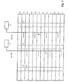
- Fig. 3 diagrammatically depicts one possible embodiment of a loading and unloading floor having, at the sides, groups comprising only first and second floor parts 1, 2, which are connected to actuators 7, 9 via coupling members 6, 8.
- the groups which lie in the centre have first and second displaceable floor parts 1, 2 and stationary floor parts 3.
- the stationary floor parts 3 of each group are positioned between the first and second floor parts 1, 2 of the same group.
- the stationary floor parts 3 are much narrower than the first and second floor parts 1, 2 and, in the embodiment shown, cover approximately 10% of the floor area.
- the stationary floor parts may also cover a larger percentage of the floor area, preferably approximately 17%, which in practice has been found to provide optimum operation of the floor.
- Fig. 2 shows that the coupling member 6 is provided with two vertically positioned sleeves 10, 11 and that the coupling member 8 is provided with two vertically positioned sleeves 12, 13, on which active side walls may be arranged.
- the coupling member 6 is provided with two vertically positioned sleeves 10, 11 and that the coupling member 8 is provided with two vertically positioned sleeves 12, 13, on which active side walls may be arranged.
- these coupling members slide into the sleeves 10, 11, 12, 13 and these coupling members will also be moved up and down with the aid of hydraulic cylinders 7, 9.
- Fig. 4 diagrammatically depicts one possible embodiment of an active side wall provided with wall parts 21, 22, 23 and with two coupling members 14, 15 which are provided with interface plates 16, 17 which, during positioning of the side wall, for example fit into the sleeves 11, 13.
- the active side wall is virtually identical to the loading and unloading floor and is provided with transverse bars 5, on which plastic guides 4 are positioned, over which the wall parts, which are U-shaped in cross section, can slide.
- the active side wall it is generally possible for the active side wall to be of somewhat lighter design, since the mechanical load is lower.
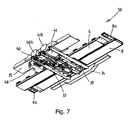
- Figs. 6 and 7 show a drive unit 50 which is used to drive the displaceable floor parts 1, 2 of the loading and unloading floor according to the invention.
- the drive unit 50 comprises a first coupling member 6 and a coupling member 8.
- the coupling member 6 comprises an elongate bar 6b which is positioned transversely with respect to the direction of displacement of the floor parts 1, 2 and is provided with securing profiled sections 6a which are positioned transversely thereon and can be secured to the first floor parts 1.
- the coupling member 8 comprises an elongate bar 8b which is positioned transversely to the direction of displacement of the floor parts 1, 2 and is provided with securing profiled sections 8a which are positioned transversely thereon and can be secured to the first floor parts 2.
- the coupling member 6 can be moved in a reciprocating manner over guide profiled sections 32 and 33.
- the coupling member 8 can be moved in a reciprocating manner over guide profiled sections 30 and 31.
- These guide profiled sections 30-33 extend between transverse profiled sections 34 and 35, by means of which the drive unit 50 can be secured to the chassis of the loading space.
- Two drive cylinders 40, 41 are arranged beneath the transverse profiled section 35 as actuator means, these cylinders being used to drive the coupling members 6 and 8, respectively.
- the ends 40a, 40b of one drive cylinder 40 can be seen.
- the ends 41a, 41b of the other drive cylinder 41 can be seen.
- a piston rod 45 extends from the end 40a of the drive cylinder 40, which piston rod engages on the underside of the coupling member 6.
- a piston rod 46 extends from the end 41a of the drive cylinder 41, which piston rod engages on the underside of the coupling member 8. It can be seen from Fig. 7 that the drive cylinders 40, 41 are connected via lines to a valve block 48, which valve block 48 is connected to a hydraulic circuit (not shown).
- the embodiments described here always use one hydraulic cylinder and a coupling member to actuate the floor parts associated with the said cylinder. It is also possible to fit one small hydraulic cylinder for each floor part. The coupling member can then be omitted.
Landscapes
- Engineering & Computer Science (AREA)
- Mechanical Engineering (AREA)
- Reciprocating Conveyors (AREA)
- Loading Or Unloading Of Vehicles (AREA)
- Forklifts And Lifting Vehicles (AREA)
Claims (14)
- Be- und Entladeboden für einen Laderaum, ausgebildet mit einer oder mehreren parallelen und benachbarten Gruppen an Bodenteilen (1-3), wobei jede Gruppe längliche Bodenteile (1-3) umfasst, die sich benachbart zu einander erstrecken, wobei jede Gruppe zumindest ein erstes und ein zweites Bodenteil (1, 2) umfasst, das gleitbar hin und her in Längsrichtung versetzt werden kann, und ein stationäres Bodenteil (3), wobei das erste und das zweite Bodenteil (1, 2) mittels eines Aktormittels (7, 9) angetrieben werden kann, dadurch gekennzeichnet, dass die stationären Bodenteile (3) 16-18% der Bodenfläche ausmachen.
- Be- und Entladeboden nach Anspruch 1, dadurch gekennzeichnet, dass in zumindest einer Gruppe das stationäre Bodenteil (3) eine schmalere Breite als das erste und zweite Bodenteil (1, 2) aufweist.
- Be- und Entladeboden gemäß Anspruch 1 oder 2, dadurch gekennzeichnet, dass der Be- und Entladeboden zusätzlich zu den Gruppen an Bodenteilen mit einem stationären Bodenteil (3) auch Gruppen mit Bodenteilen umfasst, welche nur gleitbar versetzbare Bodenteile (1, 2) aufweisen.
- Be- und Entladeboden gemäß einem der vorherigen Ansprüche, dadurch gekennzeichnet, dass die ersten Bodenteile (1) und die zweiten Bodenteile (2) die gleiche Breite aufweisen.
- Be- und Entladeboden gemäß Anspruch 4, dadurch gekennzeichnet, dass die ersten Bodenteile (1) zusammen höchstens 45% der Bodenfläche ausmachen und die zweiten Bodenteile (2) zusammen höchstens 45% der Bodenfläche ausmachen.
- Be- und Entladeboden gemäß einem der vorherigen Ansprüche, dadurch gekennzeichnet, dass die Gruppe der Bodenteile (1, 2, 3) lösbar gesichert ist.
- Be- und Entladeboden gemäß einem der vorherigen Ansprüche, dadurch gekennzeichnet, dass die ersten Bodenteile (1) jeder Gruppe gleichzeitig versetzt werden können und die zweiten Bodenteile (2) jeder Gruppe gleichzeitig versetzt werden können.
- Be- und Entladeboden gemäß Anspruch 7, dadurch gekennzeichnet, dass die ersten Bodenteile (1) jeder Gruppe miteinander gekoppelt sind und mit einem ersten Aktormittel (7) gekoppelt werden können und die zweiten Bodenteile (2) jeder Gruppe miteinander gekoppelt sind und mit einem zweiten Aktormittel (9) gekoppelt werden können.
- Laderaum, ausgebildet mit einem Be- und Entladeboden gemäß einem der vorherigen Ansprüche, dadurch gekennzeichnet, dass der Laderaum mit Seitenwänden ausgebildet ist, wobei die Seitenwände mit einer Gruppe oder mehreren Gruppen an Wandteilen (21, 22, 23) ausgebildet ist, welche parallel zueinander und übereinander liegen, wobei jede Gruppe längliche Wandteile (21, 22, 23) umfasst, welche sich übereinander erstrecken, wobei jede Gruppe zumindest ein erstes und ein zweites Wandteil, das gleitbar hin- und her in Längsrichtung versetzt werden kann, und ein stationäres Wandteil umfasst, wobei es für die versetzbaren Wandteile (21, 22, 23) jeder Gruppe möglich ist, gleichzeitig versetzt zu werden.
- Laderaum gemäß Anspruch 9, dadurch gekennzeichnet, dass zumindest 10% der Fläche der Seitenwände mit Gruppen von Wandteilen (21, 22, 23) ausgebildet ist.
- Laderaum gemäß Anspruch 10, dadurch gekennzeichnet, dass die Seitenwände in einem Bereich, der an den Be- und Entladeboden angrenzt, mit Gruppen von Wandteilen (21, 22, 23) ausgebildet sind.
- Fahrzeug, ausgebildet mit einem Be- und Entladeboden gemäß einem der Ansprüche 1 bis 8.
- Fahrzeug, ausgebildet mit einem Laderaum gemäß einem der Ansprüche 9 bis 11.
- Behälter oder Bunker, ausgebildet mit einem Be- und Entladeboden gemäß einem der Ansprüche 1 bis 8.
Applications Claiming Priority (5)
| Application Number | Priority Date | Filing Date | Title |
|---|---|---|---|
| NL1017422 | 2001-02-21 | ||
| NL1017422A NL1017422C1 (nl) | 2001-02-21 | 2001-02-21 | Automatische laad- en losvloer. |
| NL1019740A NL1019740C1 (nl) | 2001-02-21 | 2002-01-14 | Laad-en losvloer. |
| NL1019740 | 2002-01-14 | ||
| PCT/NL2002/000105 WO2002066346A1 (en) | 2001-02-21 | 2002-02-18 | Loading and unloading floor |
Publications (2)
| Publication Number | Publication Date |
|---|---|
| EP1361992A1 EP1361992A1 (de) | 2003-11-19 |
| EP1361992B1 true EP1361992B1 (de) | 2006-08-02 |
Family
ID=26643299
Family Applications (1)
| Application Number | Title | Priority Date | Filing Date |
|---|---|---|---|
| EP02712523A Expired - Lifetime EP1361992B1 (de) | 2001-02-21 | 2002-02-18 | Lade- und entladefläche |
Country Status (5)
| Country | Link |
|---|---|
| EP (1) | EP1361992B1 (de) |
| AT (1) | ATE334914T1 (de) |
| DE (1) | DE60213565T2 (de) |
| NL (1) | NL1019740C1 (de) |
| WO (1) | WO2002066346A1 (de) |
Families Citing this family (1)
| Publication number | Priority date | Publication date | Assignee | Title |
|---|---|---|---|---|
| US7658276B2 (en) | 2005-11-10 | 2010-02-09 | Rene Wegkamp | Drive beam |
Family Cites Families (3)
| Publication number | Priority date | Publication date | Assignee | Title |
|---|---|---|---|---|
| US4798802A (en) * | 1987-07-28 | 1989-01-17 | Ryan Richard M | Method for accelerating composting of organic matter and composting reactor therefor |
| US4966275A (en) * | 1989-01-27 | 1990-10-30 | Hallstrom Jr Olof A | Reciprocating conveyor with detachable power drive |
| US4962848A (en) | 1990-01-16 | 1990-10-16 | Foster Raymond K | Reciprocating floor conveyor |
-
2002
- 2002-01-14 NL NL1019740A patent/NL1019740C1/nl not_active IP Right Cessation
- 2002-02-18 EP EP02712523A patent/EP1361992B1/de not_active Expired - Lifetime
- 2002-02-18 AT AT02712523T patent/ATE334914T1/de not_active IP Right Cessation
- 2002-02-18 DE DE60213565T patent/DE60213565T2/de not_active Expired - Fee Related
- 2002-02-18 WO PCT/NL2002/000105 patent/WO2002066346A1/en not_active Ceased
Also Published As
| Publication number | Publication date |
|---|---|
| DE60213565D1 (de) | 2006-09-14 |
| EP1361992A1 (de) | 2003-11-19 |
| ATE334914T1 (de) | 2006-08-15 |
| NL1019740C1 (nl) | 2002-08-22 |
| WO2002066346A1 (en) | 2002-08-29 |
| DE60213565T2 (de) | 2007-10-18 |
Similar Documents
| Publication | Publication Date | Title |
|---|---|---|
| US6439375B1 (en) | Reciprocating floor conveyor for conveying palletized loads or the like | |
| US8061950B2 (en) | Container packer system and method | |
| US4966275A (en) | Reciprocating conveyor with detachable power drive | |
| US6146079A (en) | Dual blade packer system for refuse collection vehicle | |
| US8721255B2 (en) | Methods and apparatus for freight container loading | |
| US10954086B1 (en) | Container packer system and method | |
| CA2630861A1 (en) | Reciprocating slat conveyer | |
| US5560713A (en) | Ejector wear shoe | |
| JP2005041691A (ja) | ヘビーデューティ往復スラットコンベア | |
| EP1361992B1 (de) | Lade- und entladefläche | |
| CN102666317B (zh) | 可调整的往复式板条输送机 | |
| US20240124243A1 (en) | Slat for a reciprocating slat conveyor | |
| CN102770358B (zh) | 可调整的往复式板条输送机 | |
| JP3926092B2 (ja) | コンテナ | |
| EP1443003B1 (de) | Antriebsvorrichtung | |
| NL2027595B1 (en) | Slat for a reciprocating slat conveyor | |
| JP3107332U (ja) | 荷下ろし装置及びトラック | |
| JP2004017755A (ja) | 荷下ろし装置及びトラック | |
| CA2307411A1 (en) | Improved reciprocating slat floor conveyor | |
| WO2011035291A2 (en) | Under-mount slat conveyor | |
| JP2004017748A (ja) | 荷下ろし装置及びトラック | |
| JP2004017752A (ja) | 荷下ろし装置及びトラック | |
| JP2004017750A (ja) | 荷下ろし装置及びトラック | |
| KR20000019327U (ko) | 화물자동차의 화물 하강장치 | |
| JP2004017756A (ja) | 荷下ろし装置及びトラック |
Legal Events
| Date | Code | Title | Description |
|---|---|---|---|
| PUAI | Public reference made under article 153(3) epc to a published international application that has entered the european phase |
Free format text: ORIGINAL CODE: 0009012 |
|
| 17P | Request for examination filed |
Effective date: 20030821 |
|
| AK | Designated contracting states |
Kind code of ref document: A1 Designated state(s): AT BE CH CY DE DK ES FI FR GB GR IE IT LI LU MC NL PT SE TR |
|
| AX | Request for extension of the european patent |
Extension state: AL LT LV MK RO SI |
|
| GRAP | Despatch of communication of intention to grant a patent |
Free format text: ORIGINAL CODE: EPIDOSNIGR1 |
|
| GRAS | Grant fee paid |
Free format text: ORIGINAL CODE: EPIDOSNIGR3 |
|
| GRAA | (expected) grant |
Free format text: ORIGINAL CODE: 0009210 |
|
| AK | Designated contracting states |
Kind code of ref document: B1 Designated state(s): AT BE CH CY DE DK ES FI FR GB GR IE IT LI LU MC NL PT SE TR |
|
| PG25 | Lapsed in a contracting state [announced via postgrant information from national office to epo] |
Ref country code: IT Free format text: LAPSE BECAUSE OF FAILURE TO SUBMIT A TRANSLATION OF THE DESCRIPTION OR TO PAY THE FEE WITHIN THE PRESCRIBED TIME-LIMIT;WARNING: LAPSES OF ITALIAN PATENTS WITH EFFECTIVE DATE BEFORE 2007 MAY HAVE OCCURRED AT ANY TIME BEFORE 2007. THE CORRECT EFFECTIVE DATE MAY BE DIFFERENT FROM THE ONE RECORDED. Effective date: 20060802 Ref country code: FI Free format text: LAPSE BECAUSE OF FAILURE TO SUBMIT A TRANSLATION OF THE DESCRIPTION OR TO PAY THE FEE WITHIN THE PRESCRIBED TIME-LIMIT Effective date: 20060802 Ref country code: LI Free format text: LAPSE BECAUSE OF FAILURE TO SUBMIT A TRANSLATION OF THE DESCRIPTION OR TO PAY THE FEE WITHIN THE PRESCRIBED TIME-LIMIT Effective date: 20060802 Ref country code: AT Free format text: LAPSE BECAUSE OF FAILURE TO SUBMIT A TRANSLATION OF THE DESCRIPTION OR TO PAY THE FEE WITHIN THE PRESCRIBED TIME-LIMIT Effective date: 20060802 Ref country code: CH Free format text: LAPSE BECAUSE OF FAILURE TO SUBMIT A TRANSLATION OF THE DESCRIPTION OR TO PAY THE FEE WITHIN THE PRESCRIBED TIME-LIMIT Effective date: 20060802 |
|
| REG | Reference to a national code |
Ref country code: GB Ref legal event code: FG4D |
|
| REG | Reference to a national code |
Ref country code: CH Ref legal event code: EP |
|
| REG | Reference to a national code |
Ref country code: IE Ref legal event code: FG4D |
|
| REF | Corresponds to: |
Ref document number: 60213565 Country of ref document: DE Date of ref document: 20060914 Kind code of ref document: P |
|
| PG25 | Lapsed in a contracting state [announced via postgrant information from national office to epo] |
Ref country code: DK Free format text: LAPSE BECAUSE OF FAILURE TO SUBMIT A TRANSLATION OF THE DESCRIPTION OR TO PAY THE FEE WITHIN THE PRESCRIBED TIME-LIMIT Effective date: 20061102 Ref country code: SE Free format text: LAPSE BECAUSE OF FAILURE TO SUBMIT A TRANSLATION OF THE DESCRIPTION OR TO PAY THE FEE WITHIN THE PRESCRIBED TIME-LIMIT Effective date: 20061102 |
|
| PG25 | Lapsed in a contracting state [announced via postgrant information from national office to epo] |
Ref country code: ES Free format text: LAPSE BECAUSE OF FAILURE TO SUBMIT A TRANSLATION OF THE DESCRIPTION OR TO PAY THE FEE WITHIN THE PRESCRIBED TIME-LIMIT Effective date: 20061113 |
|
| PG25 | Lapsed in a contracting state [announced via postgrant information from national office to epo] |
Ref country code: PT Free format text: LAPSE BECAUSE OF FAILURE TO SUBMIT A TRANSLATION OF THE DESCRIPTION OR TO PAY THE FEE WITHIN THE PRESCRIBED TIME-LIMIT Effective date: 20070102 |
|
| REG | Reference to a national code |
Ref country code: CH Ref legal event code: PL |
|
| PG25 | Lapsed in a contracting state [announced via postgrant information from national office to epo] |
Ref country code: MC Free format text: LAPSE BECAUSE OF NON-PAYMENT OF DUE FEES Effective date: 20070228 |
|
| ET | Fr: translation filed | ||
| PLBE | No opposition filed within time limit |
Free format text: ORIGINAL CODE: 0009261 |
|
| STAA | Information on the status of an ep patent application or granted ep patent |
Free format text: STATUS: NO OPPOSITION FILED WITHIN TIME LIMIT |
|
| 26N | No opposition filed |
Effective date: 20070503 |
|
| PG25 | Lapsed in a contracting state [announced via postgrant information from national office to epo] |
Ref country code: IE Free format text: LAPSE BECAUSE OF NON-PAYMENT OF DUE FEES Effective date: 20070219 |
|
| PG25 | Lapsed in a contracting state [announced via postgrant information from national office to epo] |
Ref country code: GR Free format text: LAPSE BECAUSE OF FAILURE TO SUBMIT A TRANSLATION OF THE DESCRIPTION OR TO PAY THE FEE WITHIN THE PRESCRIBED TIME-LIMIT Effective date: 20061103 |
|
| PGFP | Annual fee paid to national office [announced via postgrant information from national office to epo] |
Ref country code: DE Payment date: 20090224 Year of fee payment: 8 Ref country code: NL Payment date: 20090227 Year of fee payment: 8 |
|
| PGFP | Annual fee paid to national office [announced via postgrant information from national office to epo] |
Ref country code: GB Payment date: 20090226 Year of fee payment: 8 |
|
| PGFP | Annual fee paid to national office [announced via postgrant information from national office to epo] |
Ref country code: BE Payment date: 20090226 Year of fee payment: 8 |
|
| PG25 | Lapsed in a contracting state [announced via postgrant information from national office to epo] |
Ref country code: LU Free format text: LAPSE BECAUSE OF NON-PAYMENT OF DUE FEES Effective date: 20070218 Ref country code: CY Free format text: LAPSE BECAUSE OF FAILURE TO SUBMIT A TRANSLATION OF THE DESCRIPTION OR TO PAY THE FEE WITHIN THE PRESCRIBED TIME-LIMIT Effective date: 20060802 |
|
| PG25 | Lapsed in a contracting state [announced via postgrant information from national office to epo] |
Ref country code: TR Free format text: LAPSE BECAUSE OF FAILURE TO SUBMIT A TRANSLATION OF THE DESCRIPTION OR TO PAY THE FEE WITHIN THE PRESCRIBED TIME-LIMIT Effective date: 20060802 |
|
| PGFP | Annual fee paid to national office [announced via postgrant information from national office to epo] |
Ref country code: FR Payment date: 20090226 Year of fee payment: 8 |
|
| BERE | Be: lapsed |
Owner name: *DE ROO BERT RONALD Effective date: 20100228 |
|
| REG | Reference to a national code |
Ref country code: NL Ref legal event code: V1 Effective date: 20100901 |
|
| GBPC | Gb: european patent ceased through non-payment of renewal fee |
Effective date: 20100218 |
|
| REG | Reference to a national code |
Ref country code: FR Ref legal event code: ST Effective date: 20101029 |
|
| PG25 | Lapsed in a contracting state [announced via postgrant information from national office to epo] |
Ref country code: NL Free format text: LAPSE BECAUSE OF NON-PAYMENT OF DUE FEES Effective date: 20100901 Ref country code: FR Free format text: LAPSE BECAUSE OF NON-PAYMENT OF DUE FEES Effective date: 20100301 |
|
| PG25 | Lapsed in a contracting state [announced via postgrant information from national office to epo] |
Ref country code: DE Free format text: LAPSE BECAUSE OF NON-PAYMENT OF DUE FEES Effective date: 20100901 Ref country code: BE Free format text: LAPSE BECAUSE OF NON-PAYMENT OF DUE FEES Effective date: 20100228 |
|
| PG25 | Lapsed in a contracting state [announced via postgrant information from national office to epo] |
Ref country code: GB Free format text: LAPSE BECAUSE OF NON-PAYMENT OF DUE FEES Effective date: 20100218 |