EP1362773A2 - Système de propulsion pour véhicules à chenilles - Google Patents
Système de propulsion pour véhicules à chenilles Download PDFInfo
- Publication number
- EP1362773A2 EP1362773A2 EP03010332A EP03010332A EP1362773A2 EP 1362773 A2 EP1362773 A2 EP 1362773A2 EP 03010332 A EP03010332 A EP 03010332A EP 03010332 A EP03010332 A EP 03010332A EP 1362773 A2 EP1362773 A2 EP 1362773A2
- Authority
- EP
- European Patent Office
- Prior art keywords
- drive
- deflection wheels
- wheels
- hydraulic
- vehicle according
- Prior art date
- Legal status (The legal status is an assumption and is not a legal conclusion. Google has not performed a legal analysis and makes no representation as to the accuracy of the status listed.)
- Ceased
Links
Images



Classifications
-
- B—PERFORMING OPERATIONS; TRANSPORTING
- B62—LAND VEHICLES FOR TRAVELLING OTHERWISE THAN ON RAILS
- B62D—MOTOR VEHICLES; TRAILERS
- B62D55/00—Endless track vehicles
- B62D55/08—Endless track units; Parts thereof
- B62D55/12—Arrangement, location, or adaptation of driving sprockets
- B62D55/125—Final drives
-
- B—PERFORMING OPERATIONS; TRANSPORTING
- B62—LAND VEHICLES FOR TRAVELLING OTHERWISE THAN ON RAILS
- B62D—MOTOR VEHICLES; TRAILERS
- B62D55/00—Endless track vehicles
- B62D55/08—Endless track units; Parts thereof
- B62D55/18—Tracks
- B62D55/24—Tracks of continuously flexible type, e.g. rubber belts
Definitions
- the invention relates to a crawler vehicle with smooth, the pulling force non-positively on caterpillars, especially on rubber caterpillars Drive and idler wheels mounted with the help of a frame are who carries at least one drive motor.
- Tracked vehicles of the type mentioned with rubber tracks are basically known and on the one hand have various advantages, on the other hand the disadvantage is that the caterpillars on the smooth Can deflect and drive wheels slip in damp weather. This effect is particularly intensified when there is moisture there is also dirt that acts as a lubricant.
- the invention is therefore based on the object of providing measures with the help of slipping of the caterpillars on the smooth deflection and drive wheels are minimized or prevented can.
- the invention provides that the two front Deflection wheels and the two rear deflection wheels of the caterpillars are driven and thus also serve as drive wheels.
- the assignment of the drive to each deflection wheel and thus the design of each deflection wheel at the same time as the drive wheel leads to that the slipping effect of the rubber tracks on the drive wheels is minimized.
- the usual voltage with which the Caterpillars are kept on the deflection and drive wheels is enough with a four-wheel drive to ensure that the tracks work properly to ensure even when it is damp or dirty.
- the result is a four-wheel drive with one preferably mechanical power transmission to where appropriate a larger diameter rear pulleys and with a hydraulic power or energy transmission the front, which may have a smaller diameter Guide wheels.
- a hydraulic motor can be assigned to each of the four deflection wheels, wherein preferably further reduction / reduction gear the front Drive and idler wheels can be assigned if the rear Drive and deflection wheels have a larger diameter than the front drive and idler wheels.
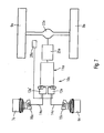
- a crawler vehicle 1 of which only parts of the sub-vehicle in Fig. 1 2 are shown with a frame 3 in principle, comprises two caterpillars 4 and 5 with associated front and rear drive and deflection wheels 6 and 7 or 8 and 9.
- the tracks 3 and 4 are preferably rubber tracks. You can also choose from another material. It is essential that they are on smooth, the traction non-positively transmitting drive and deflection wheels 6 - 9 are arranged.
- the drive 10 of the crawler vehicle 1 comprises a drive motor 11, which is also arranged on the frame 3.
- the drive motor 11 is expediently an internal combustion engine.
- a pump 12 is included the drive motor 11 connected via a shaft 13 and generates hydraulic Energy used to power drive units 15 and 16 or 17 and 18 serve.
- the hydraulic lines 14 lead on the one hand from the pump 12 to all drive units 15-18 and further hydraulic lines 14 'in turn lead from the drive units 15 - 18 back to the pump 12.
- the four drive units 15-18 are hydraulic motors that feed the Convert hydraulic energy into rotational energy and with Deliver using a shaft 19 to the drive and guide wheels 6 - 9.
- a reduction 20 / a reduction gear is also required assigned to each drive unit 15-18, as is also the case schematically emerges from Fig. 1.
- the front are Drive and deflection wheels 6 and 7 and the rear drive and deflection wheels 8 and 9 each of the same size.
- A are the same size or diameter not mandatory. So the front drive and Deflection wheels 6 and 7 may be significantly smaller than the rear ones Drive and deflection wheels 8 and 9, as the schematic diagram 3 shows.
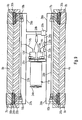
- 4-6 show a drive and deflection wheel in three views from the front and back or from the side. It is 5, a centrally arranged groove 21 or a circumferential groove for secure guidance of the caterpillar 4 or 5 to recognize.
- the groove-shaped recess 21 serves to receive a Longitudinal rib 22 on the drive and deflection wheels 6 - 9 assigned Side of the caterpillars 4, 5.
- FIGS. 7 and 8 schematically show an embodiment with a drive 10a, which is also a drive motor 11a in the form of a Comprises internal combustion engine.
- a drive 10a which is also a drive motor 11a in the form of a Comprises internal combustion engine.
- the drive motor 11a transmits in that shown in FIGS. 7 and 8 Embodiment the drive energy only mechanically on the two rear drive and deflection wheels 8a and 9a and the two caterpillars 4a and 5a.
- Common components such as gears, Differential and so on provided as drive elements and form drive units (differential 23a).
- the drive motor 11a drives at least one and according to the exemplary embodiment two pumps 12a and 12a 'for generating hydraulic Energy.
- the two hydraulic motors also suitably belong Reduction gears or reduction gear, since the two front drive and deflection wheels 6a and 7a a smaller diameter have as the rear drive and deflection wheels 8a and 9a.
- the invention is not based on mechanical and / or hydraulic drives limited. Instead of a hydraulic drive is alike an electric drive suitable for realizing the invention. But also a drive only with the help of an internal combustion engine and Without the use of hydraulic components, this is possible the invention. These variants are neither in the description explained in more detail in the figures, but in principle possible and for this reason are based on the inventive idea detected.
- the invention is not only suitable for use in construction vehicles, but especially in agricultural vehicles (Tractors). Above all, there is also the fact that both new, Vehicles with caterpillars with the four-wheel drive according to the invention can be equipped as well as that already in use Vehicles with the drive units according to the invention the front idler wheels added or added later can be.
- pump 12 or the pumps 12a, 12a 'in connection with the associated hydraulic lines 14a and the necessary Valves and control devices as well as with the drive units 15a and 16a serving hydraulic motors including gears on the front drive and deflection wheels 6a and 7a can be used as Parts of a retrofit unit for tracked vehicles already in use of the type of interest here.
- the special connection of the drive units is of particular importance for the front drive and deflection wheels in particular low driving speeds.
- the connection is at high driving speeds usually meaningless.
- the control of the Drives for the front drive and deflection wheels are therefore preferably electrically or electronically controlled only at low speeds of the drive and deflection wheels and if necessary then when different track speeds are caused by slipping available.
- the drive units 15-18 are in the case of that shown in FIG Example of execution also hydraulic motors as in the case of the drive units 15a and 16a of the embodiment shown in FIGS. 7 and 8. Since the rear drive and deflection wheels 8a and 9a (FIGS. 7 and 8) a mechanical power transmission with a differential 23, are preferably not shown there in the figures Brakes provided. This applies in particular to the Case of a conversion from a tractor to a caterpillar vehicle.
- a gear 25a and a joystick are respectively Steering wheel 28a provided and shown schematically in FIGS. 7 and 8, just as this applies to a ring gear 29 in FIG. 5.
- the tracked vehicle according to FIG. 9 has two tracks 4b and 5b which via drive and deflection wheels 6b and 7b or 8b and 9b circulate.
- the drive motor 11b is provided with a blower 24b and drives two pumps 12b and 12b 'via a gear 25b.
- a hydraulic line 14b to the left distribution line 26b connected to the left-hand drive units 15b and 17b (hydraulic motors) connected.
- the pump 12b 'a hydraulic line 14b to a right distribution line 27b, to the right-hand drive units 16b and 18b (hydraulic motors) connected.
- the pumps 12b, 12b ' is a joystick or steering wheel 28b assigned to the two if necessary (cornering) Pumps 12b and 12b 'with different performance and thus the left-hand and right-hand drive units with different To drive speed.
- the drive units 15b - 18b each have a reduction 20b and a ring gear 29b in drive engagement with the drive and Deflection wheels 6b - 9b.
- Each drive and deflection wheel 6b - 9b is one Multi-disc brake 30b assigned, which is hydraulically actuated.
- To is a hydraulic pump to the transmission 25b via a pump shaft 31b 32b connected.
- the hydraulic pump 32b which is a reservoir 33b for hydraulic fluid is assigned via a main brake line 34b connected to a brake selection device 35b, from the hydraulic brake lines 36b, 37b, 38b and 39b to the guide individual multi-disc brakes 30b.
- a left-sided respectively right-hand braking of the drive and deflection wheels 6b and 8b or 7b and 9b supports the one described above Steering by means of the joystick or steering wheel 28b.
- braking devices are not shown, however, corresponding braking devices can be used as shown in FIG 9 can be provided.
Landscapes
- Engineering & Computer Science (AREA)
- Chemical & Material Sciences (AREA)
- Combustion & Propulsion (AREA)
- Transportation (AREA)
- Mechanical Engineering (AREA)
- Motor Power Transmission Devices (AREA)
- Tires In General (AREA)
- Arrangement Or Mounting Of Propulsion Units For Vehicles (AREA)
- Harvesting Machines For Specific Crops (AREA)
Applications Claiming Priority (4)
| Application Number | Priority Date | Filing Date | Title |
|---|---|---|---|
| DE10222602 | 2002-05-17 | ||
| DE10222602 | 2002-05-17 | ||
| DE10224658A DE10224658A1 (de) | 2002-05-17 | 2002-06-03 | Raupenfahrzeug |
| DE10224658 | 2002-06-03 |
Publications (2)
| Publication Number | Publication Date |
|---|---|
| EP1362773A2 true EP1362773A2 (fr) | 2003-11-19 |
| EP1362773A3 EP1362773A3 (fr) | 2004-01-28 |
Family
ID=29271598
Family Applications (1)
| Application Number | Title | Priority Date | Filing Date |
|---|---|---|---|
| EP03010332A Ceased EP1362773A3 (fr) | 2002-05-17 | 2003-05-08 | Système de propulsion pour véhicules à chenilles |
Country Status (3)
| Country | Link |
|---|---|
| US (1) | US7086490B2 (fr) |
| EP (1) | EP1362773A3 (fr) |
| CA (1) | CA2426234A1 (fr) |
Cited By (5)
| Publication number | Priority date | Publication date | Assignee | Title |
|---|---|---|---|---|
| WO2008010033A1 (fr) * | 2006-07-12 | 2008-01-24 | Laurini Officine Meccaniche S.R.L. | Machine de dépose de tuyaux |
| WO2011029590A2 (fr) | 2009-09-11 | 2011-03-17 | Macmoter S. P. A. | Véhicule à chenilles |
| EP2264245A3 (fr) * | 2009-06-02 | 2014-11-05 | Smg Sportplatzmaschinenbau Gmbh | Finisseuse |
| CN104507786A (zh) * | 2012-07-24 | 2015-04-08 | 卡特彼勒公司 | 履带驱动系统和方法 |
| WO2017125425A1 (fr) * | 2016-01-19 | 2017-07-27 | Meister, Claudia | Véhicule de transport à chenilles |
Families Citing this family (15)
| Publication number | Priority date | Publication date | Assignee | Title |
|---|---|---|---|---|
| CA2463044A1 (fr) * | 2004-04-02 | 2005-10-02 | H. William B. Wilt | Methode de montage d'un vehicule modulaire, et vehicule modulaire |
| CA2489686A1 (fr) * | 2004-12-17 | 2006-06-17 | H. William B. Wilt | Vehicule de transport avec espace longitudinal de chargement s'etendant sur toute la longueur du vehicule |
| US20100072813A1 (en) * | 2007-01-16 | 2010-03-25 | Mcrae Brian Donald | Crawler Tracks and Idlers for Crawler Tracks |
| DE102006016728B4 (de) * | 2006-04-05 | 2009-04-16 | Terex-Demag Gmbh | Mehrfachantrieb für Raupenfahrwerk |
| DE202006009862U1 (de) * | 2006-06-23 | 2007-10-25 | Liebherr-Werk Nenzing Gmbh, Nenzing | Kettenfahrwerk |
| CA2569900C (fr) * | 2006-11-30 | 2014-01-07 | Ryan Fairhead | Vehicule |
| US7967087B2 (en) * | 2008-06-27 | 2011-06-28 | Caterpillar Sarl | Suspension for a machine |
| US8371403B2 (en) * | 2009-08-04 | 2013-02-12 | Travis Underwood | Tracked mobility device |
| US8783392B2 (en) | 2009-08-04 | 2014-07-22 | Freedom One Mobility Llc | Tracked mobility device |
| US20110108332A1 (en) * | 2009-11-12 | 2011-05-12 | Torvec, Inc. | Dual-Sprocket Track Drive |
| ITMI20132179A1 (it) * | 2013-12-20 | 2015-06-21 | Snowgrolic S A R L | Dispositivo di supporto per un veicolo cingolato e veicolo cingolato comprendente tale dispositivo di supporto |
| CA2964583A1 (fr) * | 2014-10-15 | 2016-04-21 | Dosso S.R.L. | Chenillette a fonctionnalite amelioree |
| CN106114665A (zh) * | 2016-06-30 | 2016-11-16 | 长春工业大学 | 一种履带车辆负重轮及个数的分布方法 |
| USD1003772S1 (en) | 2021-10-14 | 2023-11-07 | Trackmaster, LLC | Chassis for a tracked mobility device |
| CN120921900B (zh) * | 2025-10-15 | 2026-01-23 | 四川省农业机械科学研究院 | 一种小型履带式拖拉机动力底盘系统 |
Citations (1)
| Publication number | Priority date | Publication date | Assignee | Title |
|---|---|---|---|---|
| US6240661B1 (en) * | 1998-03-11 | 2001-06-05 | Harnischfeger Technologies, Inc. | Method and apparatus for replacing internal splines in a power mining shovel drive train |
Family Cites Families (18)
| Publication number | Priority date | Publication date | Assignee | Title |
|---|---|---|---|---|
| US2878883A (en) | 1956-03-28 | 1959-03-24 | Utah Scient Res Foundation | Vehicle and steerable endless tread therefor |
| US3645349A (en) * | 1970-01-05 | 1972-02-29 | David E Nichter | Drive for a reduced scale track-laying utility vehicle |
| US3792745A (en) | 1972-03-10 | 1974-02-19 | Rexnord Inc | Steering system for tool-carrying vehicle |
| US4207969A (en) * | 1974-01-14 | 1980-06-17 | Robert Howell Industries | Wet disc friction device |
| US3872939A (en) * | 1974-02-21 | 1975-03-25 | Harnischfeger Corp | Modular final drive for track type vehicles |
| US4000784A (en) * | 1975-04-24 | 1977-01-04 | The Manitowoc Company, Inc. | Demountable self-propelled crane transport assembly |
| US4069884A (en) * | 1975-04-24 | 1978-01-24 | The Manitowoc Company, Inc. | Self-propelled drive mechanism |
| FR2461632A1 (fr) * | 1979-07-24 | 1981-02-06 | Poclain Sa | Dispositif d'entrainement d'une chenille |
| US4519465A (en) * | 1982-03-26 | 1985-05-28 | Triplett Richard A | Track type four sprocket wheel drive crawler tractor |
| US4579182A (en) | 1983-02-28 | 1986-04-01 | Mckay International Engineers | Steerable, track-type vehicle for bulky loads |
| US4739852A (en) * | 1986-10-23 | 1988-04-26 | Caterpillar Inc. | Final drive mechanism for a vehicle |
| US4823852A (en) * | 1987-02-05 | 1989-04-25 | Allied Systems Company | Tree feller-buncher |
| US4942934A (en) * | 1988-03-17 | 1990-07-24 | Deere & Company | Belted crawler having auxiliary drive wheel |
| US4986377A (en) * | 1988-03-17 | 1991-01-22 | Deere & Company | Belted crawler having auxiliary drive |
| DE19537945C2 (de) * | 1995-10-12 | 2000-07-20 | Mak System Gmbh | Kettenfahrzeug |
| US6047785A (en) * | 1998-04-02 | 2000-04-11 | Blaw-Knox Construction Equip. Corp. | Mobile construction vehicle driven by track assemblies using continuous elastomeric belts |
| US6030058A (en) * | 1998-04-02 | 2000-02-29 | Blaw-Knox Construction Equipment Corporation | Mobile construction vehicle driven by track assemblies using continuous elastomeric belts |
| DE10033261A1 (de) | 2000-07-11 | 2002-01-24 | Macmoter Spa | Fahrzeug |
-
2003
- 2003-04-22 CA CA002426234A patent/CA2426234A1/fr not_active Abandoned
- 2003-05-07 US US10/434,293 patent/US7086490B2/en not_active Expired - Fee Related
- 2003-05-08 EP EP03010332A patent/EP1362773A3/fr not_active Ceased
Patent Citations (1)
| Publication number | Priority date | Publication date | Assignee | Title |
|---|---|---|---|---|
| US6240661B1 (en) * | 1998-03-11 | 2001-06-05 | Harnischfeger Technologies, Inc. | Method and apparatus for replacing internal splines in a power mining shovel drive train |
Cited By (9)
| Publication number | Priority date | Publication date | Assignee | Title |
|---|---|---|---|---|
| WO2008010033A1 (fr) * | 2006-07-12 | 2008-01-24 | Laurini Officine Meccaniche S.R.L. | Machine de dépose de tuyaux |
| EA014149B1 (ru) * | 2006-07-12 | 2010-10-29 | Лаурини Оффичине Мекканике С.Р.Л. | Трубоукладочная машина |
| US7845503B2 (en) | 2006-07-12 | 2010-12-07 | Laurini Officine Meccaniche S.R.L. | Pipe-laying machine |
| EP2264245A3 (fr) * | 2009-06-02 | 2014-11-05 | Smg Sportplatzmaschinenbau Gmbh | Finisseuse |
| WO2011029590A2 (fr) | 2009-09-11 | 2011-03-17 | Macmoter S. P. A. | Véhicule à chenilles |
| DE102009040929A1 (de) | 2009-09-11 | 2011-03-24 | Macmoter S.P.A., Modigliana | Raupenfahrzeug |
| WO2011029590A3 (fr) * | 2009-09-11 | 2011-05-05 | Macmoter S. P. A. | Véhicule à chenilles |
| CN104507786A (zh) * | 2012-07-24 | 2015-04-08 | 卡特彼勒公司 | 履带驱动系统和方法 |
| WO2017125425A1 (fr) * | 2016-01-19 | 2017-07-27 | Meister, Claudia | Véhicule de transport à chenilles |
Also Published As
| Publication number | Publication date |
|---|---|
| CA2426234A1 (fr) | 2003-11-17 |
| US7086490B2 (en) | 2006-08-08 |
| EP1362773A3 (fr) | 2004-01-28 |
| US20030226697A1 (en) | 2003-12-11 |
Similar Documents
| Publication | Publication Date | Title |
|---|---|---|
| EP1362773A2 (fr) | Système de propulsion pour véhicules à chenilles | |
| EP3079933B1 (fr) | Engin de travail automoteur | |
| EP0304594A2 (fr) | Système de propulsion électromécanique pour véhicule à chenilles | |
| DE102018116077A1 (de) | Kettenfahrzeug | |
| EP1634756B1 (fr) | Ensemble d'entraînement | |
| DE19908958A1 (de) | Antriebsvorrichtung für Tandemachsen | |
| EP3034348B1 (fr) | Boîte de transfert destinée à répartir un couple sur au moins un premier et un second arbre primaire d'un véhicule automobile | |
| AT406569B (de) | Fahrwerk für ein schienenfahrzeug, insbesondere niederflurstrassenbahn | |
| DE10257063A1 (de) | Allradantrieb für Fahrzeuge | |
| DE102009051124B4 (de) | Antriebssystem für ein Elektroradfahrzeug | |
| DE10224658A1 (de) | Raupenfahrzeug | |
| DE4230534C2 (de) | Fahrzeugantrieb | |
| DE19756699A1 (de) | Antriebsanordnung für allradgetriebene Fahrzeuge | |
| EP2581255B1 (fr) | Entraînement de véhicule doté d'un moteur à combustion interne, boîte de transfert, véhicule roulant sur rails ou ne roulant pas sur rails, et procédé de fonctionnement d'un véhicule comportant un moteur à combustion interne | |
| EP3472018A1 (fr) | Véhicule ferroviaire et procédé de commande d'un véhicule ferroviaire | |
| DE4019827C2 (fr) | ||
| EP1185807A1 (fr) | Systeme d'entrainement hydrostatique | |
| DE2053698A1 (de) | Steuereinrichtung für eine hydrostatisch angetriebene Überlagerungslenkung von Kettenfahrzeugen | |
| DE10314956B4 (de) | Überlagerungs-Lenkgetriebe, insbesondere für Gleiskettenfahrzeuge | |
| DE10017901A1 (de) | Hydrostatischer Fahrantrieb | |
| EP1199237A1 (fr) | Transmission pour véhicule ferroviaire | |
| DE2915964A1 (de) | Langsam fahrbares fahrzeug mit arbeitsgeraet | |
| DE2145773A1 (de) | Getriebeanordnung in kraftfahrzeugen, insbesondere landwirtschaftlich genutzten fahrzeugen | |
| DE102019208344B4 (de) | Land- oder bauwirtschaftlich nutzbare Arbeitsmaschine | |
| EP3513996B1 (fr) | Véhicule, en particulier véhicule agricole |
Legal Events
| Date | Code | Title | Description |
|---|---|---|---|
| PUAI | Public reference made under article 153(3) epc to a published international application that has entered the european phase |
Free format text: ORIGINAL CODE: 0009012 |
|
| AK | Designated contracting states |
Kind code of ref document: A2 Designated state(s): AT BE BG CH CY CZ DE DK EE ES FI FR GB GR HU IE IT LI LU MC NL PT RO SE SI SK TR |
|
| AX | Request for extension of the european patent |
Extension state: AL LT LV MK |
|
| PUAL | Search report despatched |
Free format text: ORIGINAL CODE: 0009013 |
|
| AK | Designated contracting states |
Kind code of ref document: A3 Designated state(s): AT BE BG CH CY CZ DE DK EE ES FI FR GB GR HU IE IT LI LU MC NL PT RO SE SI SK TR |
|
| AX | Request for extension of the european patent |
Extension state: AL LT LV MK |
|
| RIC1 | Information provided on ipc code assigned before grant |
Ipc: 7B 60K 17/356 B Ipc: 7B 62D 55/06 A |
|
| 17P | Request for examination filed |
Effective date: 20040514 |
|
| 17Q | First examination report despatched |
Effective date: 20040722 |
|
| AKX | Designation fees paid |
Designated state(s): AT BE BG CH CY CZ DE DK EE ES FI FR GB GR HU IE IT LI LU MC NL PT RO SE SI SK TR |
|
| APBN | Date of receipt of notice of appeal recorded |
Free format text: ORIGINAL CODE: EPIDOSNNOA2E |
|
| APAI | Date of receipt of notice of appeal modified |
Free format text: ORIGINAL CODE: EPIDOSCNOA2E |
|
| APAX | Date of receipt of notice of appeal deleted |
Free format text: ORIGINAL CODE: EPIDOSDNOA2E |
|
| APBN | Date of receipt of notice of appeal recorded |
Free format text: ORIGINAL CODE: EPIDOSNNOA2E |
|
| APBR | Date of receipt of statement of grounds of appeal recorded |
Free format text: ORIGINAL CODE: EPIDOSNNOA3E |
|
| APAF | Appeal reference modified |
Free format text: ORIGINAL CODE: EPIDOSCREFNE |
|
| APAK | Date of receipt of statement of grounds of an appeal modified |
Free format text: ORIGINAL CODE: EPIDOSCNOA3E |
|
| APBT | Appeal procedure closed |
Free format text: ORIGINAL CODE: EPIDOSNNOA9E |
|
| STAA | Information on the status of an ep patent application or granted ep patent |
Free format text: STATUS: THE APPLICATION HAS BEEN REFUSED |
|
| 18R | Application refused |
Effective date: 20081114 |