EP1362779B1 - Motorradartiges Fahrzeug - Google Patents
Motorradartiges Fahrzeug Download PDFInfo
- Publication number
- EP1362779B1 EP1362779B1 EP20030253106 EP03253106A EP1362779B1 EP 1362779 B1 EP1362779 B1 EP 1362779B1 EP 20030253106 EP20030253106 EP 20030253106 EP 03253106 A EP03253106 A EP 03253106A EP 1362779 B1 EP1362779 B1 EP 1362779B1
- Authority
- EP
- European Patent Office
- Prior art keywords
- vehicle
- motorcycle
- suspension
- wheel
- dampers
- Prior art date
- Legal status (The legal status is an assumption and is not a legal conclusion. Google has not performed a legal analysis and makes no representation as to the accuracy of the status listed.)
- Expired - Lifetime
Links
Images


Classifications
-
- B—PERFORMING OPERATIONS; TRANSPORTING
- B60—VEHICLES IN GENERAL
- B60G—VEHICLE SUSPENSION ARRANGEMENTS
- B60G21/00—Interconnection systems for two or more resiliently-suspended wheels, e.g. for stabilising a vehicle body with respect to acceleration, deceleration or centrifugal forces
- B60G21/02—Interconnection systems for two or more resiliently-suspended wheels, e.g. for stabilising a vehicle body with respect to acceleration, deceleration or centrifugal forces permanently interconnected
- B60G21/04—Interconnection systems for two or more resiliently-suspended wheels, e.g. for stabilising a vehicle body with respect to acceleration, deceleration or centrifugal forces permanently interconnected mechanically
- B60G21/05—Interconnection systems for two or more resiliently-suspended wheels, e.g. for stabilising a vehicle body with respect to acceleration, deceleration or centrifugal forces permanently interconnected mechanically between wheels on the same axle but on different sides of the vehicle, i.e. the left and right wheel suspensions being interconnected
-
- B—PERFORMING OPERATIONS; TRANSPORTING
- B60—VEHICLES IN GENERAL
- B60G—VEHICLE SUSPENSION ARRANGEMENTS
- B60G17/00—Resilient suspensions having means for adjusting the spring or vibration-damper characteristics, for regulating the distance between a supporting surface and a sprung part of vehicle or for locking suspension during use to meet varying vehicular or surface conditions, e.g. due to speed or load
- B60G17/015—Resilient suspensions having means for adjusting the spring or vibration-damper characteristics, for regulating the distance between a supporting surface and a sprung part of vehicle or for locking suspension during use to meet varying vehicular or surface conditions, e.g. due to speed or load the regulating means comprising electric or electronic elements
- B60G17/016—Resilient suspensions having means for adjusting the spring or vibration-damper characteristics, for regulating the distance between a supporting surface and a sprung part of vehicle or for locking suspension during use to meet varying vehicular or surface conditions, e.g. due to speed or load the regulating means comprising electric or electronic elements characterised by their responsiveness, when the vehicle is travelling, to specific motion, a specific condition, or driver input
- B60G17/0162—Resilient suspensions having means for adjusting the spring or vibration-damper characteristics, for regulating the distance between a supporting surface and a sprung part of vehicle or for locking suspension during use to meet varying vehicular or surface conditions, e.g. due to speed or load the regulating means comprising electric or electronic elements characterised by their responsiveness, when the vehicle is travelling, to specific motion, a specific condition, or driver input mainly during a motion involving steering operation, e.g. cornering, overtaking
-
- B—PERFORMING OPERATIONS; TRANSPORTING
- B60—VEHICLES IN GENERAL
- B60G—VEHICLE SUSPENSION ARRANGEMENTS
- B60G21/00—Interconnection systems for two or more resiliently-suspended wheels, e.g. for stabilising a vehicle body with respect to acceleration, deceleration or centrifugal forces
- B60G21/007—Interconnection systems for two or more resiliently-suspended wheels, e.g. for stabilising a vehicle body with respect to acceleration, deceleration or centrifugal forces means for adjusting the wheel inclination
-
- B—PERFORMING OPERATIONS; TRANSPORTING
- B60—VEHICLES IN GENERAL
- B60G—VEHICLE SUSPENSION ARRANGEMENTS
- B60G7/00—Pivoted suspension arms; Accessories thereof
- B60G7/001—Suspension arms, e.g. constructional features
-
- B—PERFORMING OPERATIONS; TRANSPORTING
- B62—LAND VEHICLES FOR TRAVELLING OTHERWISE THAN ON RAILS
- B62D—MOTOR VEHICLES; TRAILERS
- B62D9/00—Steering deflectable wheels not otherwise provided for
- B62D9/02—Steering deflectable wheels not otherwise provided for combined with means for inwardly inclining vehicle body on bends
-
- B—PERFORMING OPERATIONS; TRANSPORTING
- B62—LAND VEHICLES FOR TRAVELLING OTHERWISE THAN ON RAILS
- B62K—CYCLES; CYCLE FRAMES; CYCLE STEERING DEVICES; RIDER-OPERATED TERMINAL CONTROLS SPECIALLY ADAPTED FOR CYCLES; CYCLE AXLE SUSPENSIONS; CYCLE SIDECARS, FORECARS, OR THE LIKE
- B62K5/00—Cycles with handlebars, equipped with three or more main road wheels
- B62K5/10—Cycles with handlebars, equipped with three or more main road wheels with means for inwardly inclining the vehicle body on bends
-
- B—PERFORMING OPERATIONS; TRANSPORTING
- B60—VEHICLES IN GENERAL
- B60G—VEHICLE SUSPENSION ARRANGEMENTS
- B60G2200/00—Indexing codes relating to suspension types
- B60G2200/10—Independent suspensions
- B60G2200/13—Independent suspensions with longitudinal arms only
-
- B—PERFORMING OPERATIONS; TRANSPORTING
- B60—VEHICLES IN GENERAL
- B60G—VEHICLE SUSPENSION ARRANGEMENTS
- B60G2204/00—Indexing codes related to suspensions per se or to auxiliary parts
- B60G2204/10—Mounting of suspension elements
- B60G2204/12—Mounting of springs or dampers
- B60G2204/128—Damper mount on vehicle body or chassis
-
- B—PERFORMING OPERATIONS; TRANSPORTING
- B60—VEHICLES IN GENERAL
- B60G—VEHICLE SUSPENSION ARRANGEMENTS
- B60G2204/00—Indexing codes related to suspensions per se or to auxiliary parts
- B60G2204/40—Auxiliary suspension parts; Adjustment of suspensions
- B60G2204/422—Links for mounting suspension elements
-
- B—PERFORMING OPERATIONS; TRANSPORTING
- B60—VEHICLES IN GENERAL
- B60G—VEHICLE SUSPENSION ARRANGEMENTS
- B60G2206/00—Indexing codes related to the manufacturing of suspensions: constructional features, the materials used, procedures or tools
- B60G2206/01—Constructional features of suspension elements, e.g. arms, dampers, springs
- B60G2206/10—Constructional features of arms
- B60G2206/11—Constructional features of arms the arm being a radius or track or torque or steering rod or stabiliser end link
-
- B—PERFORMING OPERATIONS; TRANSPORTING
- B62—LAND VEHICLES FOR TRAVELLING OTHERWISE THAN ON RAILS
- B62K—CYCLES; CYCLE FRAMES; CYCLE STEERING DEVICES; RIDER-OPERATED TERMINAL CONTROLS SPECIALLY ADAPTED FOR CYCLES; CYCLE AXLE SUSPENSIONS; CYCLE SIDECARS, FORECARS, OR THE LIKE
- B62K5/00—Cycles with handlebars, equipped with three or more main road wheels
- B62K2005/001—Suspension details for cycles with three or more main road wheels
Definitions
- This Invention relates to motorcycle-type vehicles having, at at least one end of the vehicle, a pair of wheels which tilt with the vehicle.
- Such vehicles having a swing arm for each such wheel, the swing arms being pivotally mounted on the vehicle for angular movement about transverse pivotal axes, a damper for each swing arm together with a resilient connection, the two swing arms being interconnected by means for imposing corresponding movements of the swing arms in opposite directions and means selectively operable to lock the suspension.
- a vehicle according to the invention is characterized In that the selectively operable locking means comprise the dampers.
- the vehicle shown in Figs. 1 to 3 is of generally similar construction to those which form the subject of my co-pending International Application number WO 02/044008 .
- the vehicle has a main chassis 10 containing an engine and transmission (not shown).
- the chassis is supported on a road surface by means of two front wheels 11L and 11R and two rear wheels, 12L and 12R.
- the chassis is supported on the rear wheels 12L,R by swing arms 13L, 13R which are pivoted at 14 to the chassis 10 at their forward ends and carry stub shaft 15 at their rear ends on which the rear wheels are rotatably mounted.
- the rear swing arms 13 also carry road brakes (not shown).
- Each rear swing arm 13 carries an upstanding lug 16, the lug 16 being connected by pivoted links 17 to opposite ends of a balance beam 18 which is pivoted at 19 at its mid-point to a carriage 20 which is slidable along guide rods 21 under the control of a spring unit 22 the forward end of which is anchored at 23 to the chassis.
- the spring unit 22 may include a hydraulic ram as described in international application WO 02/044008 .
- the balance beam 18 turns on its pivot. If a dangerous situation arises in which the rider is about to lose control, relative angular movement between the rear swing arms 13 can be stopped or limited, either by engagement of the brake 22 or by the use of a separate damper D for each swing arm.
- the dampers can be interconnected through a valve which can be closed by a solenoid, or the working medium in the dampers can be of the kind which can be stiffened electrically.
- damper D Some residual suspension movement would be provided by including a resilient block or mounting at at least one end of each damper D.
- the dampers act between the beam ends and the chassis.
- the range of angular movement of the beam 18 about its pivot can be limited by stops acting between the beam 18 and its carriage 20. Even in one of such limit positions of the beam, full resilient suspension is still available.
- each front swing arm 31 is pivoted about an axis 32 to a bracket 33 on the chassis 10.
- each front swing arm 31 carries a ball joint 34 by which it is connected to the lower end of a king strut 35 about a centre of articulation 36.
- the chassis 10 includes a bridge portion 37 to which left and right upper wishbone frames 38L and 38R are pivotally mounted on transverse pivots having axes 39.
- each wishbone 38 is articulated by a ball joint 40 having a centre 41 to a lateral projection 42 ( Fig. 2 ) on the king strut 35.
- the lower end of the king strut 35 carries a stub shaft 43 on which the respective front wheel is rotatably mounted (together with a suitable brake).
- the ball joint centres 36 and 41 thus define the equivalent to a king pin axis 44. As can be seen from Fig. 3 , this intersects the plane 45 through the axes 32 and 39 at a point above the front wheel.
- a plane 46 through the axis 32 and ball-joint centre 36 intersects a plane 47 through the axis 39 and the ball-joint centre 41 at a line 48 to the rear of the front suspension.
- the front swing arms are connected by pivoted links 51 to opposite ends of a front balance beam 52, pivotally mounted about a vertical axis to a carriage 53, slidable on guide rods 54 under the action of a spring unit 55.
- individual dampers D can be interconnected between the front swing arms 31 and the chassis 10 as described above in respect of the rear swing arms and angular movement of the balance beam 52 relative to its carriage 53 is limited by stops.
- Each front wheel is steered by turning the king strut 35 about the axis 44.
- the upper end of the king strut carries a ball joint 61 which articulates the front end of a drag link 62, the rear end of which is connected by a ball-joint 63 to a bell crank 64 pivoted on the bridge 37, the other arms of the bell crank 64 being connected by links 65 to an arm 66 on a handlebar assembly 67, supported for rotation in the bridge 37.
- the chassis 10 Towards the rear, the chassis 10 carries a pillar 71 supporting a seat 72.
- Figs. 4a to 4d represent the vehicle's front left wheel and king-pin viewed from the front.
- Fig. 4a shows the steering axis 60 located through the wheel's centre line, but variations from this position are likely to be beneficial.
- the steering axis 61 has a positive offset, i.e., moved inboard away from the wheel's centre line 60. This would allow more room within the narrow confines of a motorcycle / scooter wheel-hub for components such as the brake and wheel bearing, and make the steering lighter when stationary, which might be significant given the traffic negotiating abilities of the vehicle and the large steering angles needed to get around stationary traffic.
- This last aspect is due to more of the tyre contact patch being able to rotate around the steering axis 61 instead of being subject to tyre scrub.
- Fig. 4c shows negative offset which would still allow more of the tyre contact patch to be able to rotate around the steering axis 62 as in Fig. 4b , but would also help to keep the vehicle in a straight line during a front tyre blow-out or braking when differing levels of grip are encountered between the left and right sides of the vehicle.
- This last aspect works in this way: the rolling resistance of a flat tyre is greater than when it was inflated, consequently the vehicle will pull towards the side of the vehicle with the flat tyre.
- this tendency is countered by the negative offset because the centre of the wheel's centre line lies on the inside of the offset.
- This drag effect caused by either a positive or a negative offset could also be used to take in the combined clearances of the steering joints that might be an issue with this type of steering. For instance, if a positive offset was used, the front wheels could point towards each other slightly, or toe-in, when the vehicle was stationary and if a negative offset was used, the front wheels could point away from each other or toe-out. In both instances, the wheels would resume a straight ahead position when the vehicle was moving by the rolling resistance taking up the combination of small clearances in the steering.
- Fig. 4d shows the king-pin inwardly inclined at its top which allows extra room for wheel-hub components; as in Fig. 4b lighter stationary steering; as in Figs. 4b and 4c ; and the additional stability during braking, etc. as in Fig. 4c .
- a further aspect of this inwardly inclined king-pin is that as the steering turns the vehicle will tend to lift and thereby act against gravity. Consequently, gravity will try to return the vehicle's rider's mass back to the lowest possible position. The effect of this is to self-align the steering which could aid the steering self-alignment created by the trail, or be sufficient to eliminate the need for trail altogether.
- the king-pin could be inclined the other way if need be.
- Fig. 5a shows a negative camber angle with the wheels inwardly inclined. This would make the distance across the top of the wheels smaller and thereby allow any wheel-covering fairing to be narrower than if the wheels were upright, which keeps the vehicle as narrow as possible to help it get through traffic. Furthermore, when negotiating a bend the inside wheel will be more upright than the outside wheel which could help grip should the vehicle lose grip during the bend. This is due to the resultant force reducing its angle from the vertical when a loss in grip is experienced which makes the weight bear more on the wheels that are on the inside of the bend, especially with the engagement of the suspension brake.
- Fig. 5b shows a positive camber angle with the wheels outwardly inclined. This would create more room for wheel-hub components, and makes the inside wheel in a bend lean more which makes the 'rolling-cone' effect of the inside wheel greater than the outside wheel. This last aspect may be beneficial as the inside wheel has to turn more than the outside wheel anyway.
- the 'rolling cone' effect ( Fig. 6 ) is to do with rounded tyre profiles which results in the tyre's centre travelling faster than the tyre's edge. This is because the tyre's centre has a greater diameter than the tyre's edge. Therefore, if such a tyre was inclined at a reasonable angle but travelling in a straight line the edge of the tyre would scrub as the tyre's centre grips. This drag promotes a turning motion so that the smaller diameter tyre edge can travel around a smaller circle than the tyre's centre, and thereby reduce the drag. The greater the inclination of the tyre the smaller the circle it wants to turn around. This aspect could also be used for the rear wheels.
- the front and rear slip angles can be altered to redress understeer or oversteer, especially with flatter profile tyres.
- the stub axle for the wheel is shown in line with the bottom king-pin joint.
- the stub axle could be:
- Fig. 7a the vehicle is in line with the resultant force whilst negotiating a bend.
- Fig. 7b the vehicle loses grip and the resultant force drops off.
- Figs. 7b and 7c the inside leading and trailing arms have been locked up, which moves the point of the vehicle's lateral rotation from the centre of the vehicle to the contact area of the vehicle's wheels which are on the inside of the bend.
- the hydraulic ram lowers the suspension assembly which can only act on the unlocked suspension arms which leads to realignment as shown in Fig. 7c .
- the ram could stop moving, the locked leading and trailing arms could be released and the ram raise the vehicle again, the unlocked leading and trailing arms could be locked up as well until the vehicle reduces speed to a pre-determined amount or until the system was manually over-ridden by the manual control lever.
- Fig. 7d the vehicle is in line with the resultant force whilst negotiating a bend.
- Fig. 7e the vehicle unexpectedly turns sharper into a bend, which may follow an initial losing of grip and the resultant force increases.
- the outside leading and trailing arms have been locked up which moves the point of the vehicle's lateral rotation from the centre of the vehicle to the contact area of the vehicle's wheels which are on the outside of the bend.
- the hydraulic ram lowers the suspension assembly which can only act on the unlocked suspension arms which leads to the position shown in Fig. 7f , that is realignment, or just by an amount sufficient to keep the resultant force within the vehicle's footprint.
- the suspension arms were braked by means of a brake quadrant mounted on, for instance, each left suspension arm journal and a brake caliper mounted on each right suspension arm journal.
- a brake quadrant mounted on, for instance, each left suspension arm journal and a brake caliper mounted on each right suspension arm journal.
- To utilise such an arrangement in the above context would require four brake calipers and four brake quadrants in addition to the four brake discs and four brake calipers needed for the wheels.
- a potentially better way is to have a separate damper for each leading and trailing arm which could be electrochemically stiffened at the required moment.
- a solenoid activated valve could shut off the oil flow through the dampers to prevent further movement taking place.
- the side view of the leading arm could be represented with just a line running from the stub axle axis to the leading arm journal axis.
- the next diagram shows this line as the side elevation of the leading arm with the line below it as the plan view and the view to the right as the front view, all drawn in first angle projection.
- the interrupted line shows the leading arm axis of rotation.
- this axis of rotation does not have to be completely laterally located, instead the leading arms could be semi-leading as some angular movement either side of the true lateral position may be beneficial. For instance, with the axis angled outward (positively), the leading arms would tend to move towards each other as they rise and fall.
- the contact patch of the tyres would tend to move away from each other as the leading arms rise, or move towards each other as they fall.
- the effect of this when the vehicle is leaning around a bend is that the wheels remain more upright which would allow flatter section tyres and thereby more grip, the vehicle footprint moves towards the inside of the bend which may be desired, during heavy braking without an anti-dive arrangement the front track would tend to get wider and thereby generate a bit more stability.
- the axis pointing the other way (negative) the vehicle's footprint is moved towards the outside of a bend which may be desired.
- a positive or negative leading arm arrangement may also be required to achieve an overall suitable steering and suspension geometry.
- leading arm axis is angled in either direction from the true vertical which might also be necessary to achieve an overall suitable steering and suspension geometry.
- Lateral and vertical movement for the leading arm journal axis or combinations can also be applied to the back of the vehicle to form semi-trailing arms. Apart from the reasons given above the variations can alter the vehicle's 'roll centre' at either end of the vehicle which can influence the way the vehicle behaves during a bend.
- the upper arm journal axis could be aligned from the true lateral and vertical positions, or a combination of the two, as could the drag link, to achieve an overall suitable steering and suspension geometry.
- the locking means may be responsive to a sensor including a pendulum with light damping such that the pendulum can follow normal lateral tilting of the vehicle but cannot follow abnormal movements and this can operate appropriate switch and / or valve means.
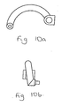
- the vehicle may have either one or two front wheels to each of which is attached a J or C shaped front swing arm forming part of a quadrilateral linkage.
- This swing arm could be inclined at an angle (see Figs. 10a and 10b ) to help keep the vehicle's centre of gravity low, whilst also allowing wheel clearance as in the previous embodiment.
Landscapes
- Engineering & Computer Science (AREA)
- Mechanical Engineering (AREA)
- Chemical & Material Sciences (AREA)
- Combustion & Propulsion (AREA)
- Transportation (AREA)
- Vehicle Body Suspensions (AREA)
- Axle Suspensions And Sidecars For Cycles (AREA)
Claims (6)
- Fahrzeug vom Motorradtyp, das an wenigstens einem Ende des Fahrzeugs ein Paar Räder, die mit dem Fahrzeug geneigt werden, eine Schwinge (13 oder 31) für jedes genannte Rad, wobei die Schwingen zur Winkelbewegung um transversale Drehachsen drehbar am Fahrzeug montiert sind, einen Stoßdämpfer (D) für jede Schwinge, wobei jeder Dämpfer die ihm zugeordnete Schwinge zusammen mit einer federnden Verbindung mit dem Fahrzeug verbindet, wobei die zwei Schwingen mit Einrichtungen (18 oder 52) zum Ausüben entsprechender Bewegungen der Schwingen in entgegengesetzten Richtungen miteinander verbunden sind, und Einrichtungen zum selektiven Blockieren der Federung hat, dadurch gekennzeichnet, dass die Blockiereinrichtungen die Dämpfer (D) beinhalten.
- Fahrzeug vom Motorradtyp nach Anspruch 1, dadurch gekennzeichnet, dass die Blockiereinrichtungen die Bewegung des Arbeitsmediums in den Stoßdämpfern (D) blockieren.
- Fahrzeug vom Motorradtyp nach Anspruch 2, bei dem die Stoßdämpfer durch ein Ventil miteinander verbunden sind, das von einem Elektromagnet geschlossen werden kann.
- Fahrzeug vom Motorradtyp nach Anspruch 1 oder 2, bei dem das Arbeitsmedium in den Stoßdämpfern elektrisch versteifbar ist.
- Fahrzeug vom Motorradtyp nach einem der vorhergehenden Ansprüche, bei dem an wenigstens einem Ende jedes Stoßdämpfers eine federnde Einrichtung eingebaut ist, um bei Aktivieren der Blockiereinrichtungen eine Restfederungsbewegung zu ergeben.
- Fahrzeug vom Motorradtyp nach einem der vorhergehenden Ansprüche, das vorne ein genanntes Räderpaar hat, wobei für jedes Rad von der Schwinge (31), einem oberen Lenker (38), der für Winkelbewegungen um eine Querachse des Fahrzeugs drehbar an einem hinteren Ende montiert ist, und einem Federbein (35), das an seinem oberen Ende an den oberen Lenker (38) und an seinem unteren Ende an der Schwinge angelenkt ist, eine Viergelenkkette gebildet wird und ein Gestänge (62 bis 65) ein Lenkungssteuerelement (67) mit jedem Federbein (35) verbindet.
Applications Claiming Priority (6)
| Application Number | Priority Date | Filing Date | Title |
|---|---|---|---|
| GB0211399 | 2002-05-17 | ||
| GB0211399A GB0211399D0 (en) | 2002-05-17 | 2002-05-17 | Motorcycle-type vehicles |
| GB0222385 | 2002-09-27 | ||
| GB0222385A GB0222385D0 (en) | 2002-05-17 | 2002-09-27 | Suspension dampers |
| GB0306023 | 2003-03-17 | ||
| GB0306023A GB0306023D0 (en) | 2002-05-17 | 2003-03-17 | Suspension stop |
Publications (3)
| Publication Number | Publication Date |
|---|---|
| EP1362779A2 EP1362779A2 (de) | 2003-11-19 |
| EP1362779A3 EP1362779A3 (de) | 2006-04-12 |
| EP1362779B1 true EP1362779B1 (de) | 2011-04-20 |
Family
ID=29273347
Family Applications (1)
| Application Number | Title | Priority Date | Filing Date |
|---|---|---|---|
| EP20030253106 Expired - Lifetime EP1362779B1 (de) | 2002-05-17 | 2003-05-19 | Motorradartiges Fahrzeug |
Country Status (1)
| Country | Link |
|---|---|
| EP (1) | EP1362779B1 (de) |
Families Citing this family (23)
| Publication number | Priority date | Publication date | Assignee | Title |
|---|---|---|---|---|
| AT413524B (de) * | 2003-11-21 | 2006-03-15 | Berghofer Alfred | Vorderradaufhängung für ein zwei- oder dreirad |
| DE602006009391D1 (de) * | 2006-07-26 | 2009-11-05 | Yamaha Motor Europ | Motorrad |
| EP2046589B1 (de) * | 2006-07-28 | 2010-04-28 | Marabese Design S.r.l. | System zur steuerung des trimms von motorrädern mit drei oder vier rädern |
| EP2099624A1 (de) * | 2006-12-01 | 2009-09-16 | The Four Wheeled Motorcycle Company Limited | Aufhängungssystem |
| GB2444250A (en) * | 2006-12-01 | 2008-06-04 | Nicholas Richard Shotter | Hydraulic damper system for a leanable vehicle |
| EP2628672B1 (de) * | 2009-09-08 | 2017-04-19 | Ino8 Pty Ltd | Kippsteuerung für Kippfahrzeug |
| CN102616318B (zh) * | 2012-04-05 | 2013-06-05 | 太仓市车中宝休闲用品有限公司 | 叉形折叠摆臂滑板车 |
| CN102774460B (zh) * | 2012-07-27 | 2013-09-04 | 太仓市车中宝休闲用品有限公司 | X形滑板车 |
| CN103935435A (zh) * | 2014-04-28 | 2014-07-23 | 太仓市车中宝休闲用品有限公司 | 乐摇车 |
| DE102014209328A1 (de) * | 2014-05-16 | 2015-11-19 | Ford Global Technologies, Llc | Radaufhängung für ein Neigefahrwerk und Neigefahrwerk sowie Verfahren zu dessen Betrieb und entsprechend ausgestattetes Fahrzeug |
| DE202014102328U1 (de) | 2014-05-16 | 2014-06-10 | Ford Global Technologies, Llc | Radaufhängung für ein Neigefahrwerk und Neigefahrwerk |
| DE102014209329A1 (de) | 2014-05-16 | 2015-11-19 | Ford Global Technologies, Llc | Radaufhängung für ein Neigefahrwerk und Neigefahrwerk sowie Verfahren zu dessen Betrieb und entsprechend ausgestattetes Fahrzeug |
| CA2952358A1 (en) | 2014-06-20 | 2015-12-23 | Quadro Vehicles Sa | Improved control system of the trim of vehicles with more than two wheels |
| CA2953068A1 (en) | 2014-07-04 | 2016-01-07 | Riccardo Marabese | Electronic braking device of the tilting system of a vehicle with three or more tilting wheels |
| JP7182701B2 (ja) * | 2018-09-28 | 2022-12-02 | ピアッジオ エ チ.ソシエタ ペル アチオニ | 二重操舵棒を備えた二つの前輪を有する車両用の前輪部及び前記前輪部を備えた車両 |
| IT201800010942A1 (it) * | 2018-12-10 | 2020-06-10 | Piaggio & C Spa | Avantreno per veicolo a due ruote anteriori sterzanti e motoveicolo comprendente detto avantreno |
| JP7280657B2 (ja) * | 2019-07-30 | 2023-05-24 | カワサキモータース株式会社 | 走行車両 |
| JP7495228B2 (ja) * | 2019-12-26 | 2024-06-04 | カワサキモータース株式会社 | リーン型車両 |
| JP7430060B2 (ja) | 2019-12-26 | 2024-02-09 | カワサキモータース株式会社 | リーン型車両 |
| CN111252141B (zh) * | 2020-01-19 | 2024-07-30 | 北京星网精仪科技有限公司 | 具有减震及摆动转向操纵机构的双车体摆臂越障车 |
| CN111439332B (zh) * | 2020-04-22 | 2021-12-14 | 泉州台商投资区源祺工业设计有限公司 | 一种可提升电动三轮车转向稳定性的后轮安装机构 |
| DE102021203459B3 (de) | 2021-04-08 | 2022-08-25 | Zf Friedrichshafen Ag | Integration von Betriebsbremse, Feststellbremse und Kippsicherung |
| CN118790200B (zh) * | 2024-09-14 | 2024-12-17 | 昆明山螃海科技有限公司 | 一种车辆脱困装置及方法 |
Family Cites Families (9)
| Publication number | Priority date | Publication date | Assignee | Title |
|---|---|---|---|---|
| FR2522590A1 (fr) * | 1982-03-05 | 1983-09-09 | Jambon Jacques | Systeme de suspension pour vehicule a organes d'appui inclinables et vehicule s'y rapportant |
| FR2550507B1 (fr) * | 1983-08-11 | 1985-10-31 | Devaux Pierre | Tricycle motorise a roues arriere independantes |
| US4756379A (en) * | 1986-06-04 | 1988-07-12 | Honda Giken Kogyo Kabushiki Kaisha | Motorcycle |
| US4887829A (en) * | 1987-04-07 | 1989-12-19 | Prince Curtis L | Rear wheel suspension system for a tricycle vehicle |
| ES2064251B1 (es) * | 1993-01-04 | 1998-02-16 | Calleja Vidal Carlos | Balanceador articulado con eje oscilante y posibilidad de bloqueo. |
| IT1298902B1 (it) * | 1998-02-13 | 2000-02-07 | Inovo S N C Di Maurizio Ficcad | Telaio per veicolo con tre ruote in grado di inclinarsi durante le curve |
| SE522579C2 (sv) * | 2000-04-04 | 2004-02-17 | Yamaha Motor Co Ltd | Förfarande att medelst stödorgansarrangemang påverka ett fordons lutning samt fordon med sådant stödorgansarrangemang |
| GB0029136D0 (en) * | 2000-11-29 | 2001-01-10 | Shotter Nicholas R | Motorcycle-type vehicle |
| AT411166B (de) * | 2001-08-30 | 2003-10-27 | Hans Leeb Zweirad Handel Gmbh | Motorfahrzeug mit einem angetriebenen hinterrad und zwei gelenkten vorderrädern |
-
2003
- 2003-05-19 EP EP20030253106 patent/EP1362779B1/de not_active Expired - Lifetime
Also Published As
| Publication number | Publication date |
|---|---|
| EP1362779A3 (de) | 2006-04-12 |
| EP1362779A2 (de) | 2003-11-19 |
Similar Documents
| Publication | Publication Date | Title |
|---|---|---|
| EP1362779B1 (de) | Motorradartiges Fahrzeug | |
| US7850180B2 (en) | Hub assembly for a tilting vehicle suspension | |
| US6467783B1 (en) | Motor vehicle equipped with a system for controlling the camber of the wheels of the vehicle on a bend | |
| JP4456794B2 (ja) | キャンバ角変化を許容するサスペンション装置 | |
| US10464601B2 (en) | Automatic tilting vehicle | |
| JP3370662B2 (ja) | 車輌用サスペンション装置 | |
| US5415427A (en) | Wheel suspension system | |
| US20130214503A1 (en) | Devices To Let A Tilting Vehicle Lean When Driving And To Keep It Standing When Stopped | |
| EP2199195A1 (de) | Motorrad | |
| JP2009509857A (ja) | 傾斜サスペンションマシン | |
| US5257801A (en) | Independent wheel suspension apparatus for vehicle | |
| CN101792002A (zh) | 带有改进的整合转向和悬架系统的车辆 | |
| EP3403857A1 (de) | Aufhängungsvorrichtung für nichtgelenktes antriebsrad mit radmotor | |
| US11801892B2 (en) | Vehicle with tilt frame and spring damper system | |
| US5992868A (en) | Wheel suspension system having a high rigidity to side forces | |
| US5810383A (en) | Suspension and steering linkage for a tricycle | |
| EP1894753B1 (de) | Struktur um das Neigen unabhängig aufgehängter Räder mit der Fahrzeughülle zu ermöglichen | |
| EP2709862A2 (de) | Vorderes aufhängungssystem | |
| US5088570A (en) | Steerable rear dual axle system for large trucks | |
| KR910006830B1 (ko) | 캐스터(Castor) 콘트롤에 의한 앤티롤(Anti-roll) 메카니즘(Mechanism) | |
| EP2990319B1 (de) | Fahrzeug | |
| KR20040055736A (ko) | 차량용 서스펜션과, 차량의 휠 조립체용 서스펜션 및차량을 서스펜딩하는 방법 | |
| CN1697739B (zh) | 用于悬挂车辆的设备和方法 | |
| JPH054404Y2 (de) | ||
| CN121866203A (zh) | 车辆悬架平衡组件 |
Legal Events
| Date | Code | Title | Description |
|---|---|---|---|
| PUAI | Public reference made under article 153(3) epc to a published international application that has entered the european phase |
Free format text: ORIGINAL CODE: 0009012 |
|
| AK | Designated contracting states |
Kind code of ref document: A2 Designated state(s): AT BE BG CH CY CZ DE DK EE ES FI FR GB GR HU IE IT LI LU MC NL PT RO SE SI SK TR |
|
| AX | Request for extension of the european patent |
Extension state: AL LT LV MK |
|
| RIC1 | Information provided on ipc code assigned before grant |
Ipc: B62D 7/16 19680901ALI20051128BHEP Ipc: B62D 7/06 19680901ALI20051128BHEP Ipc: B60G 21/00 19680901ALI20051128BHEP Ipc: B62D 17/00 19680901ALI20051128BHEP Ipc: B62K 5/00 19680901AFI20030905BHEP Ipc: B60G 17/015 19900101ALI20051128BHEP |
|
| PUAL | Search report despatched |
Free format text: ORIGINAL CODE: 0009013 |
|
| AK | Designated contracting states |
Kind code of ref document: A3 Designated state(s): AT BE BG CH CY CZ DE DK EE ES FI FR GB GR HU IE IT LI LU MC NL PT RO SE SI SK TR |
|
| AX | Request for extension of the european patent |
Extension state: AL LT LV MK |
|
| 17P | Request for examination filed |
Effective date: 20061011 |
|
| AKX | Designation fees paid |
Designated state(s): AT BE BG CH CY CZ DE DK EE ES FI FR GB GR HU IE IT LI LU MC NL PT RO SE SI SK TR |
|
| 17Q | First examination report despatched |
Effective date: 20070215 |
|
| RAP1 | Party data changed (applicant data changed or rights of an application transferred) |
Owner name: SHOTTER, NICHOLAS RICHARD |
|
| RIN1 | Information on inventor provided before grant (corrected) |
Inventor name: SHOTTER, NICHOLAS RICHARD |
|
| RAP1 | Party data changed (applicant data changed or rights of an application transferred) |
Owner name: THE FOUR WHEELED MOTORCYCLE COMPANY LIMITED |
|
| RIN1 | Information on inventor provided before grant (corrected) |
Inventor name: NICK SHOTTER |
|
| GRAP | Despatch of communication of intention to grant a patent |
Free format text: ORIGINAL CODE: EPIDOSNIGR1 |
|
| GRAS | Grant fee paid |
Free format text: ORIGINAL CODE: EPIDOSNIGR3 |
|
| GRAA | (expected) grant |
Free format text: ORIGINAL CODE: 0009210 |
|
| AK | Designated contracting states |
Kind code of ref document: B1 Designated state(s): AT BE BG CH CY CZ DE DK EE ES FI FR GB GR HU IE IT LI LU MC NL PT RO SE SI SK TR |
|
| REG | Reference to a national code |
Ref country code: GB Ref legal event code: FG4D |
|
| REG | Reference to a national code |
Ref country code: CH Ref legal event code: EP |
|
| REG | Reference to a national code |
Ref country code: IE Ref legal event code: FG4D |
|
| REF | Corresponds to: |
Ref document number: 60336784 Country of ref document: DE Date of ref document: 20110601 Kind code of ref document: P |
|
| REG | Reference to a national code |
Ref country code: DE Ref legal event code: R096 Ref document number: 60336784 Country of ref document: DE Effective date: 20110601 |
|
| PGFP | Annual fee paid to national office [announced via postgrant information from national office to epo] |
Ref country code: ES Payment date: 20110621 Year of fee payment: 9 |
|
| REG | Reference to a national code |
Ref country code: NL Ref legal event code: VDEP Effective date: 20110420 |
|
| PGFP | Annual fee paid to national office [announced via postgrant information from national office to epo] |
Ref country code: GB Payment date: 20110609 Year of fee payment: 9 |
|
| REG | Reference to a national code |
Ref country code: ES Ref legal event code: FG2A Ref document number: 2364927 Country of ref document: ES Kind code of ref document: T3 Effective date: 20110916 |
|
| PG25 | Lapsed in a contracting state [announced via postgrant information from national office to epo] |
Ref country code: SE Free format text: LAPSE BECAUSE OF FAILURE TO SUBMIT A TRANSLATION OF THE DESCRIPTION OR TO PAY THE FEE WITHIN THE PRESCRIBED TIME-LIMIT Effective date: 20110420 Ref country code: PT Free format text: LAPSE BECAUSE OF FAILURE TO SUBMIT A TRANSLATION OF THE DESCRIPTION OR TO PAY THE FEE WITHIN THE PRESCRIBED TIME-LIMIT Effective date: 20110822 |
|
| PG25 | Lapsed in a contracting state [announced via postgrant information from national office to epo] |
Ref country code: SI Free format text: LAPSE BECAUSE OF FAILURE TO SUBMIT A TRANSLATION OF THE DESCRIPTION OR TO PAY THE FEE WITHIN THE PRESCRIBED TIME-LIMIT Effective date: 20110420 Ref country code: CY Free format text: LAPSE BECAUSE OF FAILURE TO SUBMIT A TRANSLATION OF THE DESCRIPTION OR TO PAY THE FEE WITHIN THE PRESCRIBED TIME-LIMIT Effective date: 20110420 Ref country code: FI Free format text: LAPSE BECAUSE OF FAILURE TO SUBMIT A TRANSLATION OF THE DESCRIPTION OR TO PAY THE FEE WITHIN THE PRESCRIBED TIME-LIMIT Effective date: 20110420 Ref country code: BE Free format text: LAPSE BECAUSE OF FAILURE TO SUBMIT A TRANSLATION OF THE DESCRIPTION OR TO PAY THE FEE WITHIN THE PRESCRIBED TIME-LIMIT Effective date: 20110420 Ref country code: GR Free format text: LAPSE BECAUSE OF FAILURE TO SUBMIT A TRANSLATION OF THE DESCRIPTION OR TO PAY THE FEE WITHIN THE PRESCRIBED TIME-LIMIT Effective date: 20110721 Ref country code: AT Free format text: LAPSE BECAUSE OF FAILURE TO SUBMIT A TRANSLATION OF THE DESCRIPTION OR TO PAY THE FEE WITHIN THE PRESCRIBED TIME-LIMIT Effective date: 20110420 |
|
| PGFP | Annual fee paid to national office [announced via postgrant information from national office to epo] |
Ref country code: DE Payment date: 20110608 Year of fee payment: 9 |
|
| PG25 | Lapsed in a contracting state [announced via postgrant information from national office to epo] |
Ref country code: NL Free format text: LAPSE BECAUSE OF FAILURE TO SUBMIT A TRANSLATION OF THE DESCRIPTION OR TO PAY THE FEE WITHIN THE PRESCRIBED TIME-LIMIT Effective date: 20110420 Ref country code: MC Free format text: LAPSE BECAUSE OF NON-PAYMENT OF DUE FEES Effective date: 20110531 |
|
| PGFP | Annual fee paid to national office [announced via postgrant information from national office to epo] |
Ref country code: IT Payment date: 20110720 Year of fee payment: 9 |
|
| REG | Reference to a national code |
Ref country code: CH Ref legal event code: PL |
|
| PG25 | Lapsed in a contracting state [announced via postgrant information from national office to epo] |
Ref country code: CZ Free format text: LAPSE BECAUSE OF FAILURE TO SUBMIT A TRANSLATION OF THE DESCRIPTION OR TO PAY THE FEE WITHIN THE PRESCRIBED TIME-LIMIT Effective date: 20110420 Ref country code: CH Free format text: LAPSE BECAUSE OF NON-PAYMENT OF DUE FEES Effective date: 20110531 Ref country code: EE Free format text: LAPSE BECAUSE OF FAILURE TO SUBMIT A TRANSLATION OF THE DESCRIPTION OR TO PAY THE FEE WITHIN THE PRESCRIBED TIME-LIMIT Effective date: 20110420 Ref country code: LI Free format text: LAPSE BECAUSE OF NON-PAYMENT OF DUE FEES Effective date: 20110531 |
|
| PLBE | No opposition filed within time limit |
Free format text: ORIGINAL CODE: 0009261 |
|
| STAA | Information on the status of an ep patent application or granted ep patent |
Free format text: STATUS: NO OPPOSITION FILED WITHIN TIME LIMIT |
|
| PG25 | Lapsed in a contracting state [announced via postgrant information from national office to epo] |
Ref country code: SK Free format text: LAPSE BECAUSE OF FAILURE TO SUBMIT A TRANSLATION OF THE DESCRIPTION OR TO PAY THE FEE WITHIN THE PRESCRIBED TIME-LIMIT Effective date: 20110420 Ref country code: DK Free format text: LAPSE BECAUSE OF FAILURE TO SUBMIT A TRANSLATION OF THE DESCRIPTION OR TO PAY THE FEE WITHIN THE PRESCRIBED TIME-LIMIT Effective date: 20110420 Ref country code: RO Free format text: LAPSE BECAUSE OF FAILURE TO SUBMIT A TRANSLATION OF THE DESCRIPTION OR TO PAY THE FEE WITHIN THE PRESCRIBED TIME-LIMIT Effective date: 20110420 |
|
| REG | Reference to a national code |
Ref country code: IE Ref legal event code: MM4A |
|
| 26N | No opposition filed |
Effective date: 20120123 |
|
| PG25 | Lapsed in a contracting state [announced via postgrant information from national office to epo] |
Ref country code: IE Free format text: LAPSE BECAUSE OF NON-PAYMENT OF DUE FEES Effective date: 20110519 |
|
| REG | Reference to a national code |
Ref country code: DE Ref legal event code: R097 Ref document number: 60336784 Country of ref document: DE Effective date: 20120123 |
|
| PGFP | Annual fee paid to national office [announced via postgrant information from national office to epo] |
Ref country code: FR Payment date: 20120525 Year of fee payment: 10 |
|
| GBPC | Gb: european patent ceased through non-payment of renewal fee |
Effective date: 20120519 |
|
| PG25 | Lapsed in a contracting state [announced via postgrant information from national office to epo] |
Ref country code: IT Free format text: LAPSE BECAUSE OF NON-PAYMENT OF DUE FEES Effective date: 20120519 |
|
| REG | Reference to a national code |
Ref country code: DE Ref legal event code: R119 Ref document number: 60336784 Country of ref document: DE Effective date: 20121201 |
|
| PG25 | Lapsed in a contracting state [announced via postgrant information from national office to epo] |
Ref country code: GB Free format text: LAPSE BECAUSE OF NON-PAYMENT OF DUE FEES Effective date: 20120519 |
|
| PG25 | Lapsed in a contracting state [announced via postgrant information from national office to epo] |
Ref country code: LU Free format text: LAPSE BECAUSE OF NON-PAYMENT OF DUE FEES Effective date: 20110519 |
|
| PG25 | Lapsed in a contracting state [announced via postgrant information from national office to epo] |
Ref country code: BG Free format text: LAPSE BECAUSE OF FAILURE TO SUBMIT A TRANSLATION OF THE DESCRIPTION OR TO PAY THE FEE WITHIN THE PRESCRIBED TIME-LIMIT Effective date: 20110720 Ref country code: DE Free format text: LAPSE BECAUSE OF NON-PAYMENT OF DUE FEES Effective date: 20121201 |
|
| REG | Reference to a national code |
Ref country code: ES Ref legal event code: FD2A Effective date: 20130820 |
|
| PG25 | Lapsed in a contracting state [announced via postgrant information from national office to epo] |
Ref country code: TR Free format text: LAPSE BECAUSE OF FAILURE TO SUBMIT A TRANSLATION OF THE DESCRIPTION OR TO PAY THE FEE WITHIN THE PRESCRIBED TIME-LIMIT Effective date: 20110420 |
|
| PG25 | Lapsed in a contracting state [announced via postgrant information from national office to epo] |
Ref country code: ES Free format text: LAPSE BECAUSE OF NON-PAYMENT OF DUE FEES Effective date: 20120520 Ref country code: HU Free format text: LAPSE BECAUSE OF FAILURE TO SUBMIT A TRANSLATION OF THE DESCRIPTION OR TO PAY THE FEE WITHIN THE PRESCRIBED TIME-LIMIT Effective date: 20110420 |
|
| REG | Reference to a national code |
Ref country code: FR Ref legal event code: ST Effective date: 20140131 |
|
| PG25 | Lapsed in a contracting state [announced via postgrant information from national office to epo] |
Ref country code: FR Free format text: LAPSE BECAUSE OF NON-PAYMENT OF DUE FEES Effective date: 20130531 |