EP1362802A2 - Fond pour silos - Google Patents
Fond pour silos Download PDFInfo
- Publication number
- EP1362802A2 EP1362802A2 EP03010152A EP03010152A EP1362802A2 EP 1362802 A2 EP1362802 A2 EP 1362802A2 EP 03010152 A EP03010152 A EP 03010152A EP 03010152 A EP03010152 A EP 03010152A EP 1362802 A2 EP1362802 A2 EP 1362802A2
- Authority
- EP
- European Patent Office
- Prior art keywords
- discharge opening
- silo container
- silo
- nozzles
- base according
- Prior art date
- Legal status (The legal status is an assumption and is not a legal conclusion. Google has not performed a legal analysis and makes no representation as to the accuracy of the status listed.)
- Granted
Links
- 238000007664 blowing Methods 0.000 claims description 21
- 238000005243 fluidization Methods 0.000 description 6
- 230000015572 biosynthetic process Effects 0.000 description 4
- 239000013590 bulk material Substances 0.000 description 4
- 238000000034 method Methods 0.000 description 3
- 230000000694 effects Effects 0.000 description 2
- 239000012530 fluid Substances 0.000 description 2
- 238000002347 injection Methods 0.000 description 2
- 239000007924 injection Substances 0.000 description 2
- 238000010276 construction Methods 0.000 description 1
- 238000005265 energy consumption Methods 0.000 description 1
- 239000000463 material Substances 0.000 description 1
- 230000001960 triggered effect Effects 0.000 description 1
Images
Classifications
-
- B—PERFORMING OPERATIONS; TRANSPORTING
- B65—CONVEYING; PACKING; STORING; HANDLING THIN OR FILAMENTARY MATERIAL
- B65D—CONTAINERS FOR STORAGE OR TRANSPORT OF ARTICLES OR MATERIALS, e.g. BAGS, BARRELS, BOTTLES, BOXES, CANS, CARTONS, CRATES, DRUMS, JARS, TANKS, HOPPERS, FORWARDING CONTAINERS; ACCESSORIES, CLOSURES, OR FITTINGS THEREFOR; PACKAGING ELEMENTS; PACKAGES
- B65D88/00—Large containers
- B65D88/54—Large containers characterised by means facilitating filling or emptying
- B65D88/64—Large containers characterised by means facilitating filling or emptying preventing bridge formation
- B65D88/70—Large containers characterised by means facilitating filling or emptying preventing bridge formation using fluid jets
-
- B—PERFORMING OPERATIONS; TRANSPORTING
- B65—CONVEYING; PACKING; STORING; HANDLING THIN OR FILAMENTARY MATERIAL
- B65D—CONTAINERS FOR STORAGE OR TRANSPORT OF ARTICLES OR MATERIALS, e.g. BAGS, BARRELS, BOTTLES, BOXES, CANS, CARTONS, CRATES, DRUMS, JARS, TANKS, HOPPERS, FORWARDING CONTAINERS; ACCESSORIES, CLOSURES, OR FITTINGS THEREFOR; PACKAGING ELEMENTS; PACKAGES
- B65D88/00—Large containers
- B65D88/26—Hoppers, i.e. containers having funnel-shaped discharge sections
- B65D88/28—Construction or shape of discharge section
-
- B—PERFORMING OPERATIONS; TRANSPORTING
- B65—CONVEYING; PACKING; STORING; HANDLING THIN OR FILAMENTARY MATERIAL
- B65D—CONTAINERS FOR STORAGE OR TRANSPORT OF ARTICLES OR MATERIALS, e.g. BAGS, BARRELS, BOTTLES, BOXES, CANS, CARTONS, CRATES, DRUMS, JARS, TANKS, HOPPERS, FORWARDING CONTAINERS; ACCESSORIES, CLOSURES, OR FITTINGS THEREFOR; PACKAGING ELEMENTS; PACKAGES
- B65D90/00—Component parts, details or accessories for large containers
- B65D90/54—Gates or closures
- B65D90/62—Gates or closures having closure members movable out of the plane of the opening
- B65D90/623—Gates or closures having closure members movable out of the plane of the opening having a rotational motion
Definitions
- the invention relates to a bottom of a silo container Entry opening and a discharge opening, the one has a smaller diameter than the entry opening and over a cone-shaped wall with the entry opening is connected, and with a blowing device, which has a gas outlet.
- Silos Many bulk goods, including cohesive bulk goods, are in Silos stored. Such silos can have a greater height and above all have a larger diameter. In order to be able to remove the bulk material, is therefore usually a silo bottom at the bottom of the silo arranged in a first approximation of the shape a funnel.
- the diameter of the entry opening the bottom of the silo container corresponds to the diameter of the silo, more precisely the silo cylinder.
- the discharge opening is usually much smaller.
- the bottom of the silo container can usually be detached from the silo jacket attached. But it can also be made in one piece with the silo jacket be trained.
- Discharge aids have therefore been developed with a conical shape Base plate made of a gas-permeable Material. This base plate is above one Clean gas room arranged for the gas. If the clean gas room supplied with the gas under a certain pressure then the gas passes through the bottom plate and puts the friction between the bottom layer of the bulk material and the silo floor, more precisely that Bottom plate of the discharge aid, down. The bulk material is then able to walk along the cone-like wall Slip discharge opening.
- a discharge aid which is also referred to as a "fluid bed” described for example in DE 195 18 360 A1.
- Fluid beds of this type are fundamentally different proven. However, they require throughout the emptying process a steady inflow of Gas. Not only is this relatively expensive to operate. The ongoing inflow of gas has in the event of damage the bottom plate of the fluidized bed the disadvantage Effect that bulk material entering the distribution room transported through the gas into the base plate and clogs it.
- the invention is based, a silo container bottom the task indicate the simple way of emptying of a silo.
- This task is the beginning of a silo container bottom mentioned type solved in that the gas outlet has a blowing area in the area of the discharge opening is arranged, and the wall with respect to the discharge opening is asymmetrical.
- the wall on one Part of their circumference almost parallel to the axis the discharge opening runs.
- the deviation can be here ⁇ 10 °.
- the formation of the wall perpendicular to The axis of the discharge opening naturally means that the Discharge opening practically on one side at the edge of the surface is approached, which is covered by the entry opening becomes.
- this has the additional advantage that one with an arrangement of several silo containers next to each other less piping to product from the side by side silo containers, because the discharge openings are closer together are neighboring.
- the gas outlet preferably has a plurality of Nozzles that ring around the discharge opening and / or at a closing the discharge opening Flap are arranged.
- these nozzles it is possible to enter gas in the silo container in order to Product located in the silo container in the area of the discharge opening to fluidize.
- the use of nozzles has the advantage that the nozzles are relatively sharp Can generate gas jet, at least in the area of Nozzle outlet.
- the gas creates itself, so to speak a movement distance to the product in the bottom of the silo container to fluidize.
- Several or even all nozzles can also be combined to form an annular gap nozzle.
- the nozzles are directed into a room whose base area through the discharge opening or the discharge opening surrounding ring is limited and which is in the remaining parallel to the axis of the discharge opening or itself extends upwards opening. So the nozzles are in one cylindrical or even funnel-shaped space directed, which rises above the discharge opening. Without the asymmetrical formation of the wall of the container bottom this would result in an essentially cylindrical area of the product "punched out” and through the discharge opening from the silo container fall out. The rest of the product would be a Ring wall remain unchanged in the silo container.
- the nozzles are preferably laterally in the discharge opening directed in or parallel to the axis. Both Refinements cause the cylindrical space so acted upon with gas above the discharge opening is that the product located there fluidizes becomes. If the nozzles laterally into the discharge opening should be directed into it Flap or other closure for the discharge opening be provided.
- part of the nozzles can be inserted laterally into the Discharge opening and part of the nozzles parallel be directed to the axis. In this case too the desired fluidization of the product in the cylindrical space above the discharge opening.
- the discharge opening is preferably with a flap closable, which has a drive. So that leaves the removal of product from the silo container better control, i.e. you don't need to that the product flow only by blowing the gas is checked.
- the control device has a delay device, the drive operated after the blowing device.
- the delay device can also by a corresponding Control program be formed, that is implemented in software become.
- the delay device causes that the blowing device the product in the room fluidized above the discharge opening as long as the flap is still in a position in which the Discharge opening is closed. Only when has fluidized a sufficient amount of product, the flap is opened at a time when that Product is still fluidized. That from the discharge opening falling product then leaves a space in the bottom of the silo, at least on a short one Circumferential section of the almost vertical Section of the wall is limited. However, it is also possible that there is still a small layer of product located. Hence because of the asymmetrical Training the wall here an interruption of the Observe ring stresses in the product.
- the control device preferably controls the blowing device pulse-like manner. This has several advantages. On the one hand results from a pulsed gas injection an improved fluidization effect in the bottom of the silo container on the product. On the other hand, it can Blower device with reduced energy consumption operate.
- the blowing device has a pressure gas tank in the neighborhood the discharge opening is arranged and the is connected to the gas outlet via a line, whose flow resistance is less than the flow resistance a filling line of the pressure gas tank.
- the Compressed gas tank can therefore be filled via the filling line. There is no major flow rate here required so that the line diameter is small can stay. If the compressed gas tank is in sufficient Dimensions has been pressurized, then the line opened the pressurized gas tank with the gas outlet connects and the pressure gas tank can be due to the low flow resistance of the line practically suddenly discharged into the gas outlet. This will generates a gas pressure surge that is satisfactory Fluidization of the product in the silo container leads.
- Auxiliary blow openings are preferably provided in the wall. These auxiliary blow openings are mostly at the end the emptying of the bottom of the silo is an advantage if product residues settle on the wall.
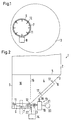
- the bottom of the silo container 3 has the same at its upper end Diameter like the jacket 2 of the silo container 1.
- Product that is in silo container 1 arrives therefore through the connection plane between the jacket 2 and the silo container bottom 3 into the interior 4 of the silo container bottom.
- the bottom of the silo container 3 has a discharge opening 6, which can be closed by a flap 7 is.
- the flap is in with solid lines closed position and with dashed lines in shown open position.
- the flap 7 has one only schematically illustrated drive 8, the it can pivot.
- the drive 8 would be in a top view in itself not visible.
- the discharge opening 6 is asymmetrical to the middle of the bottom of the silo container 3 arranged as shown in FIG. 1 is recognizable.
- the discharge opening 6 is arranged here that a section 9 of the wall 10 of the silo container bottom 3 vertically or at least almost vertically stands.
- FIGS. 1 and 2 are one Row of nozzles 11 directed into the discharge opening 6. Additional nozzles 12 are provided, which follow are directed above. These nozzles 11, 12 are from a Blower device 13 supplied. As detailed below will be explained, the blowing device 13 operates impulsive, i.e. emerge from the nozzles 11, 12 in short time intervals pressure surges of the gas, for example Compressed air, on. Instead of or in addition to these Nozzles can also nozzles not shown or be provided on the flap 7 by the Flap 7 are supplied through. Either way one also several or even all nozzles 11, 12 Combine slot-shaped ring nozzles.
- the nozzles 11, 12 are actuated as long as the flap 7 closed is.
- a control device 14 provided that both the blowing device 13 and controls the drive 8 for the flap 7. It ensures that at least at the beginning of the gas injection the interior 4 of the bottom of the silo container 3, the flap 7 is closed or remains.
- This is approximately cylindrical Room 16 is characterized by the vertical standing Section 9 of the wall 10 is limited. There can be one do not hold annular compressive stress in the product. Rather, the product slides down this wall and the ring tension in the product breaks down.
- Flap 7 is opened and the product through the discharge opening 6 can fall out after how before forming any ring stresses in the product because these collapse at section 9 of wall 10. The product is therefore usually completely out can be removed from the silo container 1.
- auxiliary blowing openings 17 can be provided be also from the blowing device 13 be operated.
- a valve 18 is provided via which the auxiliary blowing openings 17 are controlled can. Applying the auxiliary blowing openings Gas is usually only at the end of an emptying process required.
- the blowing device 13 has a pressure gas tank 19, that of a compressed gas source 20, for example one Compressor, supplied with compressed gas, such as air becomes.
- the compressed gas source 20 is a "normal" Line 21 connected to the pressure gas tank 19, i.e. with a line that has a common cross section. If the pressurized gas source 20 a certain distance from the pressure gas tank 10, then the line a certain, no longer negligible Flow resistance. As long as through the line 21 only a comparatively small amount of compressed gas flows, the flow losses are tolerable.
- the pressure gas tank 19 is connected via a line 22 to the Nozzles 11, 12 connected.
- Line 22 is short, i.e. the pressure gas tank 19 is in the immediate vicinity the discharge opening 6, and the line 22nd has a relatively large cross section.
- On the line 22 is a valve 23 arranged by the control device 14 is controlled. If the valve 23 is opened, then the compressed gas can escape from the tank 19 almost suddenly through line 22 to the nozzles 11, 12 discharge and so a pressure surge in the area 16 in the interior of the bottom of the silo 3 can. If the compressed gas tank 19 is discharged far enough, the valve 23 is closed again and the pressure gas tank 19 is being recharged.
- the control device 14 controls, as explained above, not only the valve 23, but also the drive 8 for the flap 7 in such a way that the flap 7 only is opened after the product in area 16 through fluidizes a predetermined number of pressure surges has been. If the flap 7 has been opened, then is a further fluidization of the product in the interior 4 of the bottom of the silo 3 not usually required, but the silo container 1 runs after once triggered, empty. Of course the idle can be interrupted by the Flap 7 is closed again.
Landscapes
- Engineering & Computer Science (AREA)
- Mechanical Engineering (AREA)
- Filling Or Emptying Of Bunkers, Hoppers, And Tanks (AREA)
- Storage Of Harvested Produce (AREA)
- Glass Compositions (AREA)
- Transition And Organic Metals Composition Catalysts For Addition Polymerization (AREA)
Applications Claiming Priority (2)
| Application Number | Priority Date | Filing Date | Title |
|---|---|---|---|
| DE10221964A DE10221964B4 (de) | 2002-05-17 | 2002-05-17 | Silobehälterboden |
| DE10221964 | 2002-05-17 |
Publications (3)
| Publication Number | Publication Date |
|---|---|
| EP1362802A2 true EP1362802A2 (fr) | 2003-11-19 |
| EP1362802A3 EP1362802A3 (fr) | 2004-01-21 |
| EP1362802B1 EP1362802B1 (fr) | 2005-11-23 |
Family
ID=29265336
Family Applications (1)
| Application Number | Title | Priority Date | Filing Date |
|---|---|---|---|
| EP03010152A Expired - Lifetime EP1362802B1 (fr) | 2002-05-17 | 2003-05-06 | Fond pour silos |
Country Status (3)
| Country | Link |
|---|---|
| EP (1) | EP1362802B1 (fr) |
| AT (1) | ATE310689T1 (fr) |
| DE (2) | DE10221964B4 (fr) |
Cited By (5)
| Publication number | Priority date | Publication date | Assignee | Title |
|---|---|---|---|---|
| US7640075B2 (en) | 2005-07-02 | 2009-12-29 | Syngenta Participations Ag | Apparatus and method for coordinating automated package and bulk dispensing |
| US8387824B2 (en) | 2005-07-02 | 2013-03-05 | Syngenta Participations Ag | Apparatuses and methods for bulk dispensing |
| EP2692666A1 (fr) * | 2012-08-02 | 2014-02-05 | Linde Aktiengesellschaft | Prévention des incendies dans des silos de stockage |
| CN109335357A (zh) * | 2018-12-06 | 2019-02-15 | 马钢集团矿业有限公司 | 一种矿料仓口疏通装置 |
| CN112960401A (zh) * | 2021-01-29 | 2021-06-15 | 江苏科瑞恩自动化科技有限公司 | 一种用于微型橡胶密封圈的自动上料机构 |
Families Citing this family (2)
| Publication number | Priority date | Publication date | Assignee | Title |
|---|---|---|---|---|
| DE102011002551A1 (de) | 2010-01-29 | 2011-08-04 | Feldbinder Spezialfahrzeugwerke GmbH, 21423 | Auslaufvorrichtung für Schüttgut |
| DE202010007631U1 (de) | 2010-01-29 | 2011-07-25 | Feldbinder Spezialfahrzeugwerke Gmbh | Auslaufvorrichtung für Schüttgut |
Citations (1)
| Publication number | Priority date | Publication date | Assignee | Title |
|---|---|---|---|---|
| DE19518360A1 (de) | 1995-05-19 | 1996-11-21 | Reimelt Dietrich Kg | Fließbett |
Family Cites Families (7)
| Publication number | Priority date | Publication date | Assignee | Title |
|---|---|---|---|---|
| DE714067C (de) * | 1938-06-08 | 1941-11-20 | Hannoversche Maschb Act Ges Vo | Vorratsbehaelterauslauftrichter fuer staubfoermiges Gut mit einer sich daran anschliessenden Entnahmefalleitung |
| US2569085A (en) * | 1944-08-17 | 1951-09-25 | Wood David Howard | Hopper, with valve closure having vibrator therein, for sand and other divided material |
| DE839330C (de) * | 1950-10-28 | 1952-05-19 | Natronzellstoff Und Papierfabr | Vorrichtung zum Abfuellen schwer fliessbarer Fuellgueter, vornehmlich fuer Sackfuellmaschinen mit automatischer Waage |
| DE1055447B (de) * | 1956-05-02 | 1959-04-16 | Friedrich Laas | Auflockerungseinrichtung an Behaeltern, Bunkern od. dgl. |
| US3578216A (en) * | 1968-12-03 | 1971-05-11 | William S Pearson | Prevention of arching compaction of discrete material in gravity feed hoppers |
| GB2092998A (en) * | 1981-02-13 | 1982-08-25 | Nat Res Dev | Handling materials of powder form |
| US5096096A (en) * | 1990-07-16 | 1992-03-17 | Thomas Conveyor Company | Fluidized bed discharge bin |
-
2002
- 2002-05-17 DE DE10221964A patent/DE10221964B4/de not_active Expired - Fee Related
-
2003
- 2003-05-06 EP EP03010152A patent/EP1362802B1/fr not_active Expired - Lifetime
- 2003-05-06 DE DE50301717T patent/DE50301717D1/de not_active Expired - Lifetime
- 2003-05-06 AT AT03010152T patent/ATE310689T1/de not_active IP Right Cessation
Patent Citations (1)
| Publication number | Priority date | Publication date | Assignee | Title |
|---|---|---|---|---|
| DE19518360A1 (de) | 1995-05-19 | 1996-11-21 | Reimelt Dietrich Kg | Fließbett |
Cited By (8)
| Publication number | Priority date | Publication date | Assignee | Title |
|---|---|---|---|---|
| US7640075B2 (en) | 2005-07-02 | 2009-12-29 | Syngenta Participations Ag | Apparatus and method for coordinating automated package and bulk dispensing |
| US8387824B2 (en) | 2005-07-02 | 2013-03-05 | Syngenta Participations Ag | Apparatuses and methods for bulk dispensing |
| US8442675B2 (en) | 2005-07-02 | 2013-05-14 | Syngenta Participations Ag | Apparatus and method for coordinating automated package and bulk dispensing |
| EP2692666A1 (fr) * | 2012-08-02 | 2014-02-05 | Linde Aktiengesellschaft | Prévention des incendies dans des silos de stockage |
| EP2756869A1 (fr) * | 2012-08-02 | 2014-07-23 | Linde Aktiengesellschaft | Prévention des incendies dans des silos de stockage |
| CN109335357A (zh) * | 2018-12-06 | 2019-02-15 | 马钢集团矿业有限公司 | 一种矿料仓口疏通装置 |
| CN109335357B (zh) * | 2018-12-06 | 2023-08-15 | 马钢集团矿业有限公司 | 一种矿料仓口疏通装置 |
| CN112960401A (zh) * | 2021-01-29 | 2021-06-15 | 江苏科瑞恩自动化科技有限公司 | 一种用于微型橡胶密封圈的自动上料机构 |
Also Published As
| Publication number | Publication date |
|---|---|
| EP1362802B1 (fr) | 2005-11-23 |
| ATE310689T1 (de) | 2005-12-15 |
| EP1362802A3 (fr) | 2004-01-21 |
| DE50301717D1 (de) | 2005-12-29 |
| DE10221964B4 (de) | 2005-11-10 |
| DE10221964A1 (de) | 2003-11-27 |
Similar Documents
| Publication | Publication Date | Title |
|---|---|---|
| EP0513582B1 (fr) | Système et méthode de transport du matériel granulaire | |
| EP3212306B1 (fr) | Procédé de nettoyage et dispositif de commande | |
| EP1232003A2 (fr) | Dispositif de revetement de particules | |
| DE3145017A1 (de) | Pneumatische foerderanlage | |
| DE1425851A1 (de) | Geraet zum Verspruehen von Fluessigkeiten | |
| DE10231813A1 (de) | Dosieranlage für Pulverpigmente | |
| DE3310452A1 (de) | Verfahren und vorrichtung zur automatischen pneumatischen beschickung einer vielzahl von verbrauchsstellen mit pulverfoermigem gut | |
| EP1362802B1 (fr) | Fond pour silos | |
| DE2821517C2 (de) | Pneumatische Förderanlage für pulverförmiges Gut | |
| WO2016074797A1 (fr) | Procédé permettant d'équilibrer la pression gazeuse dans une trémie d'écoulement massique | |
| EP1000889B1 (fr) | Dispositif pour transférer des produits fluides | |
| EP2241867B1 (fr) | Dispositif et agencement destinés au remplissage de postes de traitement | |
| DE7611781U1 (de) | Vorrichtung zum austreiben von schuettgut aus einem innendruckbelastbaren silobehaelter | |
| EP0499102A1 (fr) | Cône de déchargement d'un récipient, par exemple d'un silo | |
| DE2623705A1 (de) | Austragvorrichtung fuer schuettgueter | |
| DE1087526B (de) | Vorrichtung zum Erleichtern der Entnahme oder der Zufuhr von Schuettgut und/oder zum Auflockern von Schuettgut an einem Transport- oder Lagersilo | |
| DE69607354T2 (de) | Ventil zur durchflussregelung eines fluids, welches fette teilchen enthält | |
| EP0247235B1 (fr) | Dispositif de transport d'air comprimé et dispositif doseur | |
| DE3810191C2 (fr) | ||
| DE2139465A1 (de) | Vorrichtung und verfahren zur behandlung von teilchen in einem schwebeteilchenbett mit hilfe eines gasstromes | |
| EP1693316A1 (fr) | Dispositif de sortie avec un système de nettoyage | |
| DE202005002563U1 (de) | Auslaufeinrichtung | |
| DE3042414A1 (de) | Vorrichtung zur wiedererregung des flusses in schuettgutsilos | |
| DE20104330U1 (de) | Entleereinrichtung für einen Schüttgut-Container | |
| DE1102650B (de) | Pneumatischer Foerderer zum Foerdern von Massenguetern mittels Druckluft aus einem Behaelter in eine Rohrleitung |
Legal Events
| Date | Code | Title | Description |
|---|---|---|---|
| PUAI | Public reference made under article 153(3) epc to a published international application that has entered the european phase |
Free format text: ORIGINAL CODE: 0009012 |
|
| AK | Designated contracting states |
Kind code of ref document: A2 Designated state(s): AT BE BG CH CY CZ DE DK EE ES FI FR GB GR HU IE IT LI LU MC NL PT RO SE SI SK TR |
|
| AX | Request for extension of the european patent |
Extension state: AL LT LV MK |
|
| PUAL | Search report despatched |
Free format text: ORIGINAL CODE: 0009013 |
|
| AK | Designated contracting states |
Kind code of ref document: A3 Designated state(s): AT BE BG CH CY CZ DE DK EE ES FI FR GB GR HU IE IT LI LU MC NL PT RO SE SI SK TR |
|
| AX | Request for extension of the european patent |
Extension state: AL LT LV MK |
|
| RIC1 | Information provided on ipc code assigned before grant |
Ipc: 7B 65D 88/72 A Ipc: 7B 65D 88/28 B Ipc: 7B 65D 88/70 B Ipc: 7B 65D 90/58 B |
|
| 17P | Request for examination filed |
Effective date: 20031219 |
|
| 17Q | First examination report despatched |
Effective date: 20040407 |
|
| AKX | Designation fees paid |
Designated state(s): AT BE BG CH CY CZ DE DK EE ES FI FR GB GR HU IE IT LI LU MC NL PT RO SE SI SK TR |
|
| GRAP | Despatch of communication of intention to grant a patent |
Free format text: ORIGINAL CODE: EPIDOSNIGR1 |
|
| GRAS | Grant fee paid |
Free format text: ORIGINAL CODE: EPIDOSNIGR3 |
|
| GRAA | (expected) grant |
Free format text: ORIGINAL CODE: 0009210 |
|
| AK | Designated contracting states |
Kind code of ref document: B1 Designated state(s): AT BE BG CH CY CZ DE DK EE ES FI FR GB GR HU IE IT LI LU MC NL PT RO SE SI SK TR |
|
| PG25 | Lapsed in a contracting state [announced via postgrant information from national office to epo] |
Ref country code: IT Free format text: LAPSE BECAUSE OF FAILURE TO SUBMIT A TRANSLATION OF THE DESCRIPTION OR TO PAY THE FEE WITHIN THE PRESCRIBED TIME-LIMIT;WARNING: LAPSES OF ITALIAN PATENTS WITH EFFECTIVE DATE BEFORE 2007 MAY HAVE OCCURRED AT ANY TIME BEFORE 2007. THE CORRECT EFFECTIVE DATE MAY BE DIFFERENT FROM THE ONE RECORDED. Effective date: 20051123 Ref country code: CZ Free format text: LAPSE BECAUSE OF FAILURE TO SUBMIT A TRANSLATION OF THE DESCRIPTION OR TO PAY THE FEE WITHIN THE PRESCRIBED TIME-LIMIT Effective date: 20051123 Ref country code: FI Free format text: LAPSE BECAUSE OF FAILURE TO SUBMIT A TRANSLATION OF THE DESCRIPTION OR TO PAY THE FEE WITHIN THE PRESCRIBED TIME-LIMIT Effective date: 20051123 Ref country code: IE Free format text: LAPSE BECAUSE OF FAILURE TO SUBMIT A TRANSLATION OF THE DESCRIPTION OR TO PAY THE FEE WITHIN THE PRESCRIBED TIME-LIMIT Effective date: 20051123 Ref country code: SK Free format text: LAPSE BECAUSE OF FAILURE TO SUBMIT A TRANSLATION OF THE DESCRIPTION OR TO PAY THE FEE WITHIN THE PRESCRIBED TIME-LIMIT Effective date: 20051123 Ref country code: NL Free format text: LAPSE BECAUSE OF FAILURE TO SUBMIT A TRANSLATION OF THE DESCRIPTION OR TO PAY THE FEE WITHIN THE PRESCRIBED TIME-LIMIT Effective date: 20051123 Ref country code: RO Free format text: LAPSE BECAUSE OF FAILURE TO SUBMIT A TRANSLATION OF THE DESCRIPTION OR TO PAY THE FEE WITHIN THE PRESCRIBED TIME-LIMIT Effective date: 20051123 Ref country code: SI Free format text: LAPSE BECAUSE OF FAILURE TO SUBMIT A TRANSLATION OF THE DESCRIPTION OR TO PAY THE FEE WITHIN THE PRESCRIBED TIME-LIMIT Effective date: 20051123 |
|
| REG | Reference to a national code |
Ref country code: GB Ref legal event code: FG4D Free format text: NOT ENGLISH |
|
| REG | Reference to a national code |
Ref country code: CH Ref legal event code: EP |
|
| REF | Corresponds to: |
Ref document number: 50301717 Country of ref document: DE Date of ref document: 20051229 Kind code of ref document: P |
|
| REG | Reference to a national code |
Ref country code: IE Ref legal event code: FG4D Free format text: LANGUAGE OF EP DOCUMENT: GERMAN |
|
| GBT | Gb: translation of ep patent filed (gb section 77(6)(a)/1977) |
Effective date: 20051219 |
|
| PG25 | Lapsed in a contracting state [announced via postgrant information from national office to epo] |
Ref country code: GR Free format text: LAPSE BECAUSE OF FAILURE TO SUBMIT A TRANSLATION OF THE DESCRIPTION OR TO PAY THE FEE WITHIN THE PRESCRIBED TIME-LIMIT Effective date: 20060223 Ref country code: DK Free format text: LAPSE BECAUSE OF FAILURE TO SUBMIT A TRANSLATION OF THE DESCRIPTION OR TO PAY THE FEE WITHIN THE PRESCRIBED TIME-LIMIT Effective date: 20060223 Ref country code: SE Free format text: LAPSE BECAUSE OF FAILURE TO SUBMIT A TRANSLATION OF THE DESCRIPTION OR TO PAY THE FEE WITHIN THE PRESCRIBED TIME-LIMIT Effective date: 20060223 Ref country code: BG Free format text: LAPSE BECAUSE OF FAILURE TO SUBMIT A TRANSLATION OF THE DESCRIPTION OR TO PAY THE FEE WITHIN THE PRESCRIBED TIME-LIMIT Effective date: 20060223 |
|
| PG25 | Lapsed in a contracting state [announced via postgrant information from national office to epo] |
Ref country code: ES Free format text: LAPSE BECAUSE OF FAILURE TO SUBMIT A TRANSLATION OF THE DESCRIPTION OR TO PAY THE FEE WITHIN THE PRESCRIBED TIME-LIMIT Effective date: 20060306 |
|
| PG25 | Lapsed in a contracting state [announced via postgrant information from national office to epo] |
Ref country code: PT Free format text: LAPSE BECAUSE OF FAILURE TO SUBMIT A TRANSLATION OF THE DESCRIPTION OR TO PAY THE FEE WITHIN THE PRESCRIBED TIME-LIMIT Effective date: 20060424 |
|
| NLV1 | Nl: lapsed or annulled due to failure to fulfill the requirements of art. 29p and 29m of the patents act | ||
| PG25 | Lapsed in a contracting state [announced via postgrant information from national office to epo] |
Ref country code: AT Free format text: LAPSE BECAUSE OF NON-PAYMENT OF DUE FEES Effective date: 20060506 |
|
| PG25 | Lapsed in a contracting state [announced via postgrant information from national office to epo] |
Ref country code: HU Free format text: LAPSE BECAUSE OF FAILURE TO SUBMIT A TRANSLATION OF THE DESCRIPTION OR TO PAY THE FEE WITHIN THE PRESCRIBED TIME-LIMIT Effective date: 20060524 |
|
| PG25 | Lapsed in a contracting state [announced via postgrant information from national office to epo] |
Ref country code: MC Free format text: LAPSE BECAUSE OF NON-PAYMENT OF DUE FEES Effective date: 20060531 Ref country code: BE Free format text: LAPSE BECAUSE OF NON-PAYMENT OF DUE FEES Effective date: 20060531 |
|
| REG | Reference to a national code |
Ref country code: IE Ref legal event code: FD4D |
|
| ET | Fr: translation filed | ||
| PLBE | No opposition filed within time limit |
Free format text: ORIGINAL CODE: 0009261 |
|
| STAA | Information on the status of an ep patent application or granted ep patent |
Free format text: STATUS: NO OPPOSITION FILED WITHIN TIME LIMIT |
|
| 26N | No opposition filed |
Effective date: 20060824 |
|
| REG | Reference to a national code |
Ref country code: FR Ref legal event code: ST Effective date: 20070131 |
|
| BERE | Be: lapsed |
Owner name: REIMELT G.M.B.H. Effective date: 20060531 |
|
| REG | Reference to a national code |
Ref country code: CH Ref legal event code: PL |
|
| GBPC | Gb: european patent ceased through non-payment of renewal fee |
Effective date: 20070506 |
|
| PG25 | Lapsed in a contracting state [announced via postgrant information from national office to epo] |
Ref country code: CH Free format text: LAPSE BECAUSE OF NON-PAYMENT OF DUE FEES Effective date: 20070531 Ref country code: LI Free format text: LAPSE BECAUSE OF NON-PAYMENT OF DUE FEES Effective date: 20070531 |
|
| PG25 | Lapsed in a contracting state [announced via postgrant information from national office to epo] |
Ref country code: FR Free format text: LAPSE BECAUSE OF NON-PAYMENT OF DUE FEES Effective date: 20060531 |
|
| PG25 | Lapsed in a contracting state [announced via postgrant information from national office to epo] |
Ref country code: GB Free format text: LAPSE BECAUSE OF NON-PAYMENT OF DUE FEES Effective date: 20070506 |
|
| PG25 | Lapsed in a contracting state [announced via postgrant information from national office to epo] |
Ref country code: EE Free format text: LAPSE BECAUSE OF FAILURE TO SUBMIT A TRANSLATION OF THE DESCRIPTION OR TO PAY THE FEE WITHIN THE PRESCRIBED TIME-LIMIT Effective date: 20051123 |
|
| PG25 | Lapsed in a contracting state [announced via postgrant information from national office to epo] |
Ref country code: TR Free format text: LAPSE BECAUSE OF FAILURE TO SUBMIT A TRANSLATION OF THE DESCRIPTION OR TO PAY THE FEE WITHIN THE PRESCRIBED TIME-LIMIT Effective date: 20051123 Ref country code: LU Free format text: LAPSE BECAUSE OF NON-PAYMENT OF DUE FEES Effective date: 20060506 |
|
| PG25 | Lapsed in a contracting state [announced via postgrant information from national office to epo] |
Ref country code: CY Free format text: LAPSE BECAUSE OF FAILURE TO SUBMIT A TRANSLATION OF THE DESCRIPTION OR TO PAY THE FEE WITHIN THE PRESCRIBED TIME-LIMIT Effective date: 20051123 |
|
| REG | Reference to a national code |
Ref country code: DE Ref legal event code: R081 Ref document number: 50301717 Country of ref document: DE Owner name: ZEPPELIN SYSTEMS GMBH, DE Free format text: FORMER OWNER: REIMELT GMBH, 63322 ROEDERMARK, DE Effective date: 20140703 Ref country code: DE Ref legal event code: R082 Ref document number: 50301717 Country of ref document: DE Representative=s name: PATENTANWAELTE KNOBLAUCH UND KNOBLAUCH, DE Effective date: 20140703 |
|
| REG | Reference to a national code |
Ref country code: DE Ref legal event code: R082 Ref document number: 50301717 Country of ref document: DE Representative=s name: KEIL & SCHAAFHAUSEN PATENTANWAELTE PARTGMBB, DE Ref country code: DE Ref legal event code: R082 Ref document number: 50301717 Country of ref document: DE Representative=s name: KEIL & SCHAAFHAUSEN PATENT- UND RECHTSANWAELTE, DE |
|
| PGFP | Annual fee paid to national office [announced via postgrant information from national office to epo] |
Ref country code: DE Payment date: 20220525 Year of fee payment: 20 |
|
| REG | Reference to a national code |
Ref country code: DE Ref legal event code: R071 Ref document number: 50301717 Country of ref document: DE |