EP1362977B1 - Tube de production avec câblage électrique dans un revêtement de conduite tubulaire - Google Patents
Tube de production avec câblage électrique dans un revêtement de conduite tubulaire Download PDFInfo
- Publication number
- EP1362977B1 EP1362977B1 EP03252856A EP03252856A EP1362977B1 EP 1362977 B1 EP1362977 B1 EP 1362977B1 EP 03252856 A EP03252856 A EP 03252856A EP 03252856 A EP03252856 A EP 03252856A EP 1362977 B1 EP1362977 B1 EP 1362977B1
- Authority
- EP
- European Patent Office
- Prior art keywords
- tubing
- wire
- insert
- cylindrical insert
- coupler
- Prior art date
- Legal status (The legal status is an assumption and is not a legal conclusion. Google has not performed a legal analysis and makes no representation as to the accuracy of the status listed.)
- Expired - Lifetime
Links
Images




Classifications
-
- E—FIXED CONSTRUCTIONS
- E21—EARTH OR ROCK DRILLING; MINING
- E21B—EARTH OR ROCK DRILLING; OBTAINING OIL, GAS, WATER, SOLUBLE OR MELTABLE MATERIALS OR A SLURRY OF MINERALS FROM WELLS
- E21B17/00—Drilling rods or pipes; Flexible drill strings; Kellies; Drill collars; Sucker rods; Cables; Casings; Tubings
- E21B17/003—Drilling rods or pipes; Flexible drill strings; Kellies; Drill collars; Sucker rods; Cables; Casings; Tubings with electrically conducting or insulating means
Definitions
- the present invention generally relates to tubing that is used to produce hydrocarbons in a subterranean environment and more specifically to tubing having electrical wiring.
- the currently preferred method of power transmission to the bottom of the well bore is to secure a cable, that contains one or more wires by means of bands that secure the cable to the outside of the production string of tubing.
- the bands keep the wire adjacent to the tubing so that it does not snag on the production casing or on any objects which might be in the well bore.
- the bands also support the weight of the cable by securing the cable to the tubing.
- this method is problematic because it exposes the cable and bands to the corrosive elements of the well bore.
- the tubing string then has to be pulled back up to the surface, and the short found and repaired, before the pump can be run back to bottom of the well bore.
- the problems created by banded external cables are costly and time consuming. Therefore, a need exists for an alternative method of power transmission from the surface to the bottom of the well bore that is both reliable and cost effective.
- One solution to the above stated problem is to employ a plurality of tubing with multiple wires attached to the inside of the tubing instead of the outside of the drill pipe. While this solution alleviates the problem of snagging the wire, it does not solve the problem of exposing the wire to the harsh environment of the produced fluids that are contained within the production tubing. Simply hanging the cable on the inside of the tubing is also problematic because there is no way to support the weight of the cable and the pressure requirements of the pump will be higher due to the added friction between the fluid that is being pumped and the rough exterior of the cable.
- the multiple conduits create weak points in the drill pipe in between the conduits.
- the high rotational stress which the drill pipe encounters in the drilling operations can cause stress fractures in the pipe wall between the multiple conduit tubulars.
- high rotational stress can lead to an internal fracture in the drill pipe that disengages the interior wall of the drill pipe from the exterior wall of the drill pipe.
- the manufacture of the multiple conduit drill pipe is a complicated process which is unlike the manufacturing process for conventional drill pipe.
- Conventional drill pipe is manufactured by attaching male and female pipe connections to opposite ends of a conventional piece of pipe. The two connections are usually welded to the pipe.
- Multiple conduit pipes must be either extruded with the multiple conduits in place, or the multiple conduits must be drilled or cut out of a conventional drill pipe. In either case, the costs associated with manufacture of multiple conduit drill pipe are high.
- US-A-4,496,203 discloses a drill pipe section comprising a generally cylindrical housing member and a liner member fixedly mounted inside the housing member with an air gap defined between the two members.
- An electrically conductive element extends between two annular coupling components, one of which defines a radially inward directed coupling margin and the other of which defines a radially outward directed coupling margin.
- tubing shall mean production tubing, drill pipe, casing, and/or any other cylindrical pipe that is used to produce hydrocarbons in a subterranean environment.
- the present invention concerns an improved tubing which addresses the problems presented by earlier inventions involving tubing and electrical wiring combinations.
- the invention comprises a section of tubing with coupled end connectors and an insert containing at least one electrical wire.
- the insert has an outside diameter that is approximately equal to the inside diameter of the improved tubing.
- the insert also has projections at each end such that when two inserts are placed end to end, the projections will mate up.
- the insert has at least one groove cut into its side and running the length of the insert. The groove is for the placement of a wire for transmission of power to the well bore or for the placement of a wire for transmission of data from the well bore. The groove is installed down the length of the insert.
- the groove is deep enough so that when a wire is placed inside the groove, the wire does not project beyond the outside diameter of the insert.
- the insert may contain as many groove and wire combinations as are necessary for the particular application.
- the wire has an electrical connection at each end of the insert. When the inserts are placed end to end, the insert projections line up the electrical connectors and correct mating of the insert projections will result in correct mating of the electrical connectors.
- the inserts are the same length as the tubing and are installed inside the tubing such that the insert is flush with the first end of the tubing.
- the inserts are then welded to the tubing or secured to the tubing by some other method.
- a threaded coupler is then installed on the second end of the tubing to protect the exposed insert and electrical connector. The coupler will also be used to secure the improved tubing together.
- Improved tubing means tubing that is adapted to receive a coupler and that has an insert.
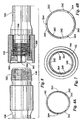
- Figure 1 is an illustration of improved tubing 100 without insert 200 (see Fig. 2) or coupler 300 (see Fig. 5).
- Improved tubing 100 is comprised of three sections: first end 120, midsection 140, and second end 160.
- First end 120 comprises coarse threads 122, first end weld joint 124, and wrench grip 126.
- Midsection 140 comprises pipe 142, pipe first end 144, and pipe second end 146.
- Second end 160 comprises fine threads 162, second end weld joint 164, and coupler stop flange 166.
- First end 120 and second end 160 may be like those found in U.S.
- first end 120 and second end 160 are manufactured by either casting or forging and pipe 142 is manufactured by some other method (i.e. electric resistance welding or extrusion).
- the manufacture of improved tubing 100 involves the threading of first end 120 and second end 160 to pipe 142. While the preferred method of manufacturing first end 120 and second end 160 is threading the two ends of improved tubing 100, those skilled in the art will be aware of other methods of manufacturing first end 120 and second end 160. Regardless of the method of manufacture, the inside diameter of first end 120, midsection 140, and second end 160 are substantially the same so that when insert 200 engages improved tubing 100, the outside surface area of insert 200 contacts the inside surface area of improved tubing 100.
- Insert 200 is comprised of insert first end 220, insert midsection 240, and insert second end 260.
- Insert first end 220 comprises insert first end projection 222 and insert first end electrical connection 224.
- Insert midsection 240 comprises insert body 242 and insert groove 244.
- Insert second end 260 comprises insert second end projection 262 and insert second end electrical connection 264.
- the depressions in insert second end 260 in between insert second end projections 262 match up with the insert first end projections 222.
- the depressions in insert first end 220 in between insert first end projections 222 match up with the insert second end projections 262.
- Insert 200 also contains insert groove 244 which is a groove cut down the long axis of insert 200. Insert groove 244 is sufficiently large to accommodate at least one wire 246. Wire 246 is electrically coupled to insert first end electrical connection 224 and insert second end electrical connection 264 and is used as a medium to transfer electricity from the surface to the bottom of the well bore. Insert first end electrical connection 224 and insert first end electrical connection 264 are single plug connectors similar to the K-25 series electrical connectors produced by Kemlon Products and Development Co. of Pearland, Texas. The K-25 series of single plug electrical connections are able to withstand temperatures up to 260°C (500°F) and pressures up to 172MPa (25,000 psi).
- Figure 4A is a cross-section of the two wire embodiment of insert 200 taken along line 4-4 in figure 2.
- Inset 200 may contain only one wire 246 or may contain a plurality of wires 246.
- figures 1 through 9B depict the invention with only two wires.
- wire 246 can be a fiber optic in which case the two electrical connections on insert 200 would be optical connections and the fiber optic would be optically coupled to the optical connections.
- the invention could employ a mixture of fiber optics and electrical wires.
- the invention incorporates three wires such that the three wires each carry the appropriate load of a three phase, 440-volt electrical system, as illustrated in figures 4B and 10 through 15.
- the number and type of wires is not meant to be a limitation on the invention as those skilled in the art will be aware of how best to configure the invention with fiber optics, electrical wiring, or other connections within insert groove 244 of improved drill pipe 100.
- FIG 3 is an illustration of improved tubing 100 with insert 200 installed.
- Insert 200 is sized lengthwise so that when insert 200 is inserted into improved tubing 100, insert first end projection 222 is flush with first end 120 and insert second end projection 262 is the only portion of insert 200 that is projecting beyond second end 160.
- insert 200 is circumferentially sized such that the outer diameter of insert 200 is sufficiently equal to the inside diameter of improved tubing 100.
- Insert groove 244 is sufficiently deep in insert body 242 so that wire 246 does not extend beyond the outer diameter of insert 200, yet is not deep enough to affect the structural integrity of insert 200.
- Insert 200 is coaxially positioned inside improved tubing 100 and secured in place.
- insert 200 is the same material as improved tubing 100 and is secured in place by welding.
- insert 200 can be made of any material suitable for drilling operations including various metal alloys, fiberglass, plastic PVC, polymer, or any other material as determined by those of skill in the art.
- insert 200 can be secured in place by welding, glue, heat shrinking, expanding, set screws, or any other method as determined by those skilled in the art.
- Heat shrinking is defined as a process in which the outer pipe is heated so that the outer pipe expands, the insert is positioned inside the pipe, and the pipe is allowed to cool so that it contracts and secures the insert in place.
- Expanding is a process in which a tool (expander), having a slightly larger outside diameter than the inside diameter of the insert, is pulled forcibly through the insert causing the outside surface of the insert to expand and grip the inside of the improved tubing.
- Set screws is a process in which the improved tubing and insert are tapped and threaded and a screw is inserted through the improved tubing and insert to secure the insert in place relative to the pipe.
- Figure 5 is an exploded illustration of the connection between two separate pieces of improved tubing 100 with insert 200 installed and coupler 300 positioned for installation on first end 120 and drill pipe second end 160.
- Coupler 300 is annular in shape and contains coupler fine threads 302 and coupler coarse threads 304. Coupler fine threads 302 are configured for screwing engagement with drill pipe fine threads 162. Coupler coarse threads 304 are configured for screwing engagement with drill pipe coarse threads 122. The pitch of drill pipe coarse threads 122 and drill pipe fine threads 162 are different pitch so that coupler 300 can only mate up with improved tubing 100 in one orientation.
- coupler stop flange 166 has a larger cross-sectional area than fine threads 162 and acts as a stop for coupler 300 so that coupler 300 does not go past second end 160.
- the outside diameter of coupler 300 is sufficiently similar to pipe wrench grip 126 so that when the user is attaching the individual pieces of improved drill pipe 100 together, a pipe wrench will fit onto both pipe wrench grip 126 and coupler 300 without undue adjustment of the pipe wrench.
- Coarse threads 122 and coupler coarse threads 304 are tapered so that they may be completely engaged with a minimal amount of rotations after first end 120 and second end 160 have been plugged together.
- Coupler 300 is also sufficiently long so that when coupler 300 is completely screwed onto second end 160 and abuts coupler stop flange 166, coupler 300 extends past insert second end projection 262. It is advantageous that coupler 300 extend past insert second end projection 262 because improved tubing 100 will typically be stored, transported, and handled with coupler 300 installed on second end 160 and coupler 300 will protect insert second end 260 and specifically insert second end electrical connection 264 from damage.
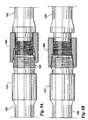
- Figure 8 is an illustration of coupler 300 installed on second end 160 just prior to connection of two pieces of improved tubing 100.
- Figure 8 is representative of how improved tubing 100 will be stored, transported, and handled.
- coupler 300 extends past insert second end projection 262 and insert second end electrical connection 264.
- FIGs 8, 9A, and 9B illustrate the process of attaching two sections of improved tubing 100 together.
- the improved tubing 100 may also be connected in the horizontal. However, the preferred embodiment and industry standard is to place the second end 160 above the first end 120.
- the attachment process comprises four steps: positioning, aligning, plugging, and securing.
- the two sections of improved tubing 100 are positioned over one another with a second end 160 of one improved tubing 100 facing the first end 120 of the other improved tubing 100.
- the aligning step consists of rotating one or both sections of improved tubing 100 such that the insert second end projection 262 in one section of improved tubing 100 will properly mate with the insert first end projection 222 in the other section of improved tubing 100.
- FIG 9A is an illustration of the plugging step in which two sections of improved tubing 100 are plugged together.
- the plugging step the second end 160 of one section of improved tubing 100 is lowered onto the first end 120 of the other section of improved tubing 100 until the two sections of improved tubing 100 contact each other and/or the two inserts 200 fully mate with each other.
- insert second end projections 262 will fill the depression between insert first end projections 222 and insert first end projections 222 will fill the depression between insert second end projections 262.
- insert first end electrical connection 224 and insert second end electrical connection 264 will electrically couple and provide an electrical connection which will tolerate the harsh environment of the well bore. After the two improved tubing 100 are plugged together, they are secured by screwing coupler 300 onto first end 120.
- Figure 9B is an illustration of two sections of improved tubing 100 secured together by coupler 300.
- Coupler 300 is secured to first end 120 by pipe wrenches (not shown) which grip coupler 300 and pipe wrench grip 126 and torque coupler 300 until coupler 300 is firmly screwed onto drill pipe first end 120.
- the two sections of improved tubings 100 may then be used in the production process.
- Figures 10 through 14 illustrate a three wire embodiment.
- the manufacture of the three wire improved drill pipe is similar to the manufacture of the two wire improved tubing.
- the assembly of a plurality of three wire improved tubing is similar to the assembly of a plurality of two wire improved tubing.
- Figure 10 is an illustration of the alignment step for a three wire embodiment of the insert in which coupler 300 is installed on second end 160.
- the dashed line in figure 10 indicates the alignment of insert first end electrical connection 224 and insert second end electrical connection 264.
- insert first end projection 222 and insert second end projection 262 are also properly aligned.
- Figure 11 is a cross-sectional illustration of the three wire embodiment of insert 200 and improved tubing 100 taken along line 11-11 in figure 10.
- Figure 12 is an illustration of the plugging step for the three wire embodiment of insert 200 taken along line 11-11 in figure 10.
- Figure 13 is an illustration of the securing step of two pieces of improved tubing 100 with the three wire embodiment of insert 200 and the coupler disengaged from the first end of the tubing.
- Figure 14 is a cross-section of the three wire embodiment of the insert taken along line 14-14 in figure 13.
- Insert 200 in the three wire embodiment is similar to insert 200 in the two wire embodiment in that the inside diameter of pipe 142 is substantially the same as the outside diameter of inset body 242.
- Figure 15 is a detail view of the geometry between insert 200, wire 246, and improved tubing 100 around the area indicated by circle 15 in figure 14.
- Figure 15 illustrates the point that insert groove 244 is cut into insert body 242 so that wire 246 does not project above the outer surface of insert body 242.
- Figure 16 is an illustration of a submerged pump in a production situation.
- Figure 16 shows multiple pieces of improved tubing 100 with the inserts installed (not shown). Power comes from an external source 402 and is stepped down in transformer 404, is routed through vent box 406, and goes to wellhead 408. Power is transmitted down tubing pump 412 and or motor 414. Well bore 418 is typically cased with casing 416.
- the present invention has been described in relation to an improved tubing.
- the invention also extends to the constituent parts thereof when manufactured or supplied separately.
- the invention also extends to the insert and the coupler as described herein.
Landscapes
- Engineering & Computer Science (AREA)
- Life Sciences & Earth Sciences (AREA)
- Geology (AREA)
- Mining & Mineral Resources (AREA)
- Mechanical Engineering (AREA)
- Physics & Mathematics (AREA)
- Environmental & Geological Engineering (AREA)
- Fluid Mechanics (AREA)
- General Life Sciences & Earth Sciences (AREA)
- Geochemistry & Mineralogy (AREA)
- Connector Housings Or Holding Contact Members (AREA)
- Electric Cable Installation (AREA)
- Earth Drilling (AREA)
- Mechanical Coupling Of Light Guides (AREA)
- Connections Effected By Soldering, Adhesion, Or Permanent Deformation (AREA)
- Laying Of Electric Cables Or Lines Outside (AREA)
- Manufacturing Of Electric Cables (AREA)
- Communication Cables (AREA)
- Installation Of Indoor Wiring (AREA)
- Details Of Connecting Devices For Male And Female Coupling (AREA)
Claims (25)
- Appareil pour former un tube de production ayant une capacité de transmission le long d'au moins un câble, comprenant :une garniture intérieure cylindrique (200) adaptée pour être mise en prise en cours d'utilisation avec l'intérieur d'un tube de production (100) ; etau moins une rainure (244) disposée dans le sens de la longueur dans ladite garniture intérieure cylindrique (200), le ou les câbles (246) étant positionnés à l'intérieur de ladite rainure (244) ;caractérisé par :au moins une saillie (222) sur une première extrémité (220) de ladite garniture intérieure cylindrique (200) et au moins un enfoncement sur une seconde extrémité (260) de ladite garniture intérieure cylindrique (200) ; etétant précisé qu'en cours d'utilisation, la ou les saillies (222) sur un premier tube de production (100) s'accouplent avec le ou les enfoncements sur un second tube de production (100) pour coupler le ou les câbles (246) entre chaque premier et second tubes de production (100) lorsqu'une pluralité desdits tubes de production (100) comportant lesdites garnitures intérieures (200) sont alignés le long d'un axe commun.
- Appareil selon la revendication 1, comprenant en outre :un tube de production (100) ayant une première extrémité (120) et une seconde extrémité (160), et ayant un intérieur et un extérieur ;la garniture intérieure cylindrique (200) étant mise en prise avec l'intérieur du tube de production (100).
- Appareil selon la revendication 1 ou 2, dans lequel la ou les rainures (244) sont réalisées sur l'extérieur de ladite garniture intérieure (200).
- Appareil selon la revendication 1, 2 ou 3, comprenant en outre une paire de raccords (224, 264) couplée à au moins un câble (246), un raccord (224) étant prévu au niveau de la première extrémité (220) de ladite garniture intérieure cylindrique (200) et un raccord (264) étant prévu au niveau de la seconde extrémité (260) de ladite garniture intérieure cylindrique (200).
- Appareil selon la revendication 4, dans lequel lesdits raccords (224, 264) sont couplés lorsque ladite saillie (222) s'accouple avec ledit enfoncement.
- Appareil selon la revendication 5, dans lequel lesdits raccords (224, 264) sont des raccords électriques, ledit couplage est un couplage électrique et ledit câble (246) est un câble électrique.
- Appareil selon la revendication 5, dans lequel lesdits raccords (224, 264) sont des raccords optiques, ledit couplage est un couplage optique et ledit câble (246) est une fibre optique.
- Appareil selon la revendication 2 ou selon l'une quelconque des revendications précédentes indépendantes, comprenant en outre un coupleur (300) mis en prise en rotation sur la seconde extrémité (160) dudit premier tube de production (100) et mis en prise en rotation sur la première extrémité (120) dudit second tube de production (100) afin de fixer la liaison entre les premier et second tubes de production (100).
- Appareil selon la revendication 8, comprenant en outre une collerette de butée (166) pour coupleur disposée au niveau de la seconde extrémité (160) dudit tube de production (100) de sorte que le coupleur (300) s'étend au-delà de la seconde extrémité (260) de la garniture intérieure cylindrique.
- Appareil selon la revendication 8 ou 9, dans lequel le coupleur (300) est mis en prise en rotation avec la seconde extrémité (160) du premier tube de production (100) au moyen de filetages fins (302), et présente en outre des filetages gros (304) destinés à mettre en prise la première extrémité (120) du second tube de production (100).
- Appareil selon la revendication 10, dans lequel lesdits filetages gros (304) sont des filetages coniques.
- Appareil selon l'une quelconque des revendications précédentes, dans lequel le tube de production (100) est utilisé dans un forage de puits pour l'extraction de fluides d'un environnement souterrain.
- Procédé de fixation d'un premier tube de production (100) sur un second tube de production (100), chaque tube de production (100) comportant une garniture intérieure cylindrique coaxiale (200), une rainure longitudinale (244) réalisée sur l'extérieur de ladite garniture intérieure (200) et au moins un câble (246) positionné à l'intérieur de ladite rainure (244), le procédé comprenant les étapes consistant à :positionner ledit premier tube de production (100) coaxialement par rapport audit second tube de production (100) ;coupler une première extrémité du ou des câbles (246) dans le second tube de production (100) avec une seconde extrémité du ou des câbles (246) dans le premier tube de production (100) pour fournir une capacité de transmission le long de celui-ci ; etfixer ledit premier tube de production (100) audit second tube de production (100) ;caractérisé en ce qu'il comprend l'étape consistant à :aligner au moins une saillie (222) qui s'étend depuis une première extrémité (220) de ladite garniture intérieure cylindrique (200) sur ledit second tube de production (100) avec au moins un enfoncement sur une seconde extrémité (260) de ladite garniture intérieure cylindrique (200) dudit premier tube de production (100).
- Procédé selon la revendication 13, dans lequel ledit second tube de production (100) est positionné verticalement au-dessus dudit premier tube de production (100).
- Procédé selon la revendication 13 ou 14, comprenant en outre l'étape consistant à connecter électriquement la première extrémité du ou des câbles (246) dans le premier tube de production (100) à la seconde extrémité du ou des câbles (246) dans le second tube de production (100).
- Procédé selon la revendication 13 ou 14, comprenant en outre l'étape consistant à connecter optiquement la première extrémité du ou des câbles (246) dans le premier tube de production (100) à la seconde extrémité du ou des câbles (246) dans le second tube de production (100).
- Procédé selon l'une quelconque des revendications 13 à 16, comprenant en outre l'étape consistant à fixer ledit premier tube de production (100) audit second tube de production (100) avec un coupleur (300) mis en prise en rotation.
- Procédé de fabrication d'un tube de production ayant une capacité de transmission (100), comprenant les étapes consistant à :découper au moins une rainure (244) sur l'extérieur d'une garniture intérieure cylindrique (200) ;incorporer au moins un câble (246) ayant une capacité de transmission dans la ou les rainures (244) dans ladite garniture intérieure cylindrique (200) ; etinstaller ladite garniture intérieure cylindrique (200) coaxialement dans ledit tube de production (100) ;caractérisé en ce qu'il comprend les étapes consistant à :réaliser au moins une saillie (222) sur la première extrémité (220) de ladite garniture intérieure cylindrique (200) et réaliser au moins un enfoncement sur la seconde extrémité (260) de ladite garniture intérieure cylindrique (200).
- Procédé selon la revendication 18, comprenant en outre l'étape consistant à fixer un premier et un second tube de production (100) à l'aide d'un coupleur (300) mis en prise en rotation, la ou les saillies (222) sur la première extrémité (220) de ladite première garniture intérieure cylindrique (200) s'accouplant avec le ou les enfoncements sur la seconde extrémité (260) de ladite seconde garniture intérieure cylindrique (200).
- Procédé selon la revendication 18 ou 19, comprenant en outre l'étape consistant à fixer ladite garniture intérieure cylindrique (200) dans ledit tube de production (100).
- Procédé selon la revendication 20, selon lequel ladite garniture intérieure cylindrique (200) est fixée dans ledit tube de production (100) au moyen d'attaches mécaniques.
- Procédé selon la revendication 18 ou 19, selon lequel ladite garniture intérieure cylindrique (200) est fixée dans ledit tube de production (100) au moyen d'adhésifs.
- Procédé selon l'une quelconque des revendications 18 à 22, comprenant en outre l'étape consistant à fixer un raccord (224, 264) aux première et seconde extrémités du câble (246).
- Procédé selon la revendication 23, selon lequel le câble (246) est un câble électrique, et comprenant en outre une étape consistant à connecter électriquement le ou les câbles à un raccord électrique.
- Procédé selon la revendication 23, selon lequel le câble (246) est un câble optique, et comprenant en outre l'étape consistant à connecter optiquement le ou les câbles à un raccord optique.
Applications Claiming Priority (2)
| Application Number | Priority Date | Filing Date | Title |
|---|---|---|---|
| US146288 | 2002-05-15 | ||
| US10/146,288 US6666274B2 (en) | 2002-05-15 | 2002-05-15 | Tubing containing electrical wiring insert |
Publications (3)
| Publication Number | Publication Date |
|---|---|
| EP1362977A2 EP1362977A2 (fr) | 2003-11-19 |
| EP1362977A3 EP1362977A3 (fr) | 2004-01-14 |
| EP1362977B1 true EP1362977B1 (fr) | 2006-07-05 |
Family
ID=22516675
Family Applications (1)
| Application Number | Title | Priority Date | Filing Date |
|---|---|---|---|
| EP03252856A Expired - Lifetime EP1362977B1 (fr) | 2002-05-15 | 2003-05-07 | Tube de production avec câblage électrique dans un revêtement de conduite tubulaire |
Country Status (14)
| Country | Link |
|---|---|
| US (1) | US6666274B2 (fr) |
| EP (1) | EP1362977B1 (fr) |
| CN (1) | CN1288324C (fr) |
| AR (1) | AR040003A1 (fr) |
| AT (1) | ATE332434T1 (fr) |
| AU (1) | AU2003204181B2 (fr) |
| CA (1) | CA2390345C (fr) |
| DE (1) | DE60306577D1 (fr) |
| EG (1) | EG23514A (fr) |
| MX (1) | MXPA03004167A (fr) |
| MY (1) | MY136705A (fr) |
| NO (1) | NO324101B1 (fr) |
| NZ (1) | NZ525865A (fr) |
| RU (1) | RU2264522C2 (fr) |
Cited By (5)
| Publication number | Priority date | Publication date | Assignee | Title |
|---|---|---|---|---|
| US8544304B2 (en) | 2007-08-24 | 2013-10-01 | Tenaris Connections Limited | Method for improving fatigue resistance of a threaded joint |
| US8840152B2 (en) | 2010-03-26 | 2014-09-23 | Tenaris Connections Limited | Thin-walled pipe joint |
| US9004544B2 (en) | 2009-04-22 | 2015-04-14 | Tenaris Connections Limited | Threaded joint for tubes, pipes and the like |
| US9234612B2 (en) | 2007-06-22 | 2016-01-12 | Tenaris Connections Limited | Threaded joint with energizable seal |
| US9383045B2 (en) | 2007-07-16 | 2016-07-05 | Tenaris Connections Limited | Threaded joint with resilient seal ring |
Families Citing this family (165)
| Publication number | Priority date | Publication date | Assignee | Title |
|---|---|---|---|---|
| US7013997B2 (en) | 1994-10-14 | 2006-03-21 | Weatherford/Lamb, Inc. | Methods and apparatus for cementing drill strings in place for one pass drilling and completion of oil and gas wells |
| US7036610B1 (en) | 1994-10-14 | 2006-05-02 | Weatherford / Lamb, Inc. | Apparatus and method for completing oil and gas wells |
| US7108084B2 (en) | 1994-10-14 | 2006-09-19 | Weatherford/Lamb, Inc. | Methods and apparatus for cementing drill strings in place for one pass drilling and completion of oil and gas wells |
| US7147068B2 (en) | 1994-10-14 | 2006-12-12 | Weatherford / Lamb, Inc. | Methods and apparatus for cementing drill strings in place for one pass drilling and completion of oil and gas wells |
| US7040420B2 (en) | 1994-10-14 | 2006-05-09 | Weatherford/Lamb, Inc. | Methods and apparatus for cementing drill strings in place for one pass drilling and completion of oil and gas wells |
| US7228901B2 (en) | 1994-10-14 | 2007-06-12 | Weatherford/Lamb, Inc. | Method and apparatus for cementing drill strings in place for one pass drilling and completion of oil and gas wells |
| US7100710B2 (en) | 1994-10-14 | 2006-09-05 | Weatherford/Lamb, Inc. | Methods and apparatus for cementing drill strings in place for one pass drilling and completion of oil and gas wells |
| US6868906B1 (en) | 1994-10-14 | 2005-03-22 | Weatherford/Lamb, Inc. | Closed-loop conveyance systems for well servicing |
| US6536520B1 (en) | 2000-04-17 | 2003-03-25 | Weatherford/Lamb, Inc. | Top drive casing system |
| US6742596B2 (en) | 2001-05-17 | 2004-06-01 | Weatherford/Lamb, Inc. | Apparatus and methods for tubular makeup interlock |
| US7509722B2 (en) | 1997-09-02 | 2009-03-31 | Weatherford/Lamb, Inc. | Positioning and spinning device |
| GB9815809D0 (en) | 1998-07-22 | 1998-09-16 | Appleton Robert P | Casing running tool |
| GB2340858A (en) | 1998-08-24 | 2000-03-01 | Weatherford Lamb | Methods and apparatus for facilitating the connection of tubulars using a top drive |
| GB2340859A (en) | 1998-08-24 | 2000-03-01 | Weatherford Lamb | Method and apparatus for facilitating the connection of tubulars using a top drive |
| US7191840B2 (en) | 2003-03-05 | 2007-03-20 | Weatherford/Lamb, Inc. | Casing running and drilling system |
| GB2340857A (en) | 1998-08-24 | 2000-03-01 | Weatherford Lamb | An apparatus for facilitating the connection of tubulars and alignment with a top drive |
| CA2356194C (fr) | 1998-12-22 | 2007-02-27 | Weatherford/Lamb, Inc. | Procedes et materiel de faconnage et d'assemblage de tuyaux |
| US7188687B2 (en) | 1998-12-22 | 2007-03-13 | Weatherford/Lamb, Inc. | Downhole filter |
| GB2345074A (en) | 1998-12-24 | 2000-06-28 | Weatherford Lamb | Floating joint to facilitate the connection of tubulars using a top drive |
| GB2347441B (en) | 1998-12-24 | 2003-03-05 | Weatherford Lamb | Apparatus and method for facilitating the connection of tubulars using a top drive |
| US6896075B2 (en) | 2002-10-11 | 2005-05-24 | Weatherford/Lamb, Inc. | Apparatus and methods for drilling with casing |
| US6857487B2 (en) | 2002-12-30 | 2005-02-22 | Weatherford/Lamb, Inc. | Drilling with concentric strings of casing |
| US7311148B2 (en) | 1999-02-25 | 2007-12-25 | Weatherford/Lamb, Inc. | Methods and apparatus for wellbore construction and completion |
| EP1242711B1 (fr) | 1999-12-22 | 2006-08-16 | Weatherford/Lamb, Inc. | Trepan destine au forage pendant la descente du tubage |
| US7334650B2 (en) | 2000-04-13 | 2008-02-26 | Weatherford/Lamb, Inc. | Apparatus and methods for drilling a wellbore using casing |
| US7325610B2 (en) | 2000-04-17 | 2008-02-05 | Weatherford/Lamb, Inc. | Methods and apparatus for handling and drilling with tubulars or casing |
| GB0010378D0 (en) | 2000-04-28 | 2000-06-14 | Bbl Downhole Tools Ltd | Expandable apparatus for drift and reaming a borehole |
| US7098767B2 (en) | 2000-07-19 | 2006-08-29 | Intelliserv, Inc. | Element for use in an inductive coupler for downhole drilling components |
| US6992554B2 (en) | 2000-07-19 | 2006-01-31 | Intelliserv, Inc. | Data transmission element for downhole drilling components |
| US7040003B2 (en) | 2000-07-19 | 2006-05-09 | Intelliserv, Inc. | Inductive coupler for downhole components and method for making same |
| CA2416053C (fr) | 2000-07-19 | 2008-11-18 | Novatek Engineering Inc. | Systeme de transmission de donnees pour fond de trou |
| US6888473B1 (en) | 2000-07-20 | 2005-05-03 | Intelliserv, Inc. | Repeatable reference for positioning sensors and transducers in drill pipe |
| GB2365463B (en) | 2000-08-01 | 2005-02-16 | Renovus Ltd | Drilling method |
| GB0206227D0 (en) | 2002-03-16 | 2002-05-01 | Weatherford Lamb | Bore-lining and drilling |
| US7105098B1 (en) | 2002-06-06 | 2006-09-12 | Sandia Corporation | Method to control artifacts of microstructural fabrication |
| US6994176B2 (en) | 2002-07-29 | 2006-02-07 | Weatherford/Lamb, Inc. | Adjustable rotating guides for spider or elevator |
| US7730965B2 (en) | 2002-12-13 | 2010-06-08 | Weatherford/Lamb, Inc. | Retractable joint and cementing shoe for use in completing a wellbore |
| US6899186B2 (en) | 2002-12-13 | 2005-05-31 | Weatherford/Lamb, Inc. | Apparatus and method of drilling with casing |
| US7303022B2 (en) | 2002-10-11 | 2007-12-04 | Weatherford/Lamb, Inc. | Wired casing |
| US20040206511A1 (en) * | 2003-04-21 | 2004-10-21 | Tilton Frederick T. | Wired casing |
| US6982384B2 (en) | 2003-09-25 | 2006-01-03 | Intelliserv, Inc. | Load-resistant coaxial transmission line |
| US7098802B2 (en) | 2002-12-10 | 2006-08-29 | Intelliserv, Inc. | Signal connection for a downhole tool string |
| US7224288B2 (en) | 2003-07-02 | 2007-05-29 | Intelliserv, Inc. | Link module for a downhole drilling network |
| US7128154B2 (en) | 2003-01-30 | 2006-10-31 | Weatherford/Lamb, Inc. | Single-direction cementing plug |
| US6830467B2 (en) | 2003-01-31 | 2004-12-14 | Intelliserv, Inc. | Electrical transmission line diametrical retainer |
| US6844498B2 (en) | 2003-01-31 | 2005-01-18 | Novatek Engineering Inc. | Data transmission system for a downhole component |
| US7852232B2 (en) | 2003-02-04 | 2010-12-14 | Intelliserv, Inc. | Downhole tool adapted for telemetry |
| USRE42877E1 (en) | 2003-02-07 | 2011-11-01 | Weatherford/Lamb, Inc. | Methods and apparatus for wellbore construction and completion |
| US7096982B2 (en) | 2003-02-27 | 2006-08-29 | Weatherford/Lamb, Inc. | Drill shoe |
| US7159653B2 (en) * | 2003-02-27 | 2007-01-09 | Weatherford/Lamb, Inc. | Spacer sub |
| CA2517883C (fr) | 2003-03-05 | 2010-01-12 | Weatherford/Lamb, Inc. | Puits de forage tubes a passage integral |
| GB2415723B (en) | 2003-03-05 | 2006-12-13 | Weatherford Lamb | Method and apparatus for drilling with casing |
| US7503397B2 (en) | 2004-07-30 | 2009-03-17 | Weatherford/Lamb, Inc. | Apparatus and methods of setting and retrieving casing with drilling latch and bottom hole assembly |
| WO2004079151A2 (fr) | 2003-03-05 | 2004-09-16 | Weatherford/Lamb, Inc. | Forage effectue a l'aide d'un verrou de tubage |
| US7870898B2 (en) | 2003-03-31 | 2011-01-18 | Exxonmobil Upstream Research Company | Well flow control systems and methods |
| GB2414759B (en) | 2003-04-04 | 2007-11-07 | Weatherford Lamb | Method and apparatus for handling wellbore tubulars |
| US7053788B2 (en) | 2003-06-03 | 2006-05-30 | Intelliserv, Inc. | Transducer for downhole drilling components |
| US6913093B2 (en) | 2003-05-06 | 2005-07-05 | Intelliserv, Inc. | Loaded transducer for downhole drilling components |
| US6929493B2 (en) | 2003-05-06 | 2005-08-16 | Intelliserv, Inc. | Electrical contact for downhole drilling networks |
| US6981546B2 (en) | 2003-06-09 | 2006-01-03 | Intelliserv, Inc. | Electrical transmission line diametrical retention mechanism |
| US7650944B1 (en) | 2003-07-11 | 2010-01-26 | Weatherford/Lamb, Inc. | Vessel for well intervention |
| US7226090B2 (en) * | 2003-08-01 | 2007-06-05 | Sunstone Corporation | Rod and tubing joint of multiple orientations containing electrical wiring |
| US7390032B2 (en) * | 2003-08-01 | 2008-06-24 | Sonstone Corporation | Tubing joint of multiple orientations containing electrical wiring |
| US6991035B2 (en) | 2003-09-02 | 2006-01-31 | Intelliserv, Inc. | Drilling jar for use in a downhole network |
| US7264067B2 (en) | 2003-10-03 | 2007-09-04 | Weatherford/Lamb, Inc. | Method of drilling and completing multiple wellbores inside a single caisson |
| US7191832B2 (en) * | 2003-10-07 | 2007-03-20 | Halliburton Energy Services, Inc. | Gravel pack completion with fiber optic monitoring |
| US7165892B2 (en) * | 2003-10-07 | 2007-01-23 | Halliburton Energy Services, Inc. | Downhole fiber optic wet connect and gravel pack completion |
| US7228898B2 (en) * | 2003-10-07 | 2007-06-12 | Halliburton Energy Services, Inc. | Gravel pack completion with fluid loss control fiber optic wet connect |
| US7017667B2 (en) | 2003-10-31 | 2006-03-28 | Intelliserv, Inc. | Drill string transmission line |
| US6968611B2 (en) | 2003-11-05 | 2005-11-29 | Intelliserv, Inc. | Internal coaxial cable electrical connector for use in downhole tools |
| US6945802B2 (en) | 2003-11-28 | 2005-09-20 | Intelliserv, Inc. | Seal for coaxial cable in downhole tools |
| US7291303B2 (en) | 2003-12-31 | 2007-11-06 | Intelliserv, Inc. | Method for bonding a transmission line to a downhole tool |
| US7069999B2 (en) | 2004-02-10 | 2006-07-04 | Intelliserv, Inc. | Apparatus and method for routing a transmission line through a downhole tool |
| US7210856B2 (en) * | 2004-03-02 | 2007-05-01 | Welldynamics, Inc. | Distributed temperature sensing in deep water subsea tree completions |
| NO325291B1 (no) * | 2004-03-08 | 2008-03-17 | Reelwell As | Fremgangsmate og anordning for etablering av en undergrunns bronn. |
| US7252437B2 (en) * | 2004-04-20 | 2007-08-07 | Halliburton Energy Services, Inc. | Fiber optic wet connector acceleration protection and tolerance compliance |
| US20050247362A1 (en) * | 2004-05-07 | 2005-11-10 | Robert Harcourt | Well hose with embedded electrical conductors |
| US7284617B2 (en) | 2004-05-20 | 2007-10-23 | Weatherford/Lamb, Inc. | Casing running head |
| US7641395B2 (en) | 2004-06-22 | 2010-01-05 | Halliburton Energy Serives, Inc. | Fiber optic splice housing and integral dry mate connector system |
| US8172006B2 (en) | 2004-08-20 | 2012-05-08 | Sdg, Llc | Pulsed electric rock drilling apparatus with non-rotating bit |
| US7416032B2 (en) | 2004-08-20 | 2008-08-26 | Tetra Corporation | Pulsed electric rock drilling apparatus |
| US9190190B1 (en) | 2004-08-20 | 2015-11-17 | Sdg, Llc | Method of providing a high permittivity fluid |
| US8789772B2 (en) | 2004-08-20 | 2014-07-29 | Sdg, Llc | Virtual electrode mineral particle disintegrator |
| US7190084B2 (en) * | 2004-11-05 | 2007-03-13 | Hall David R | Method and apparatus for generating electrical energy downhole |
| US7156676B2 (en) * | 2004-11-10 | 2007-01-02 | Hydril Company Lp | Electrical contractors embedded in threaded connections |
| US7594763B2 (en) * | 2005-01-19 | 2009-09-29 | Halliburton Energy Services, Inc. | Fiber optic delivery system and side pocket mandrel removal system |
| CA2538196C (fr) | 2005-02-28 | 2011-10-11 | Weatherford/Lamb, Inc. | Forage en eau profonde avec tubage |
| US7434848B2 (en) * | 2005-05-12 | 2008-10-14 | Boyd Anthony R | Threaded tubular connection having interlocking tubular end structures |
| US7478842B2 (en) * | 2005-05-18 | 2009-01-20 | Hydril Llc | Coupled connection with an externally supported pin nose seal |
| US8826972B2 (en) | 2005-07-28 | 2014-09-09 | Intelliserv, Llc | Platform for electrically coupling a component to a downhole transmission line |
| US8297375B2 (en) | 2005-11-21 | 2012-10-30 | Schlumberger Technology Corporation | Downhole turbine |
| US7571780B2 (en) | 2006-03-24 | 2009-08-11 | Hall David R | Jack element for a drill bit |
| US8408336B2 (en) | 2005-11-21 | 2013-04-02 | Schlumberger Technology Corporation | Flow guide actuation |
| US8360174B2 (en) | 2006-03-23 | 2013-01-29 | Schlumberger Technology Corporation | Lead the bit rotary steerable tool |
| US8522897B2 (en) | 2005-11-21 | 2013-09-03 | Schlumberger Technology Corporation | Lead the bit rotary steerable tool |
| US7777644B2 (en) * | 2005-12-12 | 2010-08-17 | InatelliServ, LLC | Method and conduit for transmitting signals |
| CA2651966C (fr) | 2006-05-12 | 2011-08-23 | Weatherford/Lamb, Inc. | Procedes de cimentation progressive utilises pour le tubage pendant le forage |
| US8276689B2 (en) | 2006-05-22 | 2012-10-02 | Weatherford/Lamb, Inc. | Methods and apparatus for drilling with casing |
| US10060195B2 (en) | 2006-06-29 | 2018-08-28 | Sdg Llc | Repetitive pulsed electric discharge apparatuses and methods of use |
| US7816921B2 (en) * | 2006-09-20 | 2010-10-19 | Baker Hughes Incorporated | Resistivity tools with load-bearing azimuthally sensitive antennas and methods of using same |
| CA2669007C (fr) | 2006-11-15 | 2012-12-04 | Exxonmobil Upstream Research Company | Procede et appareil pour puits de forage destines au conditionnement, a la production et a l'injection |
| US8201645B2 (en) * | 2007-03-21 | 2012-06-19 | Schlumberger Technology Corporation | Downhole tool string component that is protected from drilling stresses |
| US7497254B2 (en) * | 2007-03-21 | 2009-03-03 | Hall David R | Pocket for a downhole tool string component |
| US9388923B2 (en) * | 2007-05-31 | 2016-07-12 | Caterpillar Inc. | Hose assembly with anti-rotational coupling and crimping section |
| EP2009340B1 (fr) | 2007-06-27 | 2010-12-08 | Tenaris Connections Aktiengesellschaft | Raccord fileté avec joint d'étanchéité pressurisable |
| EP2028403B1 (fr) | 2007-08-24 | 2011-04-13 | Tenaris Connections Aktiengesellschaft | Joint fileté doté de charges radiales élevées et de surfaces traitées différentiellement |
| US7806191B2 (en) * | 2007-12-27 | 2010-10-05 | Intelliserv, Llc | Communication connections for wired drill pipe joints for providing multiple communication paths |
| EP2096253B1 (fr) | 2008-02-29 | 2010-06-16 | Tenaris Connections AG | Raccord fileté avec bagues d'étanchéité souples améliorées |
| WO2009133474A2 (fr) | 2008-04-08 | 2009-11-05 | Schlumberger Canada Limited | Système connecteur de tube de forage câblé |
| BRPI0823251B1 (pt) | 2008-11-03 | 2018-08-14 | Exxonmobil Upstream Research Company | Sistema e aparelho de controle de fluxo, e, método para controlar fluxo de particulado em equipamento de poço de hidrocarbonetos |
| US8118093B2 (en) * | 2008-11-04 | 2012-02-21 | Intelliserv, Llc | Threaded retention device for downhole transmission lines |
| US8225865B2 (en) * | 2008-11-11 | 2012-07-24 | Baker Hughes Incorporated | System and method for aligning a component of a borehole assembly |
| US8049506B2 (en) | 2009-02-26 | 2011-11-01 | Aquatic Company | Wired pipe with wireless joint transceiver |
| BRPI1013547A2 (pt) | 2009-04-14 | 2016-04-12 | Exxonmobil Upstream Res Co | conjunto tubular adaptado para uso furo abaixo em poços, e, método para operar um poço relacionado a hidrocarboneto |
| US20100264646A1 (en) * | 2009-04-16 | 2010-10-21 | Jean-Marc Follini | Structures for wire routing in wired drill pipe |
| CN201531409U (zh) * | 2009-06-11 | 2010-07-21 | 山东九环石油机械有限公司 | 一种超高强度插接式螺杆泵专用抽油杆 |
| EP2456948B1 (fr) * | 2009-07-23 | 2017-10-25 | Baker Hughes Incorporated | Segment de conduit câblé et son procédé de fabrication |
| US8789612B2 (en) | 2009-11-20 | 2014-07-29 | Exxonmobil Upstream Research Company | Open-hole packer for alternate path gravel packing, and method for completing an open-hole wellbore |
| EP2325435B2 (fr) | 2009-11-24 | 2020-09-30 | Tenaris Connections B.V. | Joint fileté étanche à des pressions internes et externes [extrêmement hautes] |
| US20110180273A1 (en) * | 2010-01-28 | 2011-07-28 | Sunstone Technologies, Llc | Tapered Spline Connection for Drill Pipe, Casing, and Tubing |
| US20150176341A1 (en) * | 2010-01-28 | 2015-06-25 | Sunstone Technologies, Llc | Tapered Spline Connection for Drill Pipe, Casing, and Tubing |
| MX2013000387A (es) | 2010-07-02 | 2013-03-22 | Sunstone Technologies Llc | Cableado electrico para varilla de perforacion, revestimiento y tuberia. |
| CA2813999C (fr) | 2010-12-16 | 2017-04-11 | Exxonmobil Upstream Research Company | Module de communication pour l'installation d'un filtre a gravier a chemins alternes, et procede de completion d'un puits de forage |
| WO2012082305A2 (fr) | 2010-12-17 | 2012-06-21 | Exxonmobil Upstream Research Company | Appareil pour puits de forage et procédés de complétion de puits en multi-zone |
| WO2012082303A2 (fr) | 2010-12-17 | 2012-06-21 | Exxonmobil Upstream Research Company | Garniture pour filtre à graviers à canaux d'écoulement alternatif et procédé de complétion d'un puits de forage |
| EA030438B1 (ru) | 2010-12-17 | 2018-08-31 | Эксонмобил Апстрим Рисерч Компани | Скважинное устройство и способ изоляции зон и регулирования дебита |
| CN103261567B (zh) | 2010-12-17 | 2016-08-17 | 埃克森美孚上游研究公司 | 连接偏心流动路径至同心流动路径的转换接头 |
| CA2860775A1 (fr) * | 2011-01-07 | 2012-07-12 | Sdg Llc | Appareil et methode d'alimentation en energie electrique d'un foret d'electro-concassage |
| US9163296B2 (en) | 2011-01-25 | 2015-10-20 | Tenaris Coiled Tubes, Llc | Coiled tube with varying mechanical properties for superior performance and methods to produce the same by a continuous heat treatment |
| EP2518257A1 (fr) * | 2011-04-29 | 2012-10-31 | Welltec A/S | Chaîne d'outil |
| MX344798B (es) | 2011-10-12 | 2017-01-06 | Exxonmobil Upstream Res Co | Dispositivo de filtración de fluido para un sondeo y método para completar un sondeo. |
| US8955594B2 (en) * | 2011-11-22 | 2015-02-17 | Vetco Gray Inc. | Multiplex tubing hanger |
| US9322223B2 (en) * | 2012-05-09 | 2016-04-26 | Rei, Inc. | Method and system for data-transfer via a drill pipe |
| US10407995B2 (en) | 2012-07-05 | 2019-09-10 | Sdg Llc | Repetitive pulsed electric discharge drills including downhole formation evaluation |
| BR112015006970A2 (pt) | 2012-10-26 | 2017-07-04 | Exxonmobil Upstream Res Co | aparelhagem e método para furo de poço voltado ao controle de areia utilizando reservas de cascalho |
| WO2014066071A1 (fr) | 2012-10-26 | 2014-05-01 | Exxonmobil Upstream Research Company | Régulation d'écoulement de fond de puits, ensemble joint et procédé |
| US10138707B2 (en) | 2012-11-13 | 2018-11-27 | Exxonmobil Upstream Research Company | Method for remediating a screen-out during well completion |
| BR112015016765A2 (pt) | 2013-01-11 | 2017-07-11 | Tenaris Connections Ltd | conexão de tubos de perfuração, tubo de perfuração correspondente e método para montar tubos de perfuração |
| US9803256B2 (en) | 2013-03-14 | 2017-10-31 | Tenaris Coiled Tubes, Llc | High performance material for coiled tubing applications and the method of producing the same |
| CA2899792C (fr) | 2013-03-15 | 2018-01-23 | Exxonmobil Upstream Research Company | Filtre de controle du sable a fiabilite amelioree |
| CA2901982C (fr) | 2013-03-15 | 2017-07-18 | Exxonmobil Upstream Research Company | Appareil et procedes de commande de puits |
| EP2789701A1 (fr) | 2013-04-08 | 2014-10-15 | DALMINE S.p.A. | Tuyaux en acier sans soudure trempé et revenu à paroi moyenne haute résistance et procédé de fabrication des tuyaux d'acier |
| EP2789700A1 (fr) | 2013-04-08 | 2014-10-15 | DALMINE S.p.A. | Tuyaux en acier sans soudure trempé et revenu à paroi lourde et procédé de fabrication des tuyaux d'acier |
| KR102197204B1 (ko) | 2013-06-25 | 2021-01-04 | 테나리스 커넥션즈 비.브이. | 고크롬 내열철강 |
| US9816361B2 (en) | 2013-09-16 | 2017-11-14 | Exxonmobil Upstream Research Company | Downhole sand control assembly with flow control, and method for completing a wellbore |
| US10113364B2 (en) | 2013-09-23 | 2018-10-30 | Sdg Llc | Method and apparatus for isolating and switching lower voltage pulses from high voltage pulses in electrocrushing and electrohydraulic drills |
| US20150099448A1 (en) * | 2013-10-08 | 2015-04-09 | Ge Oil & Gas Esp, Inc. | Vent box |
| US9670756B2 (en) | 2014-04-08 | 2017-06-06 | Exxonmobil Upstream Research Company | Wellbore apparatus and method for sand control using gravel reserve |
| US9482060B2 (en) | 2014-07-29 | 2016-11-01 | Susanne F Vaughan | Adjustable conduit |
| US9856720B2 (en) | 2014-08-21 | 2018-01-02 | Exxonmobil Upstream Research Company | Bidirectional flow control device for facilitating stimulation treatments in a subterranean formation |
| US9951596B2 (en) | 2014-10-16 | 2018-04-24 | Exxonmobil Uptream Research Company | Sliding sleeve for stimulating a horizontal wellbore, and method for completing a wellbore |
| JP6293035B2 (ja) * | 2014-10-22 | 2018-03-14 | 新日鉄住金エンジニアリング株式会社 | ケーブル |
| US20160138613A1 (en) * | 2014-11-19 | 2016-05-19 | Baker Hughes Incorporated | Threaded Connection with Engaging Lugs for Electrical Submersible Pump |
| US20160305192A1 (en) | 2015-04-14 | 2016-10-20 | Tenaris Connections Limited | Ultra-fine grained steels having corrosion-fatigue resistance |
| DK3365525T3 (da) * | 2015-10-20 | 2021-03-22 | Reelwell A S | Fremgangsmåder til fremstilling af et kabelforbundet rør |
| WO2017082889A1 (fr) * | 2015-11-11 | 2017-05-18 | Halliburton Energy Services, Inc. | Systèmes de télémétrie par fibre pour puits |
| US10196921B2 (en) * | 2016-06-20 | 2019-02-05 | Baker Hughes, A Ge Company, Llc | Modular downhole generator |
| US11124852B2 (en) | 2016-08-12 | 2021-09-21 | Tenaris Coiled Tubes, Llc | Method and system for manufacturing coiled tubing |
| US10434554B2 (en) | 2017-01-17 | 2019-10-08 | Forum Us, Inc. | Method of manufacturing a coiled tubing string |
| US10662745B2 (en) | 2017-11-22 | 2020-05-26 | Exxonmobil Upstream Research Company | Perforation devices including gas supply structures and methods of utilizing the same |
| WO2019103777A1 (fr) | 2017-11-22 | 2019-05-31 | Exxonmobil Upstream Research Company | Dispositifs de perforation comprenant des structures de modification de trajectoire et procédés faisant appel à ceux-ci |
| US10695987B2 (en) * | 2018-05-30 | 2020-06-30 | Intrinsic Energy Technology, LLC | Lobular connection for tubulars |
| RU194427U1 (ru) * | 2019-05-31 | 2019-12-11 | Публичное акционерное общество «Татнефть» имени В.Д. Шашина | Трубное кабелепроводное устройство для скважинного оборудования |
| CN111508651B (zh) * | 2020-04-09 | 2021-09-28 | 安徽华通电缆集团有限公司 | 一种光电复合电缆及应用于该电缆的护套分离设备 |
| US12601227B2 (en) * | 2024-08-27 | 2026-04-14 | Halliburton Energy Services, Inc. | Downhole concentric wet-mate connector |
Family Cites Families (18)
| Publication number | Priority date | Publication date | Assignee | Title |
|---|---|---|---|---|
| US4001774A (en) * | 1975-01-08 | 1977-01-04 | Exxon Production Research Company | Method of transmitting signals from a drill bit to the surface |
| US4095865A (en) | 1977-05-23 | 1978-06-20 | Shell Oil Company | Telemetering drill string with piped electrical conductor |
| GB1571677A (en) * | 1978-04-07 | 1980-07-16 | Shell Int Research | Pipe section for use in a borehole |
| ZA823430B (en) * | 1981-05-22 | 1983-03-30 | Coal Industry Patents Ltd | Drill pipe sections |
| GB2110270A (en) * | 1981-11-13 | 1983-06-15 | Arcy George Paul D | Drilling equipment and method |
| US4683944A (en) | 1985-05-06 | 1987-08-04 | Innotech Energy Corporation | Drill pipes and casings utilizing multi-conduit tubulars |
| US4836305A (en) * | 1985-05-06 | 1989-06-06 | Pangaea Enterprises, Inc. | Drill pipes and casings utilizing multi-conduit tubulars |
| US4759601A (en) * | 1985-06-24 | 1988-07-26 | Schlumberger Technology Corporation | Fiber optic connector assembly |
| US4788544A (en) | 1987-01-08 | 1988-11-29 | Hughes Tool Company - Usa | Well bore data transmission system |
| SU1513133A1 (ru) * | 1987-11-23 | 1989-10-07 | Всесоюзный научно-исследовательский институт нефтепромысловой геофизики | Устройство дл пропуска кабел в межтрубное пространство скважины |
| US4914433A (en) | 1988-04-19 | 1990-04-03 | Hughes Tool Company | Conductor system for well bore data transmission |
| SU1548422A1 (ru) * | 1988-05-24 | 1990-03-07 | Научно-производственное объединение "Рудгеофизика" | Устройство дл каротажа горизонтальных и восстающих скважин |
| GB9019554D0 (en) * | 1990-09-07 | 1990-10-24 | Framo Dev Ltd | Pipe system with electrical conductors |
| RU2006122C1 (ru) * | 1992-07-23 | 1994-01-15 | Особое конструкторское бюро по конструированию, исследованию и внедрению глубинных бесштанговых насосов | Узел крепления кабеля к размещенному в скважине трубопроводу |
| US5563512A (en) * | 1994-06-14 | 1996-10-08 | Halliburton Company | Well logging apparatus having a removable sleeve for sealing and protecting multiple antenna arrays |
| WO1997001017A1 (fr) * | 1995-06-20 | 1997-01-09 | Bj Services Company, U.S.A. | Tubage enroule, isole et/ou concentrique |
| US6003606A (en) * | 1995-08-22 | 1999-12-21 | Western Well Tool, Inc. | Puller-thruster downhole tool |
| US5950744A (en) | 1997-10-14 | 1999-09-14 | Hughes; W. James | Method and apparatus for aligning drill pipe and tubing |
-
2002
- 2002-05-15 US US10/146,288 patent/US6666274B2/en not_active Expired - Lifetime
- 2002-06-11 CA CA002390345A patent/CA2390345C/fr not_active Expired - Fee Related
-
2003
- 2003-05-07 DE DE60306577T patent/DE60306577D1/de not_active Expired - Lifetime
- 2003-05-07 EP EP03252856A patent/EP1362977B1/fr not_active Expired - Lifetime
- 2003-05-07 AT AT03252856T patent/ATE332434T1/de not_active IP Right Cessation
- 2003-05-12 EG EG2003050439A patent/EG23514A/xx active
- 2003-05-12 MX MXPA03004167A patent/MXPA03004167A/es active IP Right Grant
- 2003-05-13 AU AU2003204181A patent/AU2003204181B2/en not_active Ceased
- 2003-05-13 MY MYPI20031788A patent/MY136705A/en unknown
- 2003-05-13 CN CN03123558.1A patent/CN1288324C/zh not_active Expired - Fee Related
- 2003-05-14 RU RU2003114121/03A patent/RU2264522C2/ru not_active IP Right Cessation
- 2003-05-14 AR ARP030101675A patent/AR040003A1/es active IP Right Grant
- 2003-05-14 NO NO20032191A patent/NO324101B1/no not_active IP Right Cessation
- 2003-05-14 NZ NZ525865A patent/NZ525865A/en not_active IP Right Cessation
Cited By (5)
| Publication number | Priority date | Publication date | Assignee | Title |
|---|---|---|---|---|
| US9234612B2 (en) | 2007-06-22 | 2016-01-12 | Tenaris Connections Limited | Threaded joint with energizable seal |
| US9383045B2 (en) | 2007-07-16 | 2016-07-05 | Tenaris Connections Limited | Threaded joint with resilient seal ring |
| US8544304B2 (en) | 2007-08-24 | 2013-10-01 | Tenaris Connections Limited | Method for improving fatigue resistance of a threaded joint |
| US9004544B2 (en) | 2009-04-22 | 2015-04-14 | Tenaris Connections Limited | Threaded joint for tubes, pipes and the like |
| US8840152B2 (en) | 2010-03-26 | 2014-09-23 | Tenaris Connections Limited | Thin-walled pipe joint |
Also Published As
| Publication number | Publication date |
|---|---|
| AR040003A1 (es) | 2005-03-09 |
| DE60306577D1 (de) | 2006-08-17 |
| MXPA03004167A (es) | 2004-10-29 |
| AU2003204181B2 (en) | 2007-05-10 |
| US20030213598A1 (en) | 2003-11-20 |
| AU2003204181A1 (en) | 2003-12-04 |
| CA2390345C (fr) | 2008-07-29 |
| RU2264522C2 (ru) | 2005-11-20 |
| NO20032191D0 (no) | 2003-05-14 |
| ATE332434T1 (de) | 2006-07-15 |
| NO324101B1 (no) | 2007-08-13 |
| CA2390345A1 (fr) | 2003-11-15 |
| EP1362977A2 (fr) | 2003-11-19 |
| CN1288324C (zh) | 2006-12-06 |
| EP1362977A3 (fr) | 2004-01-14 |
| US6666274B2 (en) | 2003-12-23 |
| EG23514A (en) | 2006-03-15 |
| NO20032191L (no) | 2003-11-17 |
| MY136705A (en) | 2008-11-28 |
| NZ525865A (en) | 2004-07-30 |
| CN1458384A (zh) | 2003-11-26 |
Similar Documents
| Publication | Publication Date | Title |
|---|---|---|
| US6666274B2 (en) | Tubing containing electrical wiring insert | |
| US7390032B2 (en) | Tubing joint of multiple orientations containing electrical wiring | |
| US7226090B2 (en) | Rod and tubing joint of multiple orientations containing electrical wiring | |
| RU2339791C2 (ru) | Способ и трубопровод для передачи сигналов | |
| CA1335811C (fr) | Tiges de forage et tubages de revetement utilisant des pieces tubulaires a conduits multiples | |
| US6561278B2 (en) | Methods and apparatus for interconnecting well tool assemblies in continuous tubing strings | |
| EP2529075B1 (fr) | Raccordement à cannelures coniques pour tube de forage, cuvelage, et tubage | |
| CN103003517B (zh) | 用于钻杆、套管和油管的电接线 | |
| US8474520B2 (en) | Wellbore drilled and equipped for in-well rigless intervention ESP | |
| US20040012198A1 (en) | Composite coiled tubing end connector | |
| CN1880721A (zh) | 用于传输信号的方法和管道 | |
| US11142976B2 (en) | Positioning downhole-type tools | |
| RU2003114121A (ru) | Усовершенствованная труба, содержащая вставку с электрическими проводами, способ крепления двух усовершенствованных труб и способ изготовления усовершенствованной трубы | |
| US6332499B1 (en) | Deployment tubing connector having internal electrical penetrator | |
| CN106574489A (zh) | 具有复合曲线倒圆的抗疲劳螺纹轮廓 | |
| US6545221B1 (en) | Splice system for use in splicing coiled tubing having internal power cable | |
| EP3854985B1 (fr) | Tige de forage flexible à section longitudinale et procédé | |
| US10731423B2 (en) | Multi-start thread connection for downhole tools | |
| CN112366622B (zh) | 管缆一体式连续管连接器组件 | |
| EP3545162B1 (fr) | Raccord à filets multiples pour outils de fond de trou | |
| RU2591863C2 (ru) | Инструментальная колонна | |
| WO2025259381A1 (fr) | Appareil de déploiement/récupération de tube d'intervention enroulé, étendue d'équipement de surface de tube d'intervention enroulé et procédé utilisant un injecteur de câble d'alimentation |
Legal Events
| Date | Code | Title | Description |
|---|---|---|---|
| PUAI | Public reference made under article 153(3) epc to a published international application that has entered the european phase |
Free format text: ORIGINAL CODE: 0009012 |
|
| AK | Designated contracting states |
Kind code of ref document: A2 Designated state(s): AT BE BG CH CY CZ DE DK EE ES FI FR GB GR HU IE IT LI LU MC NL PT RO SE SI SK TR |
|
| AX | Request for extension of the european patent |
Extension state: AL LT LV MK |
|
| PUAL | Search report despatched |
Free format text: ORIGINAL CODE: 0009013 |
|
| AK | Designated contracting states |
Kind code of ref document: A3 Designated state(s): AT BE BG CH CY CZ DE DK EE ES FI FR GB GR HU IE IT LI LU MC NL PT RO SE SI SK TR |
|
| AX | Request for extension of the european patent |
Extension state: AL LT LV MK |
|
| 17P | Request for examination filed |
Effective date: 20040525 |
|
| 17Q | First examination report despatched |
Effective date: 20040726 |
|
| AKX | Designation fees paid |
Designated state(s): AT BE BG CH CY CZ DE DK EE ES FI FR GB GR HU IE IT LI LU MC NL PT RO SE SI SK TR |
|
| AXX | Extension fees paid |
Extension state: LT Payment date: 20040525 Extension state: LV Payment date: 20040525 Extension state: MK Payment date: 20040525 Extension state: AL Payment date: 20040525 |
|
| GRAP | Despatch of communication of intention to grant a patent |
Free format text: ORIGINAL CODE: EPIDOSNIGR1 |
|
| GRAS | Grant fee paid |
Free format text: ORIGINAL CODE: EPIDOSNIGR3 |
|
| GRAA | (expected) grant |
Free format text: ORIGINAL CODE: 0009210 |
|
| AK | Designated contracting states |
Kind code of ref document: B1 Designated state(s): AT BE BG CH CY CZ DE DK EE ES FI FR GB GR HU IE IT LI LU MC NL PT RO SE SI SK TR |
|
| AX | Request for extension of the european patent |
Extension state: AL LT LV MK |
|
| PG25 | Lapsed in a contracting state [announced via postgrant information from national office to epo] |
Ref country code: IT Free format text: LAPSE BECAUSE OF FAILURE TO SUBMIT A TRANSLATION OF THE DESCRIPTION OR TO PAY THE FEE WITHIN THE PRESCRIBED TIME-LIMIT;WARNING: LAPSES OF ITALIAN PATENTS WITH EFFECTIVE DATE BEFORE 2007 MAY HAVE OCCURRED AT ANY TIME BEFORE 2007. THE CORRECT EFFECTIVE DATE MAY BE DIFFERENT FROM THE ONE RECORDED. Effective date: 20060705 Ref country code: SK Free format text: LAPSE BECAUSE OF FAILURE TO SUBMIT A TRANSLATION OF THE DESCRIPTION OR TO PAY THE FEE WITHIN THE PRESCRIBED TIME-LIMIT Effective date: 20060705 Ref country code: RO Free format text: LAPSE BECAUSE OF FAILURE TO SUBMIT A TRANSLATION OF THE DESCRIPTION OR TO PAY THE FEE WITHIN THE PRESCRIBED TIME-LIMIT Effective date: 20060705 Ref country code: SI Free format text: LAPSE BECAUSE OF FAILURE TO SUBMIT A TRANSLATION OF THE DESCRIPTION OR TO PAY THE FEE WITHIN THE PRESCRIBED TIME-LIMIT Effective date: 20060705 Ref country code: FI Free format text: LAPSE BECAUSE OF FAILURE TO SUBMIT A TRANSLATION OF THE DESCRIPTION OR TO PAY THE FEE WITHIN THE PRESCRIBED TIME-LIMIT Effective date: 20060705 Ref country code: CH Free format text: LAPSE BECAUSE OF FAILURE TO SUBMIT A TRANSLATION OF THE DESCRIPTION OR TO PAY THE FEE WITHIN THE PRESCRIBED TIME-LIMIT Effective date: 20060705 Ref country code: BE Free format text: LAPSE BECAUSE OF FAILURE TO SUBMIT A TRANSLATION OF THE DESCRIPTION OR TO PAY THE FEE WITHIN THE PRESCRIBED TIME-LIMIT Effective date: 20060705 Ref country code: AT Free format text: LAPSE BECAUSE OF FAILURE TO SUBMIT A TRANSLATION OF THE DESCRIPTION OR TO PAY THE FEE WITHIN THE PRESCRIBED TIME-LIMIT Effective date: 20060705 Ref country code: CZ Free format text: LAPSE BECAUSE OF FAILURE TO SUBMIT A TRANSLATION OF THE DESCRIPTION OR TO PAY THE FEE WITHIN THE PRESCRIBED TIME-LIMIT Effective date: 20060705 Ref country code: LI Free format text: LAPSE BECAUSE OF FAILURE TO SUBMIT A TRANSLATION OF THE DESCRIPTION OR TO PAY THE FEE WITHIN THE PRESCRIBED TIME-LIMIT Effective date: 20060705 |
|
| REG | Reference to a national code |
Ref country code: GB Ref legal event code: FG4D |
|
| REG | Reference to a national code |
Ref country code: CH Ref legal event code: EP |
|
| REG | Reference to a national code |
Ref country code: IE Ref legal event code: FG4D |
|
| REF | Corresponds to: |
Ref document number: 60306577 Country of ref document: DE Date of ref document: 20060817 Kind code of ref document: P |
|
| PG25 | Lapsed in a contracting state [announced via postgrant information from national office to epo] |
Ref country code: SE Free format text: LAPSE BECAUSE OF FAILURE TO SUBMIT A TRANSLATION OF THE DESCRIPTION OR TO PAY THE FEE WITHIN THE PRESCRIBED TIME-LIMIT Effective date: 20061005 Ref country code: BG Free format text: LAPSE BECAUSE OF FAILURE TO SUBMIT A TRANSLATION OF THE DESCRIPTION OR TO PAY THE FEE WITHIN THE PRESCRIBED TIME-LIMIT Effective date: 20061005 Ref country code: DK Free format text: LAPSE BECAUSE OF FAILURE TO SUBMIT A TRANSLATION OF THE DESCRIPTION OR TO PAY THE FEE WITHIN THE PRESCRIBED TIME-LIMIT Effective date: 20061005 |
|
| PG25 | Lapsed in a contracting state [announced via postgrant information from national office to epo] |
Ref country code: DE Free format text: LAPSE BECAUSE OF FAILURE TO SUBMIT A TRANSLATION OF THE DESCRIPTION OR TO PAY THE FEE WITHIN THE PRESCRIBED TIME-LIMIT Effective date: 20061006 |
|
| PG25 | Lapsed in a contracting state [announced via postgrant information from national office to epo] |
Ref country code: ES Free format text: LAPSE BECAUSE OF FAILURE TO SUBMIT A TRANSLATION OF THE DESCRIPTION OR TO PAY THE FEE WITHIN THE PRESCRIBED TIME-LIMIT Effective date: 20061016 |
|
| PG25 | Lapsed in a contracting state [announced via postgrant information from national office to epo] |
Ref country code: PT Free format text: LAPSE BECAUSE OF FAILURE TO SUBMIT A TRANSLATION OF THE DESCRIPTION OR TO PAY THE FEE WITHIN THE PRESCRIBED TIME-LIMIT Effective date: 20061205 |
|
| LTIE | Lt: invalidation of european patent or patent extension |
Effective date: 20060705 |
|
| EN | Fr: translation not filed | ||
| PLBE | No opposition filed within time limit |
Free format text: ORIGINAL CODE: 0009261 |
|
| STAA | Information on the status of an ep patent application or granted ep patent |
Free format text: STATUS: NO OPPOSITION FILED WITHIN TIME LIMIT |
|
| 26N | No opposition filed |
Effective date: 20070410 |
|
| PG25 | Lapsed in a contracting state [announced via postgrant information from national office to epo] |
Ref country code: MC Free format text: LAPSE BECAUSE OF NON-PAYMENT OF DUE FEES Effective date: 20070531 |
|
| PG25 | Lapsed in a contracting state [announced via postgrant information from national office to epo] |
Ref country code: FR Free format text: LAPSE BECAUSE OF FAILURE TO SUBMIT A TRANSLATION OF THE DESCRIPTION OR TO PAY THE FEE WITHIN THE PRESCRIBED TIME-LIMIT Effective date: 20070511 Ref country code: GR Free format text: LAPSE BECAUSE OF FAILURE TO SUBMIT A TRANSLATION OF THE DESCRIPTION OR TO PAY THE FEE WITHIN THE PRESCRIBED TIME-LIMIT Effective date: 20061006 |
|
| PG25 | Lapsed in a contracting state [announced via postgrant information from national office to epo] |
Ref country code: IE Free format text: LAPSE BECAUSE OF NON-PAYMENT OF DUE FEES Effective date: 20070507 |
|
| PG25 | Lapsed in a contracting state [announced via postgrant information from national office to epo] |
Ref country code: EE Free format text: LAPSE BECAUSE OF FAILURE TO SUBMIT A TRANSLATION OF THE DESCRIPTION OR TO PAY THE FEE WITHIN THE PRESCRIBED TIME-LIMIT Effective date: 20060705 |
|
| PG25 | Lapsed in a contracting state [announced via postgrant information from national office to epo] |
Ref country code: FR Free format text: LAPSE BECAUSE OF FAILURE TO SUBMIT A TRANSLATION OF THE DESCRIPTION OR TO PAY THE FEE WITHIN THE PRESCRIBED TIME-LIMIT Effective date: 20060705 |
|
| PG25 | Lapsed in a contracting state [announced via postgrant information from national office to epo] |
Ref country code: LU Free format text: LAPSE BECAUSE OF NON-PAYMENT OF DUE FEES Effective date: 20070507 Ref country code: CY Free format text: LAPSE BECAUSE OF FAILURE TO SUBMIT A TRANSLATION OF THE DESCRIPTION OR TO PAY THE FEE WITHIN THE PRESCRIBED TIME-LIMIT Effective date: 20060705 |
|
| PG25 | Lapsed in a contracting state [announced via postgrant information from national office to epo] |
Ref country code: HU Free format text: LAPSE BECAUSE OF FAILURE TO SUBMIT A TRANSLATION OF THE DESCRIPTION OR TO PAY THE FEE WITHIN THE PRESCRIBED TIME-LIMIT Effective date: 20070106 Ref country code: TR Free format text: LAPSE BECAUSE OF FAILURE TO SUBMIT A TRANSLATION OF THE DESCRIPTION OR TO PAY THE FEE WITHIN THE PRESCRIBED TIME-LIMIT Effective date: 20060705 |
|
| PGFP | Annual fee paid to national office [announced via postgrant information from national office to epo] |
Ref country code: GB Payment date: 20150526 Year of fee payment: 13 |
|
| PGFP | Annual fee paid to national office [announced via postgrant information from national office to epo] |
Ref country code: NL Payment date: 20150520 Year of fee payment: 13 Ref country code: IT Payment date: 20150512 Year of fee payment: 13 |
|
| REG | Reference to a national code |
Ref country code: NL Ref legal event code: MM Effective date: 20160601 |
|
| GBPC | Gb: european patent ceased through non-payment of renewal fee |
Effective date: 20160507 |
|
| PG25 | Lapsed in a contracting state [announced via postgrant information from national office to epo] |
Ref country code: IT Free format text: LAPSE BECAUSE OF NON-PAYMENT OF DUE FEES Effective date: 20160507 Ref country code: NL Free format text: LAPSE BECAUSE OF NON-PAYMENT OF DUE FEES Effective date: 20160601 |
|
| PG25 | Lapsed in a contracting state [announced via postgrant information from national office to epo] |
Ref country code: GB Free format text: LAPSE BECAUSE OF NON-PAYMENT OF DUE FEES Effective date: 20160507 |