EP1363053A2 - Dispositif de sécurité pour des conduites d'eau - Google Patents
Dispositif de sécurité pour des conduites d'eau Download PDFInfo
- Publication number
- EP1363053A2 EP1363053A2 EP03010719A EP03010719A EP1363053A2 EP 1363053 A2 EP1363053 A2 EP 1363053A2 EP 03010719 A EP03010719 A EP 03010719A EP 03010719 A EP03010719 A EP 03010719A EP 1363053 A2 EP1363053 A2 EP 1363053A2
- Authority
- EP
- European Patent Office
- Prior art keywords
- downstream
- tubular body
- water
- water pipe
- pressure
- Prior art date
- Legal status (The legal status is an assumption and is not a legal conclusion. Google has not performed a legal analysis and makes no representation as to the accuracy of the status listed.)
- Granted
Links
- XLYOFNOQVPJJNP-UHFFFAOYSA-N water Substances O XLYOFNOQVPJJNP-UHFFFAOYSA-N 0.000 title claims abstract description 62
- 230000006835 compression Effects 0.000 claims abstract description 23
- 238000007906 compression Methods 0.000 claims abstract description 23
- 238000011144 upstream manufacturing Methods 0.000 claims abstract description 21
- 238000009434 installation Methods 0.000 description 3
- 238000010276 construction Methods 0.000 description 2
- 238000007789 sealing Methods 0.000 description 2
- 230000003068 static effect Effects 0.000 description 2
- 238000006424 Flood reaction Methods 0.000 description 1
- 230000004888 barrier function Effects 0.000 description 1
- 230000009172 bursting Effects 0.000 description 1
- 230000001419 dependent effect Effects 0.000 description 1
- 238000011161 development Methods 0.000 description 1
- 230000018109 developmental process Effects 0.000 description 1
- 230000000694 effects Effects 0.000 description 1
- 239000002184 metal Substances 0.000 description 1
- 238000005406 washing Methods 0.000 description 1
Images

Classifications
-
- F—MECHANICAL ENGINEERING; LIGHTING; HEATING; WEAPONS; BLASTING
- F16—ENGINEERING ELEMENTS AND UNITS; GENERAL MEASURES FOR PRODUCING AND MAINTAINING EFFECTIVE FUNCTIONING OF MACHINES OR INSTALLATIONS; THERMAL INSULATION IN GENERAL
- F16K—VALVES; TAPS; COCKS; ACTUATING-FLOATS; DEVICES FOR VENTING OR AERATING
- F16K17/00—Safety valves; Equalising valves, e.g. pressure relief valves
- F16K17/20—Excess-flow valves
- F16K17/22—Excess-flow valves actuated by the difference of pressure between two places in the flow line
- F16K17/24—Excess-flow valves actuated by the difference of pressure between two places in the flow line acting directly on the cutting-off member
- F16K17/28—Excess-flow valves actuated by the difference of pressure between two places in the flow line acting directly on the cutting-off member operating in one direction only
- F16K17/30—Excess-flow valves actuated by the difference of pressure between two places in the flow line acting directly on the cutting-off member operating in one direction only spring-loaded
Definitions
- This invention relates to a safety device in the preamble of Claim 1 mentioned type.
- Such a safety device is designed to ensure that in a water pipe downstream of the safety device no pressure occurs above a predetermined value, such that devices (household electrical appliances, Industrial machinery, etc.) and lines behind the device are present, are protected against dangerous water pressures, so that their mechanical integrity and correct operation is ensured.
- the food pressure in the first Floor is so high that it is ensured that this supply in the twentieth Floor is still sufficient, and it is still possible that in both Floor devices are installed with the same properties that logically be fed with water pressures of different values.
- control devices are already known which are used to solve the problem of this problem.
- the known devices suffer two types of main disadvantages: on the one hand, this is a large space requirement devices that are difficult to accommodate are substantial Require installation work and is expensive; and on the other hand they are like that designed to perform their control function while the water is flowing (dynamic or consumption phase) while in the absence of water circulation (static phase or phase without consumption) no lock against the Form water pressure that occurs in the water in the pipe in question, so that if this pressure rises above the allowable pressure, it will still be on the Line is transmitted downstream from the control device, with all already mentioned accident risks.
- the invention has for its object a safety device of the beginning mentioned type to create a simple and reliable structure provides reliable protection against overpressure even when in the line no water flows.
- the safety device comprises a tubular body, the one at its ends with connectors for a first upstream water pipe and a second downstream located water pipe is provided, the tubular body in its Inside a tubular piston upstream and downstream having apertured closure member which are independent of each other installed in a sliding and sealed manner in relation to the tubular body are.
- the tubular piston is against a first upstream Compression spring arranged and has a piston rod, which is upstream is slidably arranged inside a cover cap, which in the tubular body is inserted and upstream a closed Has bottom and side bores with the first water pipe are connected and which at their downstream end with the Rest position or the most downstream position of the Free end of the piston rod of the tubular piston are aligned has an operating stroke that is larger than the side holes, wherein a first O-ring seal downstream of the side bores is inserted, which is inserted at the bottom of the cap.
- the one with openings provided closure element is against a second downstream Compression spring installed and has a closure surface that over a in this inserted O-ring seal opposite a passage of the tubular body acts, which is connected to the second water pipe, which with openings provided closure element has lateral openings which are connected to the second Connect water pipe through the passage of the tubular body.
- the tubular body, the tubular piston, the one with openings Closure element and the cover cap delimit a pressure chamber inside, which coincide with the first and second water pipes via the side Bores, the side openings and the passage communicates.
- the first and second compression springs are corresponding to the respective ones beforehand specified water pressures in the chamber, the first spring being designed for a water pressure P2 less than a water pressure P1 with a maximum through the norm set value is designed while the second spring is for one Water pressure P3 with a value above P2 and less than the maximum permissible value for the elements of the water pipe designed downstream is.
- the cover cap has a polygonal outline, with the side holes in the flat sides are arranged.
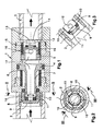
- Figure 1 shows the device according to the invention in longitudinal section and at Installation in a water pipe between the first (2) and second (3) Water pipes.
- Figure 2 is the section II-II shown in Figure 1.
- Figure 3 is the section III-III shown in Figure 2.
- FIGS. 4, 5 and 6 show different functional cases that the one in FIG. 1 shown, but the first (2) and second (3) Water pipes are omitted.
- a preferred embodiment is one Safety device against overpressure in water pipes shown, like this Clearly shown in Figures 1-3, comprises a tubular body (1) attached to its ends with connecting devices for a first upstream located water pipe (2) and a second downstream Water pipe (3) is provided, the tubular body (1) in its interior an upstream tubular piston (4) and a downstream closure element with openings (5) contains, which independently sliding and sealing against the tubular body (1) are movably installed.
- the tubular piston (4) is installed and pointing against a first upstream compression spring (6) a piston rod (7) which slides upstream inside a Cap (8) is movable, which is inserted into the tubular body (1) and upstream a closed bottom (9) and side bores (10), which are connected to the first water pipe (2) and which its downstream end with the rest position or the at farthest downstream position of the free end of the Piston rod (7) of the tubular piston (4) are aligned, the one Operating stroke which is larger than the lateral bores (10), wherein a first O-ring seal downstream of these lateral bores (10) (11) is inserted against the closed bottom (9) of the Sealing cap (8) rests.
- the closure element (5) provided with openings is installed and pointing against a second downstream compression spring (12) a closure surface (13) on a second O-ring seal (15) which in the Closure surface is inserted, opposite a passage of the tubular body (1) acts, which is connected to the second water pipe (3). That with Openings provided closure element (5) has side openings (16) which with the second water pipe (3) through the passage (14) of the tubular body (1) communicating.
- the tubular body (1), the tubular piston (4), the closure element (5) provided with openings and the closure cap (8) delimit a pressure chamber (17) inside, which at the same time as the first (2) and second (3) water pipes via the lateral bores (10), the lateral Openings (16) and the passage (14) is in communication.
- the first (6) and second (12) compression springs are pre-determined depending on each Adjusted water pressure values in the chamber (17), the first spring (6) for a water pressure P2 below a pressure P1 with a by standards specified maximum value is designed, while the second spring (12) for a Water pressure P3 is designed with a value that is greater than P2 and less than that maximum value is that for the elements of the water pipe downstream is permissible.
- FIG. 4 shows a functional state in which the pressure P1 is somewhat larger than P2 is for which the first compression spring (6) is designed, the lateral bores (10) of the cap (8) partially through the piston rod (7) of the tubular Pistons (4) are closed, causing a controlled lowering of the pressure in the pressure chamber (17) is caused, adapted to the pressure P1.
- FIG. 6 shows the state in which the pressure P2 exceeds the safety value for which the second compression spring (12) is designed, whereupon the apertured closure member moves downstream until the passage (14) is closed via the second O-ring seal (15) and the device forms a barrier that blocks the pressures from the downstream line isolated in the manner of an electrical fuse.
Landscapes
- Engineering & Computer Science (AREA)
- General Engineering & Computer Science (AREA)
- Mechanical Engineering (AREA)
- Pipe Accessories (AREA)
- Rigid Pipes And Flexible Pipes (AREA)
- Prostheses (AREA)
- Fluid-Pressure Circuits (AREA)
Applications Claiming Priority (2)
| Application Number | Priority Date | Filing Date | Title |
|---|---|---|---|
| ES200201107A ES2214097B1 (es) | 2002-05-16 | 2002-05-16 | Dispositivo de seguridad para circuitos hidraulicos. |
| ES200201107 | 2002-05-16 |
Publications (3)
| Publication Number | Publication Date |
|---|---|
| EP1363053A2 true EP1363053A2 (fr) | 2003-11-19 |
| EP1363053A3 EP1363053A3 (fr) | 2004-01-07 |
| EP1363053B1 EP1363053B1 (fr) | 2006-11-02 |
Family
ID=29266075
Family Applications (1)
| Application Number | Title | Priority Date | Filing Date |
|---|---|---|---|
| EP03010719A Expired - Lifetime EP1363053B1 (fr) | 2002-05-16 | 2003-05-13 | Dispositif de sécurité pour des conduites d'eau |
Country Status (5)
| Country | Link |
|---|---|
| EP (1) | EP1363053B1 (fr) |
| AT (1) | ATE344414T1 (fr) |
| DE (1) | DE50305541D1 (fr) |
| ES (2) | ES2214097B1 (fr) |
| PT (1) | PT1363053E (fr) |
Families Citing this family (2)
| Publication number | Priority date | Publication date | Assignee | Title |
|---|---|---|---|---|
| CN102537455A (zh) * | 2012-02-27 | 2012-07-04 | 太仓凯鑫电子有限公司 | 一种高可靠限速切断阀 |
| CN106704657B (zh) * | 2016-12-08 | 2018-10-26 | 林桂花 | 一种消除粘度影响的恒流量缝隙式进出口 |
Family Cites Families (8)
| Publication number | Priority date | Publication date | Assignee | Title |
|---|---|---|---|---|
| US2656855A (en) * | 1950-04-11 | 1953-10-27 | United Aircraft Prod | Automatic cutoff device |
| FR1501960A (fr) * | 1966-09-30 | 1967-11-18 | Valve hydraulique de sécurité | |
| SE354903B (fr) * | 1970-08-19 | 1973-03-26 | P Waetterbaeck | |
| DE2115290A1 (fr) * | 1971-03-30 | 1972-10-05 | Preuss | |
| US3741241A (en) * | 1971-07-29 | 1973-06-26 | Eaton Corp | Hydraulic fuse |
| US3779273A (en) * | 1971-12-06 | 1973-12-18 | A Stone | Shut off device |
| US4655245A (en) * | 1986-06-13 | 1987-04-07 | Dowty Decoto, Inc. | Hydraulic fuse |
| US6374852B1 (en) * | 2000-08-09 | 2002-04-23 | Brightvalve, Llc | Leak arresting valve |
-
2002
- 2002-05-16 ES ES200201107A patent/ES2214097B1/es not_active Expired - Fee Related
-
2003
- 2003-05-13 DE DE50305541T patent/DE50305541D1/de not_active Expired - Lifetime
- 2003-05-13 PT PT03010719T patent/PT1363053E/pt unknown
- 2003-05-13 EP EP03010719A patent/EP1363053B1/fr not_active Expired - Lifetime
- 2003-05-13 AT AT03010719T patent/ATE344414T1/de not_active IP Right Cessation
-
2005
- 2005-04-12 ES ES200500868A patent/ES2267380B1/es not_active Expired - Fee Related
Non-Patent Citations (1)
| Title |
|---|
| None |
Also Published As
| Publication number | Publication date |
|---|---|
| DE50305541D1 (de) | 2006-12-14 |
| EP1363053A3 (fr) | 2004-01-07 |
| PT1363053E (pt) | 2007-01-31 |
| ES2214097B1 (es) | 2005-07-01 |
| ES2267380B1 (es) | 2008-03-01 |
| ES2214097A1 (es) | 2004-09-01 |
| ATE344414T1 (de) | 2006-11-15 |
| EP1363053B1 (fr) | 2006-11-02 |
| ES2267380A1 (es) | 2007-03-01 |
Similar Documents
| Publication | Publication Date | Title |
|---|---|---|
| DE102017007236B4 (de) | Drosselventil mit proportionalem Überlauf | |
| DE102010063386B4 (de) | Verstellbare Dämpfventileinrichtung | |
| DE3424503C2 (de) | Druckstoß-Dämpfer in Druckgasleitungen | |
| DE2357671A1 (de) | Durchflussbegrenzungsventil | |
| DE102008059436B3 (de) | Hydraulisches Steuerventil für einen einseitig arbeitenden Differentialzylinder | |
| EP0197467A2 (fr) | Soupape de descente freinée et maintenu sans fuites. | |
| DE102010026977B4 (de) | Verfahren zur Schildsteuerung | |
| DE3237103C3 (de) | Sicherheitsventil als Lasthalteventil in der Hebezeughydraulik | |
| DE2504616C2 (de) | Sicherheitsventil für fördernde Bohrlöcher | |
| DE102008059058B3 (de) | Hydraulische Ventilanordnung mit einem einen druckausgeglichen angeordneten Schließkörper aufweisenden Einbauventil | |
| CH684708A5 (de) | Durchfluss-Kontrollventil. | |
| DE2945911C2 (fr) | ||
| DE1675477A1 (de) | Regelventil | |
| DE3907378A1 (de) | Ventilanordnung zum gleichzeitigen oeffnen und absperren zweier getrennter zuleitungen fuer fluessige oder gasfoermige medien | |
| EP1363053B1 (fr) | Dispositif de sécurité pour des conduites d'eau | |
| DE10325178A1 (de) | Proportional-Druckregelventil | |
| DE2717418A1 (de) | Vorrichtung zur druckpruefung und steuerung eines sicherheitsventils | |
| DE3636647C2 (fr) | ||
| CH658895A5 (de) | Druckbegrenzungsventil fuer unter druck stehende fluidleitungen. | |
| DE3137530C2 (de) | Türbetätigungseinrichtung | |
| DE19853320A1 (de) | Druckbegrenzungsventil mit flacher Kennlinie | |
| DE3828025A1 (de) | Daempfungssystem fuer fluid-zylinder | |
| DE3118263A1 (de) | Tuerbetaetigungseinrichtung | |
| DE3715651A1 (de) | Doppelwirkendes sperrventil zum regulieren eines hydraulischen fluidflusses, insbesondere in einem stossdaempfer oder einem fluidfederungselement fuer ein kraftfahrzeug | |
| DE19944808C1 (de) | Druckbegrenzungs- und Drucksicherungsventil für Druckluftbremsanlagen von Kraftfahrzeugen |
Legal Events
| Date | Code | Title | Description |
|---|---|---|---|
| PUAI | Public reference made under article 153(3) epc to a published international application that has entered the european phase |
Free format text: ORIGINAL CODE: 0009012 |
|
| AK | Designated contracting states |
Kind code of ref document: A2 Designated state(s): AT BE BG CH CY CZ DE DK EE ES FI FR GB GR HU IE IT LI LU MC NL PT RO SE SI SK TR |
|
| AX | Request for extension of the european patent |
Extension state: AL LT LV MK |
|
| PUAL | Search report despatched |
Free format text: ORIGINAL CODE: 0009013 |
|
| RIC1 | Information provided on ipc code assigned before grant |
Ipc: 7F 16K 17/30 A Ipc: 7G 05D 16/10 B |
|
| AK | Designated contracting states |
Kind code of ref document: A3 Designated state(s): AT BE BG CH CY CZ DE DK EE ES FI FR GB GR HU IE IT LI LU MC NL PT RO SE SI SK TR |
|
| AX | Request for extension of the european patent |
Extension state: AL LT LV MK |
|
| 17P | Request for examination filed |
Effective date: 20040707 |
|
| AKX | Designation fees paid |
Designated state(s): AT BE BG CH CY CZ DE DK EE ES FI FR GB GR HU IE IT LI LU MC NL PT RO SE SI SK TR |
|
| GRAP | Despatch of communication of intention to grant a patent |
Free format text: ORIGINAL CODE: EPIDOSNIGR1 |
|
| RAP1 | Party data changed (applicant data changed or rights of an application transferred) |
Owner name: VALVULAS ARCO, S.L. |
|
| GRAS | Grant fee paid |
Free format text: ORIGINAL CODE: EPIDOSNIGR3 |
|
| GRAA | (expected) grant |
Free format text: ORIGINAL CODE: 0009210 |
|
| AK | Designated contracting states |
Kind code of ref document: B1 Designated state(s): AT BE BG CH CY CZ DE DK EE ES FI FR GB GR HU IE IT LI LU MC NL PT RO SE SI SK TR |
|
| PG25 | Lapsed in a contracting state [announced via postgrant information from national office to epo] |
Ref country code: SK Free format text: LAPSE BECAUSE OF FAILURE TO SUBMIT A TRANSLATION OF THE DESCRIPTION OR TO PAY THE FEE WITHIN THE PRESCRIBED TIME-LIMIT Effective date: 20061102 Ref country code: SI Free format text: LAPSE BECAUSE OF FAILURE TO SUBMIT A TRANSLATION OF THE DESCRIPTION OR TO PAY THE FEE WITHIN THE PRESCRIBED TIME-LIMIT Effective date: 20061102 Ref country code: NL Free format text: LAPSE BECAUSE OF FAILURE TO SUBMIT A TRANSLATION OF THE DESCRIPTION OR TO PAY THE FEE WITHIN THE PRESCRIBED TIME-LIMIT Effective date: 20061102 Ref country code: FI Free format text: LAPSE BECAUSE OF FAILURE TO SUBMIT A TRANSLATION OF THE DESCRIPTION OR TO PAY THE FEE WITHIN THE PRESCRIBED TIME-LIMIT Effective date: 20061102 Ref country code: IE Free format text: LAPSE BECAUSE OF FAILURE TO SUBMIT A TRANSLATION OF THE DESCRIPTION OR TO PAY THE FEE WITHIN THE PRESCRIBED TIME-LIMIT Effective date: 20061102 |
|
| REG | Reference to a national code |
Ref country code: GB Ref legal event code: FG4D Free format text: NOT ENGLISH |
|
| REG | Reference to a national code |
Ref country code: IE Ref legal event code: FG4D Free format text: LANGUAGE OF EP DOCUMENT: GERMAN |
|
| REG | Reference to a national code |
Ref country code: CH Ref legal event code: EP |
|
| REF | Corresponds to: |
Ref document number: 50305541 Country of ref document: DE Date of ref document: 20061214 Kind code of ref document: P |
|
| REG | Reference to a national code |
Ref country code: PT Ref legal event code: SC4A Free format text: AVAILABILITY OF NATIONAL TRANSLATION Effective date: 20061130 |
|
| REG | Reference to a national code |
Ref country code: RO Ref legal event code: EPE |
|
| PG25 | Lapsed in a contracting state [announced via postgrant information from national office to epo] |
Ref country code: SE Free format text: LAPSE BECAUSE OF FAILURE TO SUBMIT A TRANSLATION OF THE DESCRIPTION OR TO PAY THE FEE WITHIN THE PRESCRIBED TIME-LIMIT Effective date: 20070202 Ref country code: DK Free format text: LAPSE BECAUSE OF FAILURE TO SUBMIT A TRANSLATION OF THE DESCRIPTION OR TO PAY THE FEE WITHIN THE PRESCRIBED TIME-LIMIT Effective date: 20070202 Ref country code: BG Free format text: LAPSE BECAUSE OF FAILURE TO SUBMIT A TRANSLATION OF THE DESCRIPTION OR TO PAY THE FEE WITHIN THE PRESCRIBED TIME-LIMIT Effective date: 20070202 |
|
| PG25 | Lapsed in a contracting state [announced via postgrant information from national office to epo] |
Ref country code: ES Free format text: LAPSE BECAUSE OF FAILURE TO SUBMIT A TRANSLATION OF THE DESCRIPTION OR TO PAY THE FEE WITHIN THE PRESCRIBED TIME-LIMIT Effective date: 20070213 |
|
| REG | Reference to a national code |
Ref country code: GR Ref legal event code: EP Ref document number: 20070400960 Country of ref document: GR |
|
| NLV1 | Nl: lapsed or annulled due to failure to fulfill the requirements of art. 29p and 29m of the patents act | ||
| ET | Fr: translation filed | ||
| GBV | Gb: ep patent (uk) treated as always having been void in accordance with gb section 77(7)/1977 [no translation filed] |
Effective date: 20061102 |
|
| REG | Reference to a national code |
Ref country code: IE Ref legal event code: FD4D |
|
| PLBE | No opposition filed within time limit |
Free format text: ORIGINAL CODE: 0009261 |
|
| STAA | Information on the status of an ep patent application or granted ep patent |
Free format text: STATUS: NO OPPOSITION FILED WITHIN TIME LIMIT |
|
| REG | Reference to a national code |
Ref country code: HU Ref legal event code: AG4A Ref document number: E001899 Country of ref document: HU |
|
| 26N | No opposition filed |
Effective date: 20070803 |
|
| PG25 | Lapsed in a contracting state [announced via postgrant information from national office to epo] |
Ref country code: GB Free format text: LAPSE BECAUSE OF FAILURE TO SUBMIT A TRANSLATION OF THE DESCRIPTION OR TO PAY THE FEE WITHIN THE PRESCRIBED TIME-LIMIT Effective date: 20061102 |
|
| REG | Reference to a national code |
Ref country code: CH Ref legal event code: PL |
|
| PG25 | Lapsed in a contracting state [announced via postgrant information from national office to epo] |
Ref country code: MC Free format text: LAPSE BECAUSE OF NON-PAYMENT OF DUE FEES Effective date: 20070531 |
|
| PG25 | Lapsed in a contracting state [announced via postgrant information from national office to epo] |
Ref country code: CH Free format text: LAPSE BECAUSE OF NON-PAYMENT OF DUE FEES Effective date: 20070531 Ref country code: LI Free format text: LAPSE BECAUSE OF NON-PAYMENT OF DUE FEES Effective date: 20070531 |
|
| PG25 | Lapsed in a contracting state [announced via postgrant information from national office to epo] |
Ref country code: AT Free format text: LAPSE BECAUSE OF NON-PAYMENT OF DUE FEES Effective date: 20070513 |
|
| PG25 | Lapsed in a contracting state [announced via postgrant information from national office to epo] |
Ref country code: EE Free format text: LAPSE BECAUSE OF FAILURE TO SUBMIT A TRANSLATION OF THE DESCRIPTION OR TO PAY THE FEE WITHIN THE PRESCRIBED TIME-LIMIT Effective date: 20061102 |
|
| PG25 | Lapsed in a contracting state [announced via postgrant information from national office to epo] |
Ref country code: LU Free format text: LAPSE BECAUSE OF NON-PAYMENT OF DUE FEES Effective date: 20070513 |
|
| PG25 | Lapsed in a contracting state [announced via postgrant information from national office to epo] |
Ref country code: TR Free format text: LAPSE BECAUSE OF FAILURE TO SUBMIT A TRANSLATION OF THE DESCRIPTION OR TO PAY THE FEE WITHIN THE PRESCRIBED TIME-LIMIT Effective date: 20061102 |
|
| PGFP | Annual fee paid to national office [announced via postgrant information from national office to epo] |
Ref country code: CZ Payment date: 20100506 Year of fee payment: 8 Ref country code: IT Payment date: 20100525 Year of fee payment: 8 |
|
| PGFP | Annual fee paid to national office [announced via postgrant information from national office to epo] |
Ref country code: CY Payment date: 20100517 Year of fee payment: 8 |
|
| PG25 | Lapsed in a contracting state [announced via postgrant information from national office to epo] |
Ref country code: CZ Free format text: LAPSE BECAUSE OF NON-PAYMENT OF DUE FEES Effective date: 20110513 |
|
| PG25 | Lapsed in a contracting state [announced via postgrant information from national office to epo] |
Ref country code: CY Free format text: LAPSE BECAUSE OF NON-PAYMENT OF DUE FEES Effective date: 20110513 Ref country code: IT Free format text: LAPSE BECAUSE OF NON-PAYMENT OF DUE FEES Effective date: 20110513 |
|
| REG | Reference to a national code |
Ref country code: FR Ref legal event code: PLFP Year of fee payment: 14 |
|
| PGFP | Annual fee paid to national office [announced via postgrant information from national office to epo] |
Ref country code: DE Payment date: 20160527 Year of fee payment: 14 Ref country code: GR Payment date: 20160527 Year of fee payment: 14 |
|
| PGFP | Annual fee paid to national office [announced via postgrant information from national office to epo] |
Ref country code: BE Payment date: 20160527 Year of fee payment: 14 Ref country code: FR Payment date: 20160530 Year of fee payment: 14 Ref country code: RO Payment date: 20160510 Year of fee payment: 14 Ref country code: HU Payment date: 20160509 Year of fee payment: 14 Ref country code: PT Payment date: 20160506 Year of fee payment: 14 |
|
| REG | Reference to a national code |
Ref country code: DE Ref legal event code: R119 Ref document number: 50305541 Country of ref document: DE |
|
| PG25 | Lapsed in a contracting state [announced via postgrant information from national office to epo] |
Ref country code: RO Free format text: LAPSE BECAUSE OF NON-PAYMENT OF DUE FEES Effective date: 20170513 Ref country code: HU Free format text: LAPSE BECAUSE OF NON-PAYMENT OF DUE FEES Effective date: 20170514 |
|
| PG25 | Lapsed in a contracting state [announced via postgrant information from national office to epo] |
Ref country code: GR Free format text: LAPSE BECAUSE OF NON-PAYMENT OF DUE FEES Effective date: 20171206 Ref country code: PT Free format text: LAPSE BECAUSE OF NON-PAYMENT OF DUE FEES Effective date: 20171113 |
|
| REG | Reference to a national code |
Ref country code: FR Ref legal event code: ST Effective date: 20180131 |
|
| REG | Reference to a national code |
Ref country code: BE Ref legal event code: MM Effective date: 20170531 |
|
| PG25 | Lapsed in a contracting state [announced via postgrant information from national office to epo] |
Ref country code: DE Free format text: LAPSE BECAUSE OF NON-PAYMENT OF DUE FEES Effective date: 20171201 |
|
| PG25 | Lapsed in a contracting state [announced via postgrant information from national office to epo] |
Ref country code: FR Free format text: LAPSE BECAUSE OF NON-PAYMENT OF DUE FEES Effective date: 20170531 |
|
| PG25 | Lapsed in a contracting state [announced via postgrant information from national office to epo] |
Ref country code: BE Free format text: LAPSE BECAUSE OF NON-PAYMENT OF DUE FEES Effective date: 20170531 |