EP1363135A2 - Procédé et appareil pour découplage des éléments dans un réseau de détecteur pour l'imagerie par résonance magnétique - Google Patents
Procédé et appareil pour découplage des éléments dans un réseau de détecteur pour l'imagerie par résonance magnétique Download PDFInfo
- Publication number
- EP1363135A2 EP1363135A2 EP03253029A EP03253029A EP1363135A2 EP 1363135 A2 EP1363135 A2 EP 1363135A2 EP 03253029 A EP03253029 A EP 03253029A EP 03253029 A EP03253029 A EP 03253029A EP 1363135 A2 EP1363135 A2 EP 1363135A2
- Authority
- EP
- European Patent Office
- Prior art keywords
- detector
- detector array
- decoupling
- array
- elements
- Prior art date
- Legal status (The legal status is an assumption and is not a legal conclusion. Google has not performed a legal analysis and makes no representation as to the accuracy of the status listed.)
- Ceased
Links
- 238000002595 magnetic resonance imaging Methods 0.000 title claims abstract description 40
- 238000000034 method Methods 0.000 title claims abstract description 31
- 239000011159 matrix material Substances 0.000 claims description 37
- 239000003990 capacitor Substances 0.000 claims description 22
- 230000008878 coupling Effects 0.000 description 17
- 238000010168 coupling process Methods 0.000 description 17
- 238000005859 coupling reaction Methods 0.000 description 17
- 238000003384 imaging method Methods 0.000 description 12
- 238000003491 array Methods 0.000 description 5
- 230000005855 radiation Effects 0.000 description 5
- 230000005540 biological transmission Effects 0.000 description 4
- 238000010586 diagram Methods 0.000 description 4
- 230000035945 sensitivity Effects 0.000 description 4
- RYGMFSIKBFXOCR-UHFFFAOYSA-N Copper Chemical compound [Cu] RYGMFSIKBFXOCR-UHFFFAOYSA-N 0.000 description 3
- 229910052802 copper Inorganic materials 0.000 description 3
- 239000010949 copper Substances 0.000 description 3
- 230000008901 benefit Effects 0.000 description 2
- 239000004020 conductor Substances 0.000 description 2
- 229940079593 drug Drugs 0.000 description 2
- 239000003814 drug Substances 0.000 description 2
- 230000005284 excitation Effects 0.000 description 2
- 239000011521 glass Substances 0.000 description 2
- 230000006872 improvement Effects 0.000 description 2
- 230000001965 increasing effect Effects 0.000 description 2
- 230000001939 inductive effect Effects 0.000 description 2
- 239000000463 material Substances 0.000 description 2
- 230000007246 mechanism Effects 0.000 description 2
- 238000001208 nuclear magnetic resonance pulse sequence Methods 0.000 description 2
- 230000009467 reduction Effects 0.000 description 2
- 239000013598 vector Substances 0.000 description 2
- 238000010276 construction Methods 0.000 description 1
- 230000001419 dependent effect Effects 0.000 description 1
- 230000008021 deposition Effects 0.000 description 1
- 238000002474 experimental method Methods 0.000 description 1
- 230000002349 favourable effect Effects 0.000 description 1
- 239000010437 gem Substances 0.000 description 1
- 238000011503 in vivo imaging Methods 0.000 description 1
- 238000002955 isolation Methods 0.000 description 1
- 230000008569 process Effects 0.000 description 1
- 230000001105 regulatory effect Effects 0.000 description 1
- 238000000926 separation method Methods 0.000 description 1
- 238000001228 spectrum Methods 0.000 description 1
- 230000009466 transformation Effects 0.000 description 1
Images



Classifications
-
- G—PHYSICS
- G01—MEASURING; TESTING
- G01R—MEASURING ELECTRIC VARIABLES; MEASURING MAGNETIC VARIABLES
- G01R33/00—Arrangements or instruments for measuring magnetic variables
- G01R33/20—Arrangements or instruments for measuring magnetic variables involving magnetic resonance
- G01R33/28—Details of apparatus provided for in groups G01R33/44 - G01R33/64
- G01R33/32—Excitation or detection systems, e.g. using radio frequency signals
- G01R33/36—Electrical details, e.g. matching or coupling of the coil to the receiver
- G01R33/3642—Mutual coupling or decoupling of multiple coils, e.g. decoupling of a receive coil from a transmission coil, or intentional coupling of RF coils, e.g. for RF magnetic field amplification
- G01R33/365—Decoupling of multiple RF coils wherein the multiple RF coils have the same function in MR, e.g. decoupling of a receive coil from another receive coil in a receive coil array, decoupling of a transmission coil from another transmission coil in a transmission coil array
Definitions
- This invention relates generally to magnetic resonance imaging (MRI), and more particularly, to decoupling radio frequency (RF) detector arrays used for MRI.
- MRI magnetic resonance imaging
- RF radio frequency
- MRI is a well-known imaging technique.
- a conventional MRI device establishes a homogenous magnetic field, for example, along an axis of a person's body that is to undergo MRI.
- This homogeneous magnetic field conditions the interior of the person's body for imaging by aligning the nuclear spins of nuclei (in atoms and molecules forming the body tissue) along the axis of the magnetic field. If the orientation of the nuclear spin is perturbed out of alignment with the magnetic field, the nuclei attempt to realign their nuclear spins with an axis of the magnetic field. Perturbation of the orientation of nuclear spins may be caused by application of radio frequency (RF) pulses. During the realignment process, the nuclei precess about the axis of the magnetic field and emit electromagnetic signals that may be detected by one or more coils placed on or about the person.
- RF radio frequency
- the frequency of the magnetic resonance (MR) signal emitted by a given precessing nucleus depends on the strength of the magnetic field at the nucleus' location. As is well known in the art, it is possible to distinguish radiation originating from different locations within the person's body by applying a field gradient to the magnetic field across the person's body. For the sake of convenience, direction of this field gradient may be referred to as the left-to-right direction. Radiation of a particular frequency may be assumed to originate at a given position within the field gradient, and hence at a given left-to-right position within the person's body. The application of such a field gradient is also referred to as frequency encoding.
- the application of a field gradient does not allow for two-dimensional resolution, since all nuclei at a given left-to-right position experience the same field strength, and hence emit radiation of the same frequency. Accordingly, the application of a frequency-encoding gradient, by itself, does not make it possible to discern radiation originating from the top versus radiation originating from the bottom of the person at a given left-to-right position. Resolution has been found to be possible in this second direction by application of gradients of varied strength in a perpendicular direction to thereby perturb the nuclei in varied amounts. The application of such additional gradients is also referred to as phase encoding.
- Frequency-encoded data sensed by the coils during a phase encoding step is stored as a line of data in a data matrix known as the k-space matrix. Multiple phase encoding steps are performed in order to fill the multiple lines of the k-space matrix.
- An image may be generated from this matrix by performing a Fourier transformation of the matrix to convert this frequency information to spatial information representing the distribution of nuclear spins or density of nuclei of the image material.
- Imaging time is largely a factor of desired signal-to-noise ratio (SNR) and the speed with which the MRI device can fill the k-space matrix.
- SNR signal-to-noise ratio
- the k-space matrix is filled one line at a time.
- the speed with which the k-space matrix may be filled is limited.
- several techniques have been developed to simultaneously acquire multiple lines of data for each application of a magnetic field gradient. These techniques, which may collectively be characterized as "parallel imaging techniques", use spatial information from arrays of RF detector coils to substitute for the encoding which would otherwise have to be obtained in a sequential fashion using field gradients and RF pulses.
- the use of multiple effective detectors has been shown to multiply imaging speed, without increasing gradient switching rates or RF power deposition.
- SENSE SENSitivity Encoding
- SMASH simultaneous acquisition of spatial harmonics
- Both techniques include the parallel use of a plurality of separate receiving elements, with each element having a different respective sensitivity profile, and combination of the respective spin resonance signals detected enables a reduction of the acquisition time required for an image (in comparison with conventional Fourier image reconstruction) by a factor which in the most favorable case equals the number of the receiving members used (see Pruessmann et al., Magnetic Resonance in Medicine Vol. 42, p.952-962, 1999).
- a drawback of the SENSE technique results when the component coil sensitivities are either insufficiently well characterized or insufficiently distinct from one another. These instabilities may manifest as localized artifacts in the reconstructed image, or may result in degraded signal to noise ratio (SNR). Accordingly, it is desirable to implement RF coil arrays in MRI systems that (among other aspects) provide increased SNR with or without the use of parallel imaging techniques such as SENSE.
- image artifacts are also attributable due to the mutual couplings between coils in a cluster of closely situated surface coils, which have been separately tuned and matched.
- the mutual couplings between the coils generate coupled modes, which cause splitting in the coils' resonant spectrum. Consequently, the coils become detuned and mismatched, causing reductions in the SNR.
- some decoupling mechanisms are needed to degenerate the multiple coupled modes into a single mode that resonates at the MR frequency.
- adjacent coils are provided for receiving signals during imaging.
- a low impedance preamplifier is used for the coils not contained within an overlapping pair. Due to the current-carrying paths established by each coil of the array, such overlapping and preamplifier configuration reduces and/or cancels mutual inductive coupling between the coils, thereby reducing cross talk.
- a radio frequency (RF) detector array assembly for use in a magnetic resonance imaging (MRI) system.
- the RF detector array assembly comprises at least one array of RF detectors, wherein the array has a plurality of RF detector elements for use in acquiring radio frequency (RF) signals from the MRI system, and, a decoupling interface coupled to each of the plurality of detector elements for decoupling each detector element from the remaining detector elements.
- RF radio frequency
- a method for decoupling radio frequency (RF) detector array elements in a magnetic resonance imaging (MRI) system comprises the steps of providing at least one RF detector array, wherein the detector array has a plurality of RF detector elements, and, providing a decoupling interface coupled to each of the plurality of detector elements for decoupling each detector element from the remaining detector elements.
- RF radio frequency
- an exemplary magnetic resonance (MR) imaging system includes a computer 10, which controls gradient coil power amplifiers 14 through a pulse control module 12.
- the pulse control module 12 and the gradient amplifiers 14 together produce the proper gradient waveforms Gx, Gy, and Gz, for either a spin echo, a gradient recalled echo pulse sequence, a fast spin echo, or other type of pulse sequences.
- the gradient waveforms are connected to gradient coils 16, which are positioned around the bore of an MR magnet assembly 34 so that gradients Gx, Gy, and Gz are impressed along their respective axes on the polarizing magnetic field B 0 from magnet assembly 34.
- the pulse control module 12 also controls a radio frequency synthesizer 18 that is part of an RF transceiver system, portions of which are enclosed by dashed line block 36.
- the pulse control module 12 also controls an RF modulator 20, which modulates the output of the radio frequency synthesizer 18.
- the resultant RF signals amplified by power amplifier 22 and applied to a RF coil assembly 26 through transmit/receive switch 24, are used to excite the nuclear spins of the imaged object (not shown).
- the MR signals from the excited nuclei of the imaged object are picked up by RF coil assembly 26 and presented to preamplifier 28 through transmit/receive switch 24, to be amplified and then processed by a quadrature phase detector 30.
- the detected signals are digitized by a high speed A/D converter 32 and applied to computer 10 for processing to produce MR images of the object.
- Computer 10 also controls shimming coil power supplies 38 to power shimming coil assembly 40.
- RF coil assembly 26 is a RF detector array consisting of multiple detector elements, such as loops or conductive strips and may also be configured as an array of multiple coils or conductive strips. Other conductive materials and structures, for example copper rods, pipes, wires or other line structures, may also be used as detector elements.
- RF coil assembly 26 is a MRI phased array. An embodiment employing conductive strips will be described in greater detail below with reference to Figures 2 and 3. Also, in embodiment of the present invention, the detector elements may be non-overlapping or over-lapping.
- the SNR may be even further improved by implementing a multiple channel array for receive coil assembly 26.
- a parallel processing technique such as SENSE (described above) may then be used to improve data acquisition time.
- SENSE a parallel processing technique
- B 0 field strengths e.g., > 3T
- the homogeneity of the RF excitation field becomes largely dependent upon the electrical properties and size of the patient.
- the transmit coil were also implemented in an array configuration, then the current amplitude and phase in each array element could be individually regulated such that the homogeneity of the RF excitation field is optimized in the presence of the patient.
- microstrip array 100 which may be subsequently configured in a generally planar configuration for RF detector applications such as a surface coil.
- microstrip array 100 may be configured in a cylindrical fashion to form a multiple channel volume resonator.
- the array 100 includes a series of parallel, commensurate-length conductive (e.g., copper) microstrips 102 having a dielectric overlay 104 thereon.
- the dielectric medium material reduces the electromagnetic frequency (EMF) wavelength by a factor of ⁇ r 1 ⁇ 2 in order to make, for example, a quarter wavelength ( ⁇ /4) resonator at the MRI frequency correspond to a reasonable length for a receiving array.
- EMF electromagnetic frequency
- ⁇ /4 quarter wavelength
- the quarter wavelength ( ⁇ /4) is reduced from 117 cm to 46 cm in the glass medium.
- the volume resonator may be used as either a 16-channel phased array for SNR improvement, or for parallel image processing techniques such as SENSE.
- the strip length / can be a quarter wavelength ( ⁇ /4) or a half wavelength ( ⁇ /2), while the strip width w , spacing s, and dielectric thickness h are chosen to make the characteristic impedance of the strip match the impedance of connecting cables thereto (not shown).
- One advantage of the microstrip array 100 over a conventional loop design is that the length of the strips 102 may be adjusted such that the coupling between the strips is minimized, regardless of the spacing s therebetween.
- using a group of quarter wavelength ( ⁇ /4) strips (or integral multiples thereof) terminated by either an open circuit or a short circuit results in standing wave resonance within the strips.
- ⁇ /2 strips or integral multiples thereof terminating with matched impedance loads results in traveling wave resonance within the strip.
- the strips are decoupled from one another (as is described in greater detail by Lee, et al.), thereby providing high SNR on each of the isolated strips.
- the actual physical length of the strip array may be allowed to vary, so long as the desired electrical wavelength of the strip is achieved.
- the physical length of the strip can be varied to alter the electrical wavelength of the strip.
- the electrical length ⁇ 0 should desirably be ⁇ /2 or ⁇ , which requires the physical length be a quarter or a half, wavelength of the resonant wavelength.
- the resonant wavelength in air is about 1 m, therefore the quarter wavelength of a conductive strip in air is 25 cm, which is a reasonable length for a RF detector inside a MRI scanner.
- FIG. 3 schematically illustrates a pair of strips (a), (b) represented as transmission lines.
- the actual strip length l is equal to a desired electrical wavelength ⁇ 0 (e.g., ⁇ /4, ⁇ /2).
- ⁇ 0 e.g., ⁇ /4, ⁇ /2
- strip (b) the actual strip length / is shorter than the desired electrical wavelength ⁇ 0 , instead having an electrical wavelength ⁇ .
- lumped elements such as capacitors C1 and C2 may be added to strip (b).
- a radio frequency (RF) detector array assembly for use in parallel imaging.
- a radio frequency (RF) detector array assembly is provided for use in a MRI system.
- the RF detector array assembly comprises at least one RF detector array 410, as described above wherein the array has a plurality of RF detector elements for use in simultaneously acquiring RF signals from the MRI system, and a decoupling interface 420 coupled to each of the plurality of detector elements for decoupling each element from the remaining elements.
- the array may be a phased array, a multiple coil array or, alternatively, a microstrip array.
- the elements, for example coils or strips, may be non-overlapping or overlapping. In the embodiments described hereinafter, the coils and/or strips are referred to as "elements" and are non-overlapping. It is to be appreciated that the decoupling interface arrangement is also applicable to arrays having overlapping elements.
- the array comprises a plurality of conductive strips 102 being substantially parallel to a conductive ground plane (not shown) and a plurality of capacitors C1 and C2 of Figure 3, wherein at least one capacitor is shunted from each strip to the ground plane to adjust a corresponding electrical length of each conductive strip.
- the combination of each respective strip, at least one corresponding capacitor and the ground plane forms a resonator that resonates at a selected frequency.
- the array comprises a plurality of commensurate microstrips formed within a dielectric medium, each microstrip being adjusted to an integer multiple of a quarter-wavelength of a selected resonance wavelength by adjusting both strip length and a dielectric constant of the medium and at least one termination at each microstrip, the termination being selected from a group consisting of short circuit, open circuit, and reactive terminations.
- n-port systems represent n -element array for use in detecting RF signals in a MRI system.
- the system further has a number n or ports for coupling to, for example, source generators.
- the source generators are the equivalent voltage or current sources at the outputs of power amplifiers to the MRI system.
- the source generators represent the signals at preamplifier inputs of the MRI system.
- the real part of Z ii represents transformed resistive losses in the element (e.g. sample losses) while the imaginary part is the transformed reactance of the element.
- the real part of Z ij is the mutual resistance (associated with noise correlation) between coil elements i and j
- the imaginary part of Z ij is the reactive coupling, which is mainly inductive coupling between coil elements i and j .
- the uncoupled system can be treated as a special case of the general coupled system.
- V u and I u be the voltage and current vectors measured at the ports in the uncoupled system.
- Z u and Y u are the open-circuit impedance and admittance matrices for the uncoupled system:
- the generator impedance and admittance are identical to The generator impedance and admittance.
- V g V u + Z g I u
- I g I u + Y g V u .
- Equations [7] and [8] are the foundation for developing the relations between the coupled and uncoupled phased array.
- Equation [7] is the complete description of a coupled system.
- Equation [8] is the complete description of an uncoupled system.
- C V is called the voltage coupling matrix
- D V is called the voltage decoupling matrix
- C I is called the current coupling matrix
- D I is called the current decoupling matrix
- the coupling of an n -port system can be fully characterized by the voltage and the current coupling matrices C V and C I .
- Each eigenvalue of C v or C I represents one coupled mode. Since C V or C I is an n x n matrix, if there is no degeneracy, then there can be n coupled modes, which suggests that coupling could cause the system's resonance frequency to split into n different frequencies.
- One way to handle MR signals in such a coupled system is to include an additional decoupling mechanism to degenerate the multiple resonant modes of the system into one mode.
- a coupled n -port system with impedance matrix Z is transformed into a decoupled n -port system Z u by a 2 n -port interface system with impedance matrix Z' , as illustrated in Fig. 4.
- Z' is a 2 n x2 n matrix, expressed as follows
- the nodal equation of the 2 n -port interface system is where
- Any 2 n -port interface that satisfies Eq. [23] can be used to decouple an n -port coupled system Z.
- the matrix Z' is a 2 n x 2 n matrix, and so if it also has the reciprocity of a passive network and identical diagonal elements, it has 1+2 n (2 n -1)/2 unknowns. Because the number of unknowns is larger than the number of independent equations, the decoupling equation Eq. [23] has more than one set of solutions, which means that there is more than one way to construct the decoupling network.
- a four-port decoupling interface was used to decouple two strongly coupled coils and was experimentally demonstrated with both a network analyzer and a MRI scanner.
- the coupling measured between two identical surface coils was -1.4dB when they were unloaded, and -5dB when they were loaded with a human chest.
- the coupling S21 reduced to -33dB when they were unloaded, and -51dB when they were loaded with a human chest. This means that there is only about 0.3% signal-power cross-talk between the two coils assuming that the input impedance of the preamplifier is 50 ⁇ .
- each coil was constructed with 0.25mm thick and 602g/m 2 flexible printed circuit board. A total of four such coils were separately tuned at 63.66MHz, and matched to 50 ⁇ when they were loaded with a human chest. The two coils, coil 1 and 2, were laid side-by-side without any overlapping, and placed on a fixture to serve as an MRI RF detector. The separation between these two coils was 7mm. A half wavelength coaxial cable is connected to each coil via a balun. The strong coupling between these two coils was recorded by an HP 4395A impedance/network analyzer (Hewlett Packard, Palo Alto, CA) and by an MRI scanner GE Lx (GEMS, Milwaukee, WI.
- HP 4395A impedance/network analyzer Hewlett Packard, Palo Alto, CA
- MRI scanner GE Lx GEMS, Milwaukee, WI.
- the decoupling interface in this experiment was made from two coils, coil 3 and coil 4, which are outside the magnet of the MRI scanner.
- Coil 3 is connected with both coil 1 and a preamplifier with a BNC T-connector
- coil 4 is connected with both coil 2 and another preamplifier with another T-connector. Adjusting the overlap between coil 3 and coil 4 can achieve the proper mutual reactance to decouple coil 1 and coil 2.
- the reason for using two coils as a decoupling interface is because they are relatively easy to adjust to show a variety of coupling and decoupling phenomena, and because no extra matching is needed for every adjustment.
- the interfaces may also be constructed with lumped-element circuits to minimize losses in the interface, such as interface would need to be inserted before any matching is performed.
- Figure 5 is a schematic illustration of this exemplary embodiment.
- decoupling interface 420 may comprise reactive lumped-element circuits, distributive structures, transmission lines and coils.
- Figure 6 shows a ⁇ -circuit 610 acting as a decoupling interface for coil circuit 600, which is an equivalent circuit for two coils (Coil 1 and 2) of an array as described in Figure 5.
- Figure 7 shows a T-circuit 710 acting as a decoupling interface for coil circuit 700, which is also an equivalent circuit for the two coils Coil 1 and 2 of the array shown in Figure 5.
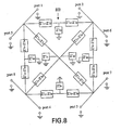
- FIG. 8 there is shown a block diagram of an eight-port decoupling interface for decoupling a four-element phased array 800. This interface is assembled from six four-port interfaces.
- FIG. 9 there is shown a block diagram of a further embodiment of a RF detector array showing tuning capacitors 910 in shunt connection with a ground plane (not shown), matching capacitors 920 between conductive element segments 900 and decoupling capacitors 930 for interconnecting as described above.
- a method for decoupling radio frequency (RF) detector array elements in a magnetic resonance imaging (MRI) system comprises the steps of providing at least one of a RF detector array and providing a decoupling interface coupled to each of the plurality of detector elements for decoupling each detector element from the remaining detector elements.
- the RF detector array has a plurality of RF detector elements. In one embodiment, the detector elements are non-overlapping. In another embodiment, the detector elements are overlapping.
Landscapes
- Physics & Mathematics (AREA)
- Condensed Matter Physics & Semiconductors (AREA)
- General Physics & Mathematics (AREA)
- Magnetic Resonance Imaging Apparatus (AREA)
Applications Claiming Priority (2)
| Application Number | Priority Date | Filing Date | Title |
|---|---|---|---|
| US63843 | 2002-05-17 | ||
| US10/063,843 US6727703B2 (en) | 2002-05-17 | 2002-05-17 | Method and apparatus for decoupling RF detector arrays for magnetic resonance imaging |
Publications (2)
| Publication Number | Publication Date |
|---|---|
| EP1363135A2 true EP1363135A2 (fr) | 2003-11-19 |
| EP1363135A3 EP1363135A3 (fr) | 2005-07-20 |
Family
ID=29268593
Family Applications (1)
| Application Number | Title | Priority Date | Filing Date |
|---|---|---|---|
| EP03253029A Ceased EP1363135A3 (fr) | 2002-05-17 | 2003-05-15 | Procédé et appareil pour découplage des éléments dans un réseau de détecteur pour l'imagerie par résonance magnétique |
Country Status (4)
| Country | Link |
|---|---|
| US (1) | US6727703B2 (fr) |
| EP (1) | EP1363135A3 (fr) |
| JP (1) | JP4579504B2 (fr) |
| CN (2) | CN101526593B (fr) |
Cited By (3)
| Publication number | Priority date | Publication date | Assignee | Title |
|---|---|---|---|---|
| GB2490548A (en) * | 2011-05-06 | 2012-11-07 | Renishaw Plc | Dual frequency MRI RF coil assembly on flexible substrate |
| WO2014053289A1 (fr) * | 2012-10-02 | 2014-04-10 | Koninklijke Philips N.V. | Bobine à corps en cage d'oiseau pour irm à transmission parallèle |
| US9885766B2 (en) | 2012-04-17 | 2018-02-06 | Transarray LLC | Magnetic-resonance transceiver-phased array that compensates for reactive and resistive components of mutual impedance between array elements and circuit and method thereof |
Families Citing this family (33)
| Publication number | Priority date | Publication date | Assignee | Title |
|---|---|---|---|---|
| AU2002353183A1 (en) * | 2001-12-31 | 2003-07-24 | The Johns Hopkins University School Of Medicine | Mri tunable antenna and system |
| US6927575B2 (en) * | 2003-01-21 | 2005-08-09 | General Electric Company | Surface coil decoupling means for MRI systems |
| DE10334170B3 (de) * | 2003-07-26 | 2005-06-02 | Physikalisch-Technische Bundesanstalt Braunschweig Und Berlin | Anordnung zum Erzeugen von Hochfrequenz-B1-Feldern in der NMR mit Flächenstromantennen |
| US7282915B2 (en) * | 2004-05-14 | 2007-10-16 | General Electric Company | Multi-turn element RF coil array for multiple channel MRI |
| CN100372500C (zh) * | 2004-07-02 | 2008-03-05 | 西门子(中国)有限公司 | 磁共振成像系统阵列接收线圈 |
| US7898252B2 (en) * | 2005-03-10 | 2011-03-01 | University Of Queensland | Phased array coil for MRI |
| US20070190663A1 (en) * | 2005-08-12 | 2007-08-16 | Lee Ray F | System and method for using polarized or hyperpolarized contrast agent to perform parallel magnetic resonance imaging of a sample |
| CN1941500B (zh) * | 2005-09-30 | 2011-10-19 | 西门子(中国)有限公司 | 射频发射线圈的去耦合方法 |
| US7642782B2 (en) * | 2005-10-27 | 2010-01-05 | Koninklijke Philips Electronics N.V. | Active decoupling of transmitters in MRI |
| US7932721B2 (en) * | 2006-04-07 | 2011-04-26 | The United States Of America As Represented By The Department Of Health And Human Services | Inductive decoupling of a RF coil array |
| US7336074B2 (en) * | 2006-05-05 | 2008-02-26 | Quality Electrodynamics | Active decoupling of MRI RF transmit coils |
| US9386939B1 (en) | 2007-05-10 | 2016-07-12 | Fonar Corporation | Magnetic resonance imaging of the spine to detect scoliosis |
| US7816918B2 (en) * | 2007-05-24 | 2010-10-19 | The Johns Hopkins University | Optimized MRI strip array detectors and apparatus, systems and methods related thereto |
| US7616000B2 (en) * | 2007-11-15 | 2009-11-10 | General Electric Company | Ultra low output impedance RF power amplifier for parallel excitation |
| DE102008063460B4 (de) * | 2008-12-17 | 2011-12-01 | Siemens Aktiengesellschaft | Magnetresonanz-Empfangssystem, Übertragungssignal-Empfangsbaugruppe, Magnetresonanzsystem und Verfahren zum Übertragen von MR-Antwortsignalen |
| US8179137B2 (en) * | 2009-03-31 | 2012-05-15 | General Electric Company | Magnetic resonance compatible multichannel stripline balun |
| US8138762B2 (en) * | 2009-08-24 | 2012-03-20 | Imris Inc. | Coil decoupling for an RF coil array |
| US9182463B2 (en) * | 2010-02-26 | 2015-11-10 | Hitachi Medical Corporation | Magnetic resonance examination apparatus and antenna device |
| CN103026251B (zh) * | 2010-05-27 | 2016-05-11 | 皇家飞利浦电子股份有限公司 | Mri rf线圈阵列的多个通道的解耦 |
| US8269499B2 (en) * | 2010-06-01 | 2012-09-18 | Quality Electrodynamics, Llc | Failsafe protection from induced RF current for MRI RF coil assembly having transmit functionality |
| CN103767705B (zh) | 2012-10-23 | 2017-12-22 | 三星电子株式会社 | 磁共振成像系统和磁共振成像方法 |
| CN104871025B (zh) * | 2012-12-20 | 2018-04-27 | 皇家飞利浦有限公司 | 线圈元件的自动去耦 |
| WO2014109757A1 (fr) | 2013-01-11 | 2014-07-17 | Mri Innovations | Système et procédé de découplage de bobine de radiofréquence pour imagerie par résonance magnétique ayant une paroi magnétique modulaire |
| KR101967246B1 (ko) | 2013-01-21 | 2019-04-09 | 삼성전자주식회사 | 자기공명영상 시스템, 데이터 처리장치 및 자기공명영상 생성 방법 |
| US11141080B1 (en) | 2013-03-13 | 2021-10-12 | Fonar Corporation | Cervical vertebra angle measurement |
| US10295624B2 (en) * | 2013-04-01 | 2019-05-21 | Massachusetts Institute Of Technology | Decoupling of parallel transmission arrays in magnetic resonance imaging |
| CN109963507B (zh) * | 2016-11-23 | 2023-07-04 | 通用电气公司 | 用于磁共振成像(mri)系统的前部射频(rf)线圈阵列 |
| KR102270520B1 (ko) * | 2016-11-23 | 2021-06-30 | 제너럴 일렉트릭 캄파니 | 자기 공명 이미징(mri) 시스템을 위한 순응성 후방 무선 주파수(rf) 코일 어레이 |
| CN108627783B (zh) * | 2017-03-23 | 2022-01-14 | 通用电气公司 | 射频线圈阵列及磁共振成像发射阵列 |
| JP7592277B2 (ja) * | 2018-03-28 | 2024-12-02 | 国立研究開発法人量子科学技術研究開発機構 | マイクロストリップ伝送線アレイrfコイル、rfシールド構造、及び、rfコイル・放射線画像化装置一体型デバイス |
| CN109873505B (zh) * | 2019-03-25 | 2020-12-15 | 浙江大学 | 一种无线电能传输系统中单排放置多发射线圈解耦的方法 |
| CN112986881B (zh) * | 2019-12-17 | 2022-12-20 | 上海联影医疗科技股份有限公司 | 磁共振系统校准方法、成像方法以及磁共振系统 |
| CN114415097B (zh) * | 2021-12-31 | 2023-06-30 | 江苏美时医疗技术有限公司 | 一种磁共振相控阵线圈性能快速检测装置及其检测方法 |
Citations (6)
| Publication number | Priority date | Publication date | Assignee | Title |
|---|---|---|---|---|
| EP0390476A2 (fr) | 1989-03-29 | 1990-10-03 | Kabushiki Kaisha Toshiba | Système de bobines pour un appareil d'imagerie par résonance magnétique |
| EP0412824A2 (fr) | 1989-08-09 | 1991-02-13 | Kabushiki Kaisha Toshiba | Système d'imagerie par résonance magnétique |
| US5489847A (en) | 1993-06-08 | 1996-02-06 | Hitachi, Ltd. | RF probe for MRI |
| EP1122551A1 (fr) | 2000-01-18 | 2001-08-08 | Ge Yokogawa Medical Systems, Ltd. | Réseau de bobines r.f. pour l'IRM avec couplage réduit entre les bobines |
| WO2002095435A1 (fr) | 2001-05-19 | 2002-11-28 | Koninklijke Philips Electronics N.V. | Bobine de transmission et de reception pour appareil mr |
| WO2003058283A1 (fr) | 2001-12-31 | 2003-07-17 | The Johns Hopkins University School Of Medicine | Antenne accordable et systeme pour irm |
Family Cites Families (12)
| Publication number | Priority date | Publication date | Assignee | Title |
|---|---|---|---|---|
| US4769605A (en) * | 1986-11-26 | 1988-09-06 | Kabushiki Kaisha Toshiba | Network to cancel coupling between channels of quadrature antenna coil assembly in a magnetic resonance imaging system |
| US4825162A (en) | 1987-12-07 | 1989-04-25 | General Electric Company | Nuclear magnetic resonance (NMR) imaging with multiple surface coils |
| DE4024582C2 (de) * | 1989-08-16 | 1996-08-14 | Siemens Ag | Hochfrequenz-Antenne eines Kernspintomographen |
| JP3197262B2 (ja) * | 1990-02-28 | 2001-08-13 | 株式会社東芝 | 磁気共鳴映像装置 |
| JP3079592B2 (ja) * | 1991-01-31 | 2000-08-21 | 株式会社島津製作所 | Mri用表面コイル |
| BR9305438A (pt) * | 1992-03-13 | 1994-08-02 | Motorola Inc | Rede combinada amplificadora de potência de sinal de radiofrequência (RF) e dispositivo de comunicações de sinal de radiofrequência de modo duplo |
| GB9508635D0 (en) * | 1995-04-28 | 1995-06-14 | Mansfield Peter | Method and apparatus for elimination of mutual coupling in magnetic coils |
| JP3139610B2 (ja) * | 1995-12-04 | 2001-03-05 | 株式会社エヌ・ティ・ティ・ドコモ | マイクロストリップアンテナ装置 |
| US6289232B1 (en) * | 1998-03-30 | 2001-09-11 | Beth Israel Deaconess Medical Center, Inc. | Coil array autocalibration MR imaging |
| US6459265B1 (en) | 1998-11-25 | 2002-10-01 | General Electric Company | Method and apparatus for reducing input impedance of a preamplifier |
| JP4423771B2 (ja) * | 2000-06-27 | 2010-03-03 | ソニー株式会社 | メモリーモジュール |
| EP1344076A1 (fr) * | 2000-10-09 | 2003-09-17 | Regents Of The University Of Minnesota | Procede et appareil d'imagerie par resonance magnetique et de spectroscopie utilisant des bobines a ligne de transmission microruban |
-
2002
- 2002-05-17 US US10/063,843 patent/US6727703B2/en not_active Expired - Fee Related
-
2003
- 2003-05-15 EP EP03253029A patent/EP1363135A3/fr not_active Ceased
- 2003-05-16 JP JP2003138257A patent/JP4579504B2/ja not_active Expired - Fee Related
- 2003-05-16 CN CN200810161959.8A patent/CN101526593B/zh not_active Expired - Lifetime
- 2003-05-16 CN CNB031238157A patent/CN100437137C/zh not_active Expired - Lifetime
Patent Citations (6)
| Publication number | Priority date | Publication date | Assignee | Title |
|---|---|---|---|---|
| EP0390476A2 (fr) | 1989-03-29 | 1990-10-03 | Kabushiki Kaisha Toshiba | Système de bobines pour un appareil d'imagerie par résonance magnétique |
| EP0412824A2 (fr) | 1989-08-09 | 1991-02-13 | Kabushiki Kaisha Toshiba | Système d'imagerie par résonance magnétique |
| US5489847A (en) | 1993-06-08 | 1996-02-06 | Hitachi, Ltd. | RF probe for MRI |
| EP1122551A1 (fr) | 2000-01-18 | 2001-08-08 | Ge Yokogawa Medical Systems, Ltd. | Réseau de bobines r.f. pour l'IRM avec couplage réduit entre les bobines |
| WO2002095435A1 (fr) | 2001-05-19 | 2002-11-28 | Koninklijke Philips Electronics N.V. | Bobine de transmission et de reception pour appareil mr |
| WO2003058283A1 (fr) | 2001-12-31 | 2003-07-17 | The Johns Hopkins University School Of Medicine | Antenne accordable et systeme pour irm |
Non-Patent Citations (4)
| Title |
|---|
| IEE PROC. MICROW. ANTENNAS PROPAG., vol. 149, 2002, pages 113 - 118 |
| IEEE TRANS. ANTENNAS PROPAG., vol. AP-24, 1976, pages 841 - 846 |
| ISMRM ABSTRACTS, 1997, pages 176 |
| MRM, vol. 45, 2001, pages 673 - 683 |
Cited By (7)
| Publication number | Priority date | Publication date | Assignee | Title |
|---|---|---|---|---|
| GB2490548A (en) * | 2011-05-06 | 2012-11-07 | Renishaw Plc | Dual frequency MRI RF coil assembly on flexible substrate |
| GB2490548B (en) * | 2011-05-06 | 2016-08-17 | Renishaw Plc | RF coil assembly for magnetic resonance apparatus |
| US9885766B2 (en) | 2012-04-17 | 2018-02-06 | Transarray LLC | Magnetic-resonance transceiver-phased array that compensates for reactive and resistive components of mutual impedance between array elements and circuit and method thereof |
| US10274559B2 (en) | 2012-04-17 | 2019-04-30 | Transarray LLC | Magnetic-resonance transceiver-phased array that compensates for reactive and resistive components of mutual impedance between array elements and circuit and method thereof |
| US10698046B2 (en) | 2012-04-17 | 2020-06-30 | Transarray LLC | Magnetic-resonance transceiver-phased array that compensates for reactive and resistive components of mutual impedance between array elements and circuit and method thereof |
| WO2014053289A1 (fr) * | 2012-10-02 | 2014-04-10 | Koninklijke Philips N.V. | Bobine à corps en cage d'oiseau pour irm à transmission parallèle |
| US10024934B2 (en) | 2012-10-02 | 2018-07-17 | Koninklijke Philips N.V. | Birdcage body coil for parallel transmit MRI |
Also Published As
| Publication number | Publication date |
|---|---|
| EP1363135A3 (fr) | 2005-07-20 |
| CN1479113A (zh) | 2004-03-03 |
| CN101526593B (zh) | 2013-01-30 |
| CN100437137C (zh) | 2008-11-26 |
| US6727703B2 (en) | 2004-04-27 |
| JP2004000616A (ja) | 2004-01-08 |
| US20030214301A1 (en) | 2003-11-20 |
| JP4579504B2 (ja) | 2010-11-10 |
| CN101526593A (zh) | 2009-09-09 |
Similar Documents
| Publication | Publication Date | Title |
|---|---|---|
| US6727703B2 (en) | Method and apparatus for decoupling RF detector arrays for magnetic resonance imaging | |
| US7088104B2 (en) | MRI tunable antenna and system | |
| US6995561B2 (en) | Multiple channel, microstrip transceiver volume array for magnetic resonance imaging | |
| US6608480B1 (en) | RF coil for homogeneous quadrature transmit and multiple channel receive | |
| US8049504B2 (en) | Simple decoupling of a multi-element RF coil, enabling also detuning and matching functionality | |
| Lee et al. | Planar strip array (PSA) for MRI | |
| US10451692B2 (en) | Multi-resonant T/R antenna for MR image generation | |
| US6437567B1 (en) | Radio frequency coil for open magnetic resonance imaging system | |
| US5682098A (en) | Open quadrature whole volume imaging NMR surface coil array including three figure-8 shaped surface coils | |
| CN103026251B (zh) | Mri rf线圈阵列的多个通道的解耦 | |
| US4721913A (en) | NMR local coil network | |
| US8217653B2 (en) | Multi-channel RF coil system with multi-channel RF coil transceiver detecting more than one frequency at the same time for magnetic resonance imaging systems and methods | |
| US8004281B2 (en) | Optimized MRI strip array detectors and apparatus, systems and methods related thereto | |
| US5689189A (en) | Technique for designing distributed radio frequency coils and distributed radio frequency coils designed thereby | |
| EP1581818A2 (fr) | Degenerescence d'un enroulement en cage d'oiseau et emetteur/recepteur et procede correspondant | |
| CN100526906C (zh) | 退化的笼式线圈和使用该线圈的磁共振成像系统及方法 | |
| US6788059B2 (en) | RF detector array for magnetic resonance imaging | |
| US7501825B2 (en) | Magnetic resonance imaging method and system | |
| US20030184294A1 (en) | Multiple channel, neuro vascular array coil for magnetic resonance imaging | |
| Tang et al. | Cutoff‐free traveling wave NMR | |
| US11105869B2 (en) | Magnetic resonance imaging (MRI) coil using transmission lines to enforce periodic conditions for resonance | |
| Webb | Radiofrequency coils | |
| US11243280B2 (en) | Augmented tune/match circuits for high performance dual nuclear transmission line resonators | |
| Lee et al. | Analysis of planar strip array antenna for MRI | |
| Westgate et al. | Planar strip array (PSA) for MRI |
Legal Events
| Date | Code | Title | Description |
|---|---|---|---|
| PUAI | Public reference made under article 153(3) epc to a published international application that has entered the european phase |
Free format text: ORIGINAL CODE: 0009012 |
|
| AK | Designated contracting states |
Kind code of ref document: A2 Designated state(s): AT BE BG CH CY CZ DE DK EE ES FI FR GB GR HU IE IT LI LU MC NL PT RO SE SI SK TR |
|
| AX | Request for extension of the european patent |
Extension state: AL LT LV MK |
|
| PUAL | Search report despatched |
Free format text: ORIGINAL CODE: 0009013 |
|
| AK | Designated contracting states |
Kind code of ref document: A3 Designated state(s): AT BE BG CH CY CZ DE DK EE ES FI FR GB GR HU IE IT LI LU MC NL PT RO SE SI SK TR |
|
| AX | Request for extension of the european patent |
Extension state: AL LT LV MK |
|
| 17P | Request for examination filed |
Effective date: 20060120 |
|
| AKX | Designation fees paid |
Designated state(s): DE NL |
|
| 17Q | First examination report despatched |
Effective date: 20100105 |
|
| APBK | Appeal reference recorded |
Free format text: ORIGINAL CODE: EPIDOSNREFNE |
|
| APBN | Date of receipt of notice of appeal recorded |
Free format text: ORIGINAL CODE: EPIDOSNNOA2E |
|
| APBR | Date of receipt of statement of grounds of appeal recorded |
Free format text: ORIGINAL CODE: EPIDOSNNOA3E |
|
| APAF | Appeal reference modified |
Free format text: ORIGINAL CODE: EPIDOSCREFNE |
|
| APBT | Appeal procedure closed |
Free format text: ORIGINAL CODE: EPIDOSNNOA9E |
|
| STAA | Information on the status of an ep patent application or granted ep patent |
Free format text: STATUS: THE APPLICATION HAS BEEN REFUSED |
|
| 18R | Application refused |
Effective date: 20140501 |