EP1363185A2 - Verfahren und Vorrichtung einer Vertiefung zur Auswahlsrückkopplung - Google Patents
Verfahren und Vorrichtung einer Vertiefung zur Auswahlsrückkopplung Download PDFInfo
- Publication number
- EP1363185A2 EP1363185A2 EP03008066A EP03008066A EP1363185A2 EP 1363185 A2 EP1363185 A2 EP 1363185A2 EP 03008066 A EP03008066 A EP 03008066A EP 03008066 A EP03008066 A EP 03008066A EP 1363185 A2 EP1363185 A2 EP 1363185A2
- Authority
- EP
- European Patent Office
- Prior art keywords
- graphical object
- color
- graphical
- halo
- display
- Prior art date
- Legal status (The legal status is an assumption and is not a legal conclusion. Google has not performed a legal analysis and makes no representation as to the accuracy of the status listed.)
- Withdrawn
Links
Images


Classifications
-
- G—PHYSICS
- G06—COMPUTING OR CALCULATING; COUNTING
- G06F—ELECTRIC DIGITAL DATA PROCESSING
- G06F3/00—Input arrangements for transferring data to be processed into a form capable of being handled by the computer; Output arrangements for transferring data from processing unit to output unit, e.g. interface arrangements
- G06F3/01—Input arrangements or combined input and output arrangements for interaction between user and computer
- G06F3/048—Interaction techniques based on graphical user interfaces [GUI]
- G06F3/0487—Interaction techniques based on graphical user interfaces [GUI] using specific features provided by the input device, e.g. functions controlled by the rotation of a mouse with dual sensing arrangements, or of the nature of the input device, e.g. tap gestures based on pressure sensed by a digitiser
- G06F3/0488—Interaction techniques based on graphical user interfaces [GUI] using specific features provided by the input device, e.g. functions controlled by the rotation of a mouse with dual sensing arrangements, or of the nature of the input device, e.g. tap gestures based on pressure sensed by a digitiser using a touch-screen or digitiser, e.g. input of commands through traced gestures
-
- G—PHYSICS
- G06—COMPUTING OR CALCULATING; COUNTING
- G06F—ELECTRIC DIGITAL DATA PROCESSING
- G06F3/00—Input arrangements for transferring data to be processed into a form capable of being handled by the computer; Output arrangements for transferring data from processing unit to output unit, e.g. interface arrangements
- G06F3/01—Input arrangements or combined input and output arrangements for interaction between user and computer
- G06F3/048—Interaction techniques based on graphical user interfaces [GUI]
- G06F3/0481—Interaction techniques based on graphical user interfaces [GUI] based on specific properties of the displayed interaction object or a metaphor-based environment, e.g. interaction with desktop elements like windows or icons, or assisted by a cursor's changing behaviour or appearance
-
- G—PHYSICS
- G06—COMPUTING OR CALCULATING; COUNTING
- G06T—IMAGE DATA PROCESSING OR GENERATION, IN GENERAL
- G06T11/00—Two-dimensional [2D] image generation
- G06T11/20—Drawing from basic elements
- G06T11/23—Drawing from basic elements using straight lines or curves
Definitions
- the present invention relates generally to graphical user interfaces. Specifically, aspects of the present invention relate to providing an indication to a user that certain graphical objects have been selected and/or highlighted. Further aspects of the present invention allow users to manipulate the selected graphical objects.
- GUIs graphical user interfaces
- the typical GUI uses a number of onscreen graphical objects to visually represent functions, applications, files, menus, and a host of other features for the computing environment.
- the user typically uses a mouse input device to move an onscreen pointer to select a particular graphical object for action.
- One common use of computers and GUIs is to generate and edit electronic documents.
- These electronic documents can contain text (e.g., electronic word processors) and/or images (e.g., pictures), which are displayed on the user's screen for editing.
- text e.g., electronic word processors
- images e.g., pictures
- the user typically uses a mouse input device to move an onscreen pointer to the desired object, and presses a button on the mouse to select the object.
- Fig. 16 the text "Sample text" appears in black on a white background.
- the text is arranged automatically in uniform rows of text across the user's screen, where the rows of text are assigned a predefined height based on user-defined settings (e.g., the use of 10 pt. font, the line spacing, etc.).
- a click-and-drag motion of the mouse pointer over the words their appearance may change to that shown in Fig. 17.
- the actual selected text is now given a white color
- the rectangular area inhabited by the text in the row is given a black background that serves as a blocked selection highlight, identifying the selected text.
- the black blocked selection highlight occupies the entire row height, and serves to differentiate the selected text from the non-selected text.
- a further drawback to this type of selection highlighting lies in the colors used for the selection block, and for the selected text appearing in the block.
- users of word processing programs are often provided with the ability to select font colors and/or background colors, they are not provided with the ability to select the color to be used for the selection block highlight, nor are they offered the ability to select the color of the selected text.
- these word processing programs automatically use predetermined colors for the selection block and selected text, which are often entirely different colors from the font color and background color. By using these new colors, these word processing programs may inadvertently obliterate any meaning that had been assigned to the original font color. For example, if a user were accustomed to using a red font color to identify text added by a certain person, and this color were changed upon selection of the text, the user might then be unable to tell whether the selected text was originally red or not.
- Figures 19a,b show examples of how an image, such as a simple diagonal line, may appear when selected.
- the line is a simple vector line created, for example, using a line drawing option available in Microsoft VISIO (r)
- the selected line's only change in appearance is the addition of selection handles 1901 at the endpoints.
- the line is an image, such as a bitmap image, its appearance upon selection changes with the addition of a selection box with handles 1901 located around the periphery of the image.
- the mere addition of handles 1901 does not clearly indicate the selected graphical object.
- the selected line image may be identified by the surrounding box and handles, but there is much wasted white space attributed to this selected line. This white space is wasteful, as it obscures more visual "real estate," or displayable area of the GUI, than is necessary.
- Embodiments of the present invention may solve one or more of the problems and/or deficiencies identified above.
- a graphical object may appear in one color (or pattern) against a background of another color (or pattern).
- its body may be changed to a predetermined background color (such as white), or changed in color to appear transparent, allowing the color or pattern of the underlying background to show.
- a "halo" is displayed around the periphery of the graphical object, where the halo is displayed in a color (or pattern) matching the graphical object's original color or pattern.
- the halo may have a change in transparency or darkness of the color or pattern, allowing for a "glowing" appearance.
- the halo follows the contours of the outer periphery of the original graphical object. In further embodiments, the halo follows the exact contour of the outer periphery of the original graphical object. In yet further embodiments, the halo may be of a predetermined, constant, thickness.
- the highlighted graphical object may also be surrounded with a bounding shape, such as a rectangle.
- the bounding shape may include selection handles.
- selection of the halo by the user may result in the selection of the graphical object.
- the highlighted graphical object may be moved to a different location on the graphical user interface.
- a separate, moving version of the graphical object may be displayed to follow the movement of the graphical object.
- the moving version of the graphical object may be drawn in a fainter color and/or pattern than the original graphical object.
- the moving version of the graphical object may include a bounding box.
- the bounding box of the moving version of the graphical object may follow the outer contour of the graphical object.
- the halo retains its color and/or pattern as the graphical object is moved from a first area of the GUI, having a first pair of foreground/background colors, to a second area of the GUI having a different pair of foreground/background colors.
- the graphical object may have a varying thickness that, upon highlighting, is changed to a constant thickness, which simplifies the processing required to render the highlighted object.
- the halo may be rendered using a plurality of graphical layers. In some embodiments, the halo may be rendered by overlaying a duplicate of the halo over an enlarged duplicate of the halo, where the first duplicate is of a different color. In further embodiments, the halo may be rendered by overlaying a plurality of enlarged duplicates of the object, where each of the enlarged duplicates is of a slightly different size and color.
- Figure 1 shows a schematic diagram of a conventional general-purpose digital computing environment in which one or more embodiments of the present invention may be implemented.
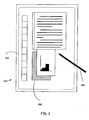
- Figure 2 shows a tablet personal computing (PC) environment in which one or more embodiments of the present invention may be implemented.
- PC personal computing
- Figure 3 shows an example of a graphical object usable in one or more embodiments of the present invention.
- Figure 4 shows an example highlighted graphical object according to one embodiment of the present invention.
- Figure 5 shows a close-up view of a portion of the highlighted graphical object shown in Fig. 4, according to one embodiment of the present invention.
- Figure 6 shows a close-up view of a portion of the highlighted graphical object shown in Fig. 4, according to another embodiment of the present invention.
- Figure 7 shows a close-up view of a portion of the highlighted graphical object shown in Fig. 4, according to yet another embodiment of the present invention.
- Figure 8 shows a highlighted graphical object according to a further embodiment of the present invention.
- Figures 9a-9b show alternate embodiments of moving graphical objects according to further embodiments of the present invention.
- Figure 10 shows an example of a graphical object to be highlighted according to aspects of the present invention.
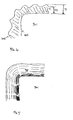
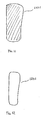
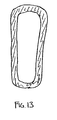
- Figures 11-13 show example steps in the creation of a highlighted graphical object according to one embodiment of the present invention.
- Figures 14-15 show example steps in the creation of a highlighted graphical object according to one embodiment of the present invention.
- Figures 16-17 show an example of highlighted text in the prior art.
- Figure 18 shows an example graphical object.
- Figures 19a-b show an example of a highlighted line in the prior art.
- Figures 20a-b are photographic examples of one embodiment of the present invention.
- Figures 21a-b are photographic examples of another embodiment of the present invention.
- FIG. 1 illustrates a schematic diagram of a conventional general-purpose digital computing environment that can be used to implement various aspects of the present invention.
- a computer 100 includes a processing unit 110, a system memory 120, and a system bus 130 that couples various system components including the system memory to the processing unit 110.
- the system bus 130 may be any of several types of bus structures including a memory bus or memory controller, a peripheral bus, and a local bus using any of a variety of bus architectures.
- the system memory 120 includes read only memory (ROM) 140 and random access memory (RAM) 150.
- a basic input/output system 160 (BIOS), containing the basic routines that help to transfer information between elements within the computer 100, such as during start-up, is stored in the ROM 140.
- the computer 100 also includes a hard disk drive 170 for reading from and writing to a hard disk (not shown), a magnetic disk drive 180 for reading from or writing to a removable magnetic disk 190, and an optical disk drive 191 for reading from or writing to a removable optical disk 192 such as a CD ROM or other optical media.
- the hard disk drive 170, magnetic disk drive 180, and optical disk drive 191 are connected to the system bus 130 by a hard disk drive interface 192, a magnetic disk drive interface 193, and an optical disk drive interface 194, respectively.
- the drives and their associated computer-readable media provide nonvolatile storage of computer readable instructions, data structures, program modules and other data for the personal computer 100. It will be appreciated by those skilled in the art that other types of computer readable media that can store data that is accessible by a computer, such as magnetic cassettes, flash memory cards, digital video disks, Bernoulli cartridges, random access memories (RAMs), read only memories (ROMs), and the like, may also be used in the example operating environment.
- RAMs random access memories
- ROMs read only memories
- a number of program modules can be stored on the hard disk drive 170, magnetic disk 190, optical disk 192, ROM 140 or RAM 150, including an operating system 195, one or more application programs 196, other program modules 197, and program data 198.
- a user can enter commands and information into the computer 100 through input devices such as a keyboard 101 and pointing device 102.
- Other input devices may include a microphone, joystick, game pad, satellite dish, scanner or the like.
- These and other input devices are often connected to the processing unit 110 through a serial port interface 106 that is coupled to the system bus, but may be connected by other interfaces, such as a parallel port, game port or a universal serial bus (USB).
- USB universal serial bus
- these devices may be coupled directly to the system bus 130 via an appropriate interface (not shown).
- a monitor 107 or other type of display device is also connected to the system bus 130 via an interface, such as a video adapter 108.
- personal computers typically include other peripheral output devices (not shown), such as speakers and printers.
- a pen digitizer 165 and accompanying pen or stylus 166 are provided in order to digitally capture freehand input.
- the pen digitizer 165 may be coupled to the processing unit 110 via a serial port, parallel port or other interface and the system bus 130 as known in the art.
- the digitizer 165 is shown apart from the monitor 107, it is preferred that the usable input area of the digitizer 165 be co-extensive with the display area of the monitor 107. Further still, the digitizer 165 may be integrated in the monitor 107, or may exist as a separate device overlaying or otherwise appended to the monitor 107.
- the computer 100 can operate in a networked environment using logical connections to one or more remote computers, such as a remote computer 109.
- the remote computer 109 can be a server, a router, a network PC, a peer device or other common network node, and typically includes many or all of the elements described above relative to the computer 100, although only a memory storage device 111 has been illustrated in FIG. 1.
- the logical connections depicted in FIG. 1 include a local area network (LAN) 112 and a wide area network (WAN) 113.
- LAN local area network
- WAN wide area network
- the computer 100 When used in a LAN networking environment, the computer 100 is connected to the local network 112 through a network interface or adapter 114. When used in a WAN networking environment, the personal computer 100 typically includes a modem 115 or other means for establishing a communications over the wide area network 113, such as the Internet.
- the modem 115 which may be internal or external, is connected to the system bus 130 via the serial port interface 106.
- program modules depicted relative to the personal computer 100, or portions thereof, may be stored in the remote memory storage device.
- network connections shown are examples and other techniques for establishing a communications link between the computers can be used.
- the existence of any of various well-known protocols such as TCP/IP, Ethernet, FTP, HTTP and the like is presumed, and the system can be operated in a client-server configuration to permit a user to retrieve web pages from a web-based server.
- Any of various conventional web browsers can be used to display and manipulate data on web pages.
- FIG. 1 environment shows an example environment, it will be understood that other computing environments may also be used.
- one or more embodiments of the present invention may use an environment having fewer than all of the various aspects shown in FIG. 1 and described above, and these aspects may appear in various combinations and subcombinations that will be apparent to one of ordinary skill.
- FIG. 2 illustrates a tablet personal computer (PC) 201 that can be used in accordance with various aspects of the present invention. Any or all of the features, subsystems, and functions in the system of Figure 1 can be included in the computer of Figure 2.
- Tablet PC 201 includes a large display surface 202, e.g., a digitizing flat panel display, preferably, a liquid crystal display (LCD) screen, on which a plurality of windows 203 is displayed.
- a user can select, highlight, and write on the digitizing display area.
- suitable digitizing display panels include electromagnetic pen digitizers, such as the Mutoh or Wacom pen digitizers. Other types of pen digitizers, e.g., optical digitizers, may also be used.
- Tablet PC 201 interprets marks made using stylus 204 in order to manipulate data, enter text, and execute conventional computer application tasks such as spreadsheets, word processing programs, and the like.
- a stylus could be equipped with buttons or other features to augment its selection capabilities.
- a stylus could be implemented as a "pencil” or “pen”, in which one end constitutes a writing portion and the other end constitutes an "eraser” end, and which, when moved across the display, indicates portions of the display are to be erased.
- Other types of input devices such as a mouse, trackball, or the like could be used.
- a user's own finger could be used for selecting or indicating portions of the displayed image on a touch-sensitive or proximity-sensitive display. Consequently, the term "user input device”, as used herein, is intended to have a broad definition and encompasses many variations on well-known input devices.
- Figure 3 shows an example of such a graphical object.
- the graphical object 300 is a handwritten version of the letter 'H' that, for example, is captured as digitized ink using a pen-based computer and its stylus.
- Other types of graphical objects include graphical icons, images, symbols, menus, prompts, and text.
- the body 301 of graphical object 300 may be drawn, or rendered, using any color or pattern value (e.g., hatched, shaded, a series of colors, etc.), and may be drawn on a background of a different color or pattern.
- the background 302 is a simple solid white background, but any other color and/or pattern may be used as the background 302.
- the background 302 may also be comprised of one or more other graphical objects.
- the background may include a series of parallel horizontal (or vertical) lines to assist the user in keeping handwritten text in line.
- the object need not be constrained to such lines, however, and may simply overlap 1, 2, 3 or more of them.
- the background may also include various other objects, such as text, images, drawings, handwriting, etc.
- the graphical object 300 may become highlighted to represent that it has been selected, or to otherwise draw attention to it. This may occur in any number of ways. For example, in a pen-based computing device, the user may position the stylus over the displayed graphical object to select the object. The user may move a pointer over the graphical object to select it, and may also press a button to select it. Any other known method for selecting a graphical object in a GUI will also suffice.
- the body 301 may have its color value changed to a transparent value, such that the background 302 becomes visible in the area previously occupied by the body 301.
- the highlighted graphical object may also have an outline, or "halo" 401, of additional color and/or pattern drawn around its periphery, surrounding the original body 301 of the graphical object.
- a graphical object in a first color/pattern (e.g., red) on a background of a second color/pattern (e.g., black striped) will, upon selection, be changed in appearance to have a halo in the first color/pattern (i.e., red), and a body in the second color/pattern (i.e., black striped) due to its transparency.
- the body 301 of the graphical object may have its color changed to a predetermined color, such as white, rather than a transparent color. The use of a predetermined color may advantageously simplify the processing required to render the highlighted graphical object.
- Fig. 5 shows a close-up view taken from area A-A shown in Fig. 4.
- the halo may be of a predetermined thickness (T), such as a certain number of pixels (e.g., 8, 10, 12, 15, 20, etc. pixels) or a predetermined distance (e.g., 1/16th of an inch, 1/8th of an inch, 1/4 of an inch, etc.), and appears in the original color of the graphical object.
- T a predetermined thickness
- the outer contour 502 of the halo 401 may follow the outer contour 501 of the graphical object 301.
- the contour 502 of the halo 401 may follow the outer contour 501 of the object 301 exactly, although a slight variation may occur due to the thickness of the halo 401.
- the selected graphical object will more closely resemble the original graphical object.
- the halo may have a varying thickness to give the selected object a more distinguished appearance.
- the thickness of the halo may simply vary to give the highlighted graphical object a glowing appearance.
- the variation may be periodic between two or more thicknesses (T1 and T2) (e.g., varying between 10 and 15 pixels every linear inch), or alternatively, may randomly vary among two or more thicknesses.
- the halo may also vary its color and/or pattern value.
- the halo color and/or pattern may be darker near the outer edges of the graphical object body 301, and become lighter near the outer edges of the halo 401.
- the color/pattern may be a lighter version of the same color (e.g. light green becoming green, grey becoming black, etc.), or of the pattern (e.g., less concentrated stripes and/or shading, etc.).
- This variation in the halo color helps give the highlighted graphical object a glowing appearance.
- Other variations may also be used.
- the color and/or pattern may become darker towards the outer edge 502 of the halo, or may vary in darkness throughout. The process by which an example halo may be generated and rendered for display will be described further below with respect to Figs. 10-15.
- some embodiments of the present invention allow the user to select the graphical object by selecting its halo.
- a pen-based computing device may allow users to select graphical objects by placing the stylus on or over the highlighted graphical object. Similar selections may be made using a mouse that moves an onscreen pointer, pressing a sequence of keys on a keyboard, or any other form of GUI interaction.
- graphical objects having a thin appearance e.g., a single hand-drawn stroke or line
- halos described above One advantage offered by some embodiments of the halos described above is apparent in situations where multiple graphical objects appear on the display screen, and overlap one another. If one of these graphical objects is selected, while the other is not, the transparent, or "hollow,” body of the selected graphical object, together with its halo, clearly set the object apart from the other unselected graphical object(s).
- the highlighted graphical object may also be surrounded by a bounding box.
- Figure 8 shows an example of a highlighted graphical object having a rectangular bounding box 801.
- the bounding box 801 may be defined such that it is a rectangular shape whose dimensions depend on the size of the graphical object.
- the borders of the box 801 are horizontal and vertical, and are located a predetermined distance (d1) to the left, right, above and below the graphical object.
- the distance (d1) is a set number of pixels, such as 8, 10, 12, 15, or 20.
- the borders shown in Fig. 8 are rendered using a dashed line, but any other line type and/or color may be used.
- the bounding box 801 need not be rectangular, and need not be a box, at all.
- the bounding box may actually be implemented as any other shape, such as a circle, oval, diamond, etc. to surround the graphical object being highlighted.
- the bounding box 801 may include one or more selection handles 802a,b that may be used to interact with the object for further handling, such as moving and/or resizing the object.
- Selection handles 802a may be located at the corners of the bounding box 801, and/or at other locations 802b along the borders of the box. By selecting one of these handles (e.g., using a mouse-controlled pointer, stylus, or any other GUI selection method), the user may resize the graphical object, and/or select the graphical object for further processing/editing.
- the bounding box border distance (d1) is configured to be of sufficient size such that the selection handles do not overlap or obscure any portion of the highlighted graphical object.
- the user may move a highlighted graphical object through various portions of the GUI.
- This movement may be made, for example, by the user selecting the graphical object in a pen-based computing system by placing a stylus on the graphical object, pressing a button on the stylus to select the graphical object, and then moving the stylus across a display screen to the desired new location.
- some embodiments of the present invention may display a moving version of the graphical object at a location corresponding to the user's device. In this manner, the user is given feedback regarding the movement he/she is carrying out, as well as the system's acknowledgement that the move operation has begun.
- the moving version of the graphical object may appear as a simple outline of the object, as shown in Fig. 9a, to assist the user in determining placement of the graphical object.
- the outline may be of any line type and/or color, and in some embodiments, is a thin dotted line. Using a simple dotted outline as the moving version allows the user to see background object(s) during the movement process.
- the moving version may alternatively appear as a bounding box with a pointer or cursor, as shown in Fig. 9b.
- the dimensions of the bounding box are the minimum dimensions necessary to enclose the graphical object. Using these minimum dimensions helps convey to the user the amount of space needed by the object. Alternatively, the dimensions of the box may be greater than the minimum. Using a simple bounding box may simplify the processing required for rendering the box during the movement process, and the presence of the cursor may help make clear that the object is being moved. Alternative embodiments of this moving version may simply have the bounding box, without the cursor.
- the moving version of the graphical object may simply be a copy of the graphical object rendered in a different color and/or pattern, such as using a lighter shade of the color, or a fainter version of the color that allows more transparency.
- a lighter or fainter color for the moving version of the graphical object, the user is provided with a clear indication of what will be obscured upon repositioning of the object.
- the moving versions described above may be rendered with its own bounding box and/or selection handles, as described above, to further indicate that a movement process has begun.
- the GUI may include several distinct areas in which different color contrasts are used.
- a GUI may have a first area in which black graphical objects appear against a white background, and a second area in which red graphical objects appear against a green background.
- a graphical object originally appearing in black ink may be replaced with a transparent body and a black halo.
- the user may move this object from the first area to the second area.
- the color of the highlighted graphical object's body and halo remain the same. In this manner, any meaning associated with the color of the underlying graphical object is preserved in the new GUI area.
- the highlighted graphical object's halo may change in color to that of the second area (in this example, red).
- Figures 10-15 depict example processes that may be used to generate and render an example highlighted graphical object according to one or more of the embodiments described above.
- Figure 10 depicts an example graphical object 1000 that may be highlighted.
- the object may be of any type of onscreen image, and one example would be a stroke of handwritten "ink" drawn by the user using a stylus and a touch-sensitive display.
- the stroke itself may follow a center line 1001, and may vary in thickness or width. This variation may arise from a variety of causes, such as the user varying the pressure placed upon the stylus while drawing the stroke.
- Figures 11-13 depict example steps that may result in a graphical halo such as the one shown in Fig. 5.
- the computer display system may first generate an enlarged version 1101 of the original graphical object, as shown in Fig. 11.
- the enlarged version 1101 may be of the same color as the original graphical object, and have its width and/or height increased by a predetermined size, such as 0.125 inches, 10 pixels, etc., or by a predetermined percentage, such as 5%, 10%, etc.
- a predetermined size such as 0.125 inches, 10 pixels, etc.
- a predetermined percentage such as 5%, 10%, etc.
- Increasing the dimensions by a predetermined amount advantageously allows consistency in the visual appearance of highlighted graphical objects.
- increasing the dimensions by a percentage may allow for a more dynamic visual experience.
- a graphical object comprised of lines may be enlarged by having its lines widened by the predetermined amount.
- the enlarged version 1101 in Fig. 11 has been slightly increased in both height and width.
- the computer display system may generate the enlarged version 1101 in an internal memory or display buffer, and need not actually display or render the enlarged version on screen immediately.
- the computer display system may also generate another copy 1201 of the original graphical object 1000, where the copy 1201 has the same dimensions as the original object.
- the copy 1201 may be assigned a color value that is the background color value of the area on which the original object was displayed.
- the copy 1201 may then be overlaid upon the enlarged version 1101, resulting in the highlighted graphical object shown in Fig. 13.
- the enlarged version 1101 and copy 1201 need not be displayed onscreen prior to this "overlaying," and may simply be constructed in a memory or video buffer of the system.
- the color value of the copy 1201 will be such that background images, text, and/or objects may be visible.
- the copy 1201 may be assigned this transparency color value, and when this copy 1201 is overlaid upon the enlarged version, the interior of the enlarged version becomes transparent in color, allowing background images to appear. This effect may be achieved even in systems that do not directly support the use of such transparency values.
- the copy 1201 may have the appearance of the graphical image, text, etc. that would have appeared directly behind the original object 1001.
- the copy 1201 may be assigned a predetermined color, such as white, to simplify the processing required to generate the halo.
- a predetermined color such as white
- Using the background minimizes the amount of visual real estate that is obscured by the halo, while using a predetermined color simplifies the processing involved.
- One additional advantage to allowing the background pattern to show lies in the readability of text that already has another highlighting (such as a yellow highlight) associated with it. If the text had already been highlighted, then allowing this highlighting to show through the hollow body of the halo helps preserve the meaning associated with that highlighting. The user is still able to see that the selected text had the highlight associated with it.
- a similar process of "overlaying" versions may be used to create the "glowing" effect of the halo shown in Fig. 7.
- multiple versions of the object may be created.
- one version 1401 is a copy, much like the copy 1201 shown in Fig. 12.
- One or more enlarged versions may also be created, where each version is of a slightly different size and color.
- version 1402 is slightly larger in dimension than version 1401, and is of the color of the original object.
- Another version 1403 is slightly larger than version 1402, and is of a slightly lighter color. This lighter color may be a lighter shade than that of version 1402.
- version 1403 may have the same color, but a greater transparency value, than version 1402. As with the Fig.
- the various versions shown in Fig. 14 may be overlaid upon one another to result in the highlighted object shown in Fig. 15.
- Fig. 15 example uses two enlarged versions
- other embodiments may use more enlarged versions, with slighter differences in size and/or color between them, to create a smoother "glowing" effect.
- four such enlarged versions are used.
- the original graphical object 1000 may have its width changed before the various copies and enlarged versions are created.
- the object 1000 may originally have a varying width, but for purposes of generating the halo, it may have its width changed to that of a constant value.
- This constant value may be predefined, or may simply be the average width calculated along various points of the center line 1001. Using such a constant width may simplify the processing required to generate the various copies and enlarged versions, and is particularly useful when the original graphical object was nearly of constant width to begin with (e.g., if the original graphical object was constructed using a linear stroke of a stylus).
- the various steps of "overlaying" described above may be achieved using a version of the object(s) stored in a memory or display buffer.
- the overlaying may be performed on a pixel-by-pixel basis by replacing the individual pixels of a portion of one image with those of another image.
- the graphical halo may be generated using the outer contour of the graphical object to define the contour that is to be followed by the halo.
- the computer system may calculate the path to be taken by the halo, and render just that path on the screen to create the halo effect.
- the halo may be rendered by tracing a single line around the contour. In such an embodiment, no processing is necessary for the "hollow" portion of the halo, but greater processing is needed to trace the path.
- the halo outline may be anti-aliased for improved resolution.
- Figures 20a-b are photographic images of one example embodiment.
- a handwritten word "highlight” 2001 is shown having a highlighting 2002.
- Highlighting 2002 may resemble the traditional highlighting generated using a hand-held highlighter marker.
- Figure 20b shows an example in which the highlighting 2002 has been selected by the user, and exhibits a hollow selection feedback described above. In the depicted example, there is also a bounding box 2003 having selection handles 2004.
- Figures 21a-b are photographic images of another example embodiment.
- the stroke 2101 has been selected, and exhibits a hollow selection feedback described above.
- This depicted example also includes a bounding box 2102 having selection handles 2103.
- the interior of the bounding box 2102 may be transparent, to permit the background to show through.
Landscapes
- Engineering & Computer Science (AREA)
- Theoretical Computer Science (AREA)
- General Engineering & Computer Science (AREA)
- Physics & Mathematics (AREA)
- General Physics & Mathematics (AREA)
- Human Computer Interaction (AREA)
- User Interface Of Digital Computer (AREA)
- Processing Or Creating Images (AREA)
- Digital Computer Display Output (AREA)
Applications Claiming Priority (2)
| Application Number | Priority Date | Filing Date | Title |
|---|---|---|---|
| US144256 | 1998-08-31 | ||
| US10/144,256 US20030214539A1 (en) | 2002-05-14 | 2002-05-14 | Method and apparatus for hollow selection feedback |
Publications (2)
| Publication Number | Publication Date |
|---|---|
| EP1363185A2 true EP1363185A2 (de) | 2003-11-19 |
| EP1363185A3 EP1363185A3 (de) | 2007-12-05 |
Family
ID=29269721
Family Applications (1)
| Application Number | Title | Priority Date | Filing Date |
|---|---|---|---|
| EP03008066A Withdrawn EP1363185A3 (de) | 2002-05-14 | 2003-04-14 | Verfahren und Vorrichtung einer Vertiefung zur Auswahlsrückkopplung |
Country Status (2)
| Country | Link |
|---|---|
| US (2) | US20030214539A1 (de) |
| EP (1) | EP1363185A3 (de) |
Cited By (2)
| Publication number | Priority date | Publication date | Assignee | Title |
|---|---|---|---|---|
| WO2006053266A3 (en) * | 2004-11-10 | 2007-02-01 | Apple Computer | Highlighting items for search results |
| WO2007089461A1 (en) | 2006-01-31 | 2007-08-09 | Microsoft Corporation | Semi-transparent highlighting of selected objects in electronic documents |
Families Citing this family (27)
| Publication number | Priority date | Publication date | Assignee | Title |
|---|---|---|---|---|
| US7432939B1 (en) * | 2002-07-10 | 2008-10-07 | Apple Inc. | Method and apparatus for displaying pixel images for a graphical user interface |
| US7137077B2 (en) * | 2002-07-30 | 2006-11-14 | Microsoft Corporation | Freeform encounter selection tool |
| US20040075699A1 (en) * | 2002-10-04 | 2004-04-22 | Creo Inc. | Method and apparatus for highlighting graphical objects |
| US7057628B2 (en) * | 2003-10-15 | 2006-06-06 | Anthony Bruce Crawford | Method for locating white space to support the automated creation of computer-based drawings that are virtually free of graphics and text overwrites |
| US9213714B1 (en) * | 2004-06-22 | 2015-12-15 | Apple Inc. | Indicating hierarchy in a computer system with a graphical user interface |
| US7873916B1 (en) * | 2004-06-22 | 2011-01-18 | Apple Inc. | Color labeling in a graphical user interface |
| US20060005151A1 (en) * | 2004-07-02 | 2006-01-05 | Adobe Systems | Graphical interface for adjustment of text selections |
| US7868888B2 (en) * | 2006-02-10 | 2011-01-11 | Adobe Systems Incorporated | Course grid aligned counters |
| US8739068B2 (en) | 2007-06-15 | 2014-05-27 | Microsoft Corporation | Dynamic user interface for in-diagram shape selection |
| US8762871B2 (en) * | 2008-02-03 | 2014-06-24 | Microsoft Corporation | Dynamic preview of diagram elements to be inserted into a diagram |
| EP2335450A1 (de) * | 2008-10-08 | 2011-06-22 | Research In Motion Limited | Änderung des erscheinungsbildes einer beweglichen positionsmarkierung auf einem anzeigebildschirm einer tragbaren elektronischen kommunikationsvorrichtung |
| US8490026B2 (en) * | 2008-10-27 | 2013-07-16 | Microsoft Corporation | Painting user controls |
| TWM385730U (en) * | 2010-02-02 | 2010-08-01 | Sunrex Technology Corp | Computer input device with a marco function configuration |
| US8782556B2 (en) * | 2010-02-12 | 2014-07-15 | Microsoft Corporation | User-centric soft keyboard predictive technologies |
| KR101705872B1 (ko) * | 2010-09-08 | 2017-02-10 | 삼성전자주식회사 | 모바일 디바이스의 화면상의 영역 선택 방법 및 장치 |
| US20120102401A1 (en) * | 2010-10-25 | 2012-04-26 | Nokia Corporation | Method and apparatus for providing text selection |
| US10169909B2 (en) * | 2014-08-07 | 2019-01-01 | Pixar | Generating a volumetric projection for an object |
| CN105808083B (zh) * | 2014-12-30 | 2022-02-11 | 鸿合科技股份有限公司 | 一种显示方法与装置 |
| US10860788B2 (en) | 2016-09-23 | 2020-12-08 | Apple Inc. | Device, method, and graphical user interface for annotating text |
| EP3593236B1 (de) | 2017-06-02 | 2024-10-23 | Apple Inc. | Vorrichtung, verfahren und grafische benutzeroberfläche zum annotieren von inhalt |
| US10929208B1 (en) * | 2018-05-09 | 2021-02-23 | Accusoft Corporation | Methods and apparatus for copying a selected browser region to a clipboard as an image |
| US12340034B2 (en) | 2018-06-01 | 2025-06-24 | Apple Inc. | Devices, methods, and graphical user interfaces for an electronic device interacting with a stylus |
| US12093523B2 (en) | 2019-05-06 | 2024-09-17 | Apple Inc. | Handwriting entry on an electronic device |
| US11656758B2 (en) * | 2020-05-11 | 2023-05-23 | Apple Inc. | Interacting with handwritten content on an electronic device |
| JP2021197024A (ja) * | 2020-06-17 | 2021-12-27 | 株式会社リコー | 表示装置、表示方法及びプログラム |
| US11978152B2 (en) * | 2021-06-08 | 2024-05-07 | Roblox Corporation | Computer-assisted graphical development tools |
| WO2023220165A1 (en) | 2022-05-10 | 2023-11-16 | Apple Inc. | Interactions between an input device and an electronic device |
Citations (5)
| Publication number | Priority date | Publication date | Assignee | Title |
|---|---|---|---|---|
| US5682439A (en) * | 1995-08-07 | 1997-10-28 | Apple Computer, Inc. | Boxed input correction system and method for pen based computer systems |
| US5757383A (en) * | 1996-05-10 | 1998-05-26 | Apple Computer, Inc. | Method and system for highlighting typography along a geometric path |
| US6057858A (en) * | 1996-08-07 | 2000-05-02 | Desrosiers; John J. | Multiple media fonts |
| US6212577B1 (en) * | 1993-03-03 | 2001-04-03 | Apple Computer, Inc. | Method and apparatus for improved interaction with an application program according to data types and actions performed by the application program |
| US7873916B1 (en) * | 2004-06-22 | 2011-01-18 | Apple Inc. | Color labeling in a graphical user interface |
Family Cites Families (49)
| Publication number | Priority date | Publication date | Assignee | Title |
|---|---|---|---|---|
| US4570182A (en) * | 1983-11-18 | 1986-02-11 | Sperry Corporation | Halo generator for CRT display symbols |
| US4698666A (en) * | 1985-07-12 | 1987-10-06 | The Grass Valley Group, Inc. | Video key glow and border generator |
| CA2040681A1 (en) * | 1990-04-26 | 1991-10-27 | Alan H. Trist | Image editing system |
| US5442742A (en) * | 1990-12-21 | 1995-08-15 | Apple Computer, Inc. | Method and apparatus for the manipulation of text on a computer display screen |
| US5500934A (en) * | 1991-09-04 | 1996-03-19 | International Business Machines Corporation | Display and control system for configuring and monitoring a complex system |
| US5339387A (en) * | 1991-10-24 | 1994-08-16 | Abekas Video Systems, Inc. | Planar color gradients constructed as an arbitrary function of a distance function from an arbitrary 2-D curvilinear function |
| CA2080209A1 (en) * | 1992-01-10 | 1993-07-11 | Eric Allen Brewer | Spatially organized computer display system |
| US5539427A (en) * | 1992-02-10 | 1996-07-23 | Compaq Computer Corporation | Graphic indexing system |
| FR2690031A1 (fr) * | 1992-04-14 | 1993-10-15 | Philips Electronique Lab | Dispositif de segmentation d'images. |
| US5410331A (en) * | 1992-05-20 | 1995-04-25 | Carmex, Inc. | Process for generating and/or using a look-up table |
| US5666139A (en) * | 1992-10-15 | 1997-09-09 | Advanced Pen Technologies, Inc. | Pen-based computer copy editing apparatus and method for manuscripts |
| US5754178A (en) * | 1993-03-03 | 1998-05-19 | Apple Computer, Inc. | Method and apparatus for improved feedback during manipulation of data on a computer controlled display system |
| JPH07146931A (ja) * | 1993-03-08 | 1995-06-06 | Canon Inf Syst Res Australia Pty Ltd | 画像創成方法 |
| WO1994027229A1 (en) * | 1993-05-10 | 1994-11-24 | Apple Computer, Inc. | Computer-human interface system which manipulates parts between a desktop and a document |
| US6535897B1 (en) * | 1993-05-20 | 2003-03-18 | Microsoft Corporation | System and methods for spacing, storing and recognizing electronic representations of handwriting printing and drawings |
| CA2124505C (en) * | 1993-07-21 | 2000-01-04 | William A. S. Buxton | User interface having simultaneously movable tools and cursor |
| US5577170A (en) * | 1993-12-23 | 1996-11-19 | Adobe Systems, Incorporated | Generation of typefaces on high resolution output devices |
| US6014138A (en) * | 1994-01-21 | 2000-01-11 | Inprise Corporation | Development system with methods for improved visual programming with hierarchical object explorer |
| US5470182A (en) * | 1994-02-04 | 1995-11-28 | Omation Corporation | Envelope opening machine |
| EP0758517B1 (de) * | 1994-04-28 | 2004-06-09 | BRITISH TELECOMMUNICATIONS public limited company | Dienstleistungssystem für kommunikationsnetzwerke |
| US5754187A (en) * | 1994-05-16 | 1998-05-19 | Agfa Division, Bayer Corporation | Method for data compression of digital data to produce a scaleable font database |
| JPH0816313A (ja) * | 1994-07-04 | 1996-01-19 | Sanyo Electric Co Ltd | 手書き入力方法及び装置 |
| US5621871A (en) * | 1994-08-31 | 1997-04-15 | Jaremko; Mark | Automated system and method for annotation using callouts |
| US5687331A (en) * | 1995-08-03 | 1997-11-11 | Microsoft Corporation | Method and system for displaying an animated focus item |
| US20020056136A1 (en) * | 1995-09-29 | 2002-05-09 | Wistendahl Douglass A. | System for converting existing TV content to interactive TV programs operated with a standard remote control and TV set-top box |
| US6496981B1 (en) * | 1997-09-19 | 2002-12-17 | Douglass A. Wistendahl | System for converting media content for interactive TV use |
| US5982381A (en) * | 1997-07-03 | 1999-11-09 | Microsoft Corporation | Method and apparatus for modifying a cutout image for compositing |
| US6077307A (en) * | 1997-10-31 | 2000-06-20 | Hewlett Packard Company | Forced conformance design-rule halos for computer aided design software |
| GB2332348A (en) * | 1997-12-09 | 1999-06-16 | Zyris Plc | Graphic image design |
| US6091505A (en) * | 1998-01-30 | 2000-07-18 | Apple Computer, Inc. | Method and system for achieving enhanced glyphs in a font |
| US6628666B1 (en) * | 1998-03-30 | 2003-09-30 | Genesys Telecomm Lab Inc | Managing bandwidth on demand for internet protocol messaging with capability for transforming telephony calls from one media type to another media type |
| US6054989A (en) * | 1998-09-14 | 2000-04-25 | Microsoft Corporation | Methods, apparatus and data structures for providing a user interface, which exploits spatial memory in three-dimensions, to objects and which provides spatialized audio |
| US6243093B1 (en) * | 1998-09-14 | 2001-06-05 | Microsoft Corporation | Methods, apparatus and data structures for providing a user interface, which exploits spatial memory in three-dimensions, to objects and which visually groups matching objects |
| US6337698B1 (en) * | 1998-11-20 | 2002-01-08 | Microsoft Corporation | Pen-based interface for a notepad computer |
| US6337689B1 (en) * | 1999-04-03 | 2002-01-08 | Hewlett-Packard Company | Adaptive buffering of computer graphics vertex commands |
| US6476834B1 (en) * | 1999-05-28 | 2002-11-05 | International Business Machines Corporation | Dynamic creation of selectable items on surfaces |
| US7278115B1 (en) * | 1999-06-18 | 2007-10-02 | Microsoft Corporation | Methods, apparatus and data structures for providing a user interface to objects, the user interface exploiting spatial memory and visually indicating at least one object parameter |
| US6633309B2 (en) * | 1999-08-16 | 2003-10-14 | University Of Washington | Interactive video object processing environment having concurrently active subordinate windows |
| US7428705B2 (en) * | 1999-11-30 | 2008-09-23 | Maxamine International Pyt Ltd | Web map tool |
| US7367042B1 (en) * | 2000-02-29 | 2008-04-29 | Goldpocket Interactive, Inc. | Method and apparatus for hyperlinking in a television broadcast |
| US6948134B2 (en) * | 2000-07-21 | 2005-09-20 | Microsoft Corporation | Integrated method for creating a refreshable Web Query |
| US6381519B1 (en) * | 2000-09-19 | 2002-04-30 | Honeywell International Inc. | Cursor management on a multiple display electronic flight instrumentation system |
| US6684379B2 (en) * | 2000-10-18 | 2004-01-27 | Chipworks | Design analysis workstation for analyzing integrated circuits |
| US20020126990A1 (en) * | 2000-10-24 | 2002-09-12 | Gary Rasmussen | Creating on content enhancements |
| WO2002050657A1 (en) * | 2000-12-19 | 2002-06-27 | Coolernet, Inc. | System and method for multimedia authoring and playback |
| US20040039934A1 (en) * | 2000-12-19 | 2004-02-26 | Land Michael Z. | System and method for multimedia authoring and playback |
| US7054482B2 (en) * | 2001-09-28 | 2006-05-30 | Arcsoft, Inc. | Smart masking tool for image processing |
| US7174510B2 (en) * | 2001-10-20 | 2007-02-06 | Hal Christopher Salter | Interactive game providing instruction in musical notation and in learning an instrument |
| US6968511B1 (en) * | 2002-03-07 | 2005-11-22 | Microsoft Corporation | Graphical user interface, data structure and associated method for cluster-based document management |
-
2002
- 2002-05-14 US US10/144,256 patent/US20030214539A1/en not_active Abandoned
-
2003
- 2003-04-14 EP EP03008066A patent/EP1363185A3/de not_active Withdrawn
-
2005
- 2005-03-01 US US11/067,949 patent/US7870501B2/en not_active Expired - Fee Related
Patent Citations (5)
| Publication number | Priority date | Publication date | Assignee | Title |
|---|---|---|---|---|
| US6212577B1 (en) * | 1993-03-03 | 2001-04-03 | Apple Computer, Inc. | Method and apparatus for improved interaction with an application program according to data types and actions performed by the application program |
| US5682439A (en) * | 1995-08-07 | 1997-10-28 | Apple Computer, Inc. | Boxed input correction system and method for pen based computer systems |
| US5757383A (en) * | 1996-05-10 | 1998-05-26 | Apple Computer, Inc. | Method and system for highlighting typography along a geometric path |
| US6057858A (en) * | 1996-08-07 | 2000-05-02 | Desrosiers; John J. | Multiple media fonts |
| US7873916B1 (en) * | 2004-06-22 | 2011-01-18 | Apple Inc. | Color labeling in a graphical user interface |
Cited By (17)
| Publication number | Priority date | Publication date | Assignee | Title |
|---|---|---|---|---|
| US8607162B2 (en) | 2004-11-10 | 2013-12-10 | Apple Inc. | Searching for commands and other elements of a user interface |
| US12182146B2 (en) | 2004-11-10 | 2024-12-31 | Apple Inc. | Highlighting icons for search results |
| US11500890B2 (en) | 2004-11-10 | 2022-11-15 | Apple Inc. | Highlighting icons for search results |
| US10635683B2 (en) | 2004-11-10 | 2020-04-28 | Apple Inc. | Highlighting items for search results |
| WO2006053266A3 (en) * | 2004-11-10 | 2007-02-01 | Apple Computer | Highlighting items for search results |
| US9659069B2 (en) | 2004-11-10 | 2017-05-23 | Apple Inc. | Highlighting items for search results |
| US7979796B2 (en) | 2004-11-10 | 2011-07-12 | Apple Inc. | Searching for commands and other elements of a user interface |
| US8677274B2 (en) | 2004-11-10 | 2014-03-18 | Apple Inc. | Highlighting items for search results |
| EP1994475A4 (de) * | 2006-01-31 | 2010-08-04 | Microsoft Corp | Halbtransparente hervorhebung ausgewählter objekte in elektronischen dokumenten |
| KR101331330B1 (ko) * | 2006-01-31 | 2013-11-20 | 마이크로소프트 코포레이션 | 전자 문서 내의 선택된 객체의 하이라이팅 방법 및 컴퓨터판독 가능 매체 |
| AU2007210250B2 (en) * | 2006-01-31 | 2011-07-28 | Microsoft Technology Licensing, Llc | Semi-transparent highlighting of selected objects in electronic documents |
| RU2424571C2 (ru) * | 2006-01-31 | 2011-07-20 | Майкрософт Корпорейшн | Полупрозрачное подсвечивание выбранных объектов в электронных документах |
| CN101375277B (zh) * | 2006-01-31 | 2011-04-06 | 微软公司 | 电子文档内所选对象的半透明突出显示 |
| NO341368B1 (no) * | 2006-01-31 | 2017-10-23 | Microsoft Technology Licensing Llc | Halv-transparent utheving av utvalgte objekter i elektroniske dokumenter |
| JP2009525535A (ja) * | 2006-01-31 | 2009-07-09 | マイクロソフト コーポレーション | 電子文書内の選択されたオブジェクトの半透明なハイライト方法 |
| US7479968B2 (en) | 2006-01-31 | 2009-01-20 | Microsoft Corporation | Semi-transparent highlighting of selected objects in electronic documents |
| WO2007089461A1 (en) | 2006-01-31 | 2007-08-09 | Microsoft Corporation | Semi-transparent highlighting of selected objects in electronic documents |
Also Published As
| Publication number | Publication date |
|---|---|
| US7870501B2 (en) | 2011-01-11 |
| US20030214539A1 (en) | 2003-11-20 |
| US20050149882A1 (en) | 2005-07-07 |
| EP1363185A3 (de) | 2007-12-05 |
Similar Documents
| Publication | Publication Date | Title |
|---|---|---|
| US7870501B2 (en) | Method for hollow selection feedback | |
| US7428711B2 (en) | Glow highlighting as an ink attribute | |
| US7190379B2 (en) | Method for resizing and moving an object on a computer screen | |
| US8166388B2 (en) | Overlaying electronic ink | |
| US8132125B2 (en) | Freeform encounter selection tool | |
| CA2124604C (en) | Method and apparatus for operating on an object-based model data structure to produce a second image in the spatial context of a first image | |
| JP4637455B2 (ja) | ユーザインタフェースの利用方法並びにコンピュータで使用可能な媒体を含む製品 | |
| US5652851A (en) | User interface technique for producing a second image in the spatial context of a first image using a model-based operation | |
| US7028256B2 (en) | Adding white space to a document generating adjusted page sizing | |
| US20050015731A1 (en) | Handling data across different portions or regions of a desktop | |
| US20040257346A1 (en) | Content selection and handling | |
| US9128919B2 (en) | Smart space insertion | |
| US20070174782A1 (en) | Smart icon placement across desktop size changes | |
| JP5664164B2 (ja) | 電子情報ボード装置、情報表示方法、プログラム | |
| US20090091547A1 (en) | Information display device | |
| US20170344248A1 (en) | Image processing device, image processing system, and image processing method | |
| US7483017B2 (en) | Ink collection and rendering | |
| US7454699B2 (en) | Smart content insertion | |
| US20180189248A1 (en) | Automated data extraction from a chart | |
| US7296240B1 (en) | Document object membranes | |
| CN105786314A (zh) | 窗口调整方法及使用该方法的电子装置 | |
| JP2004185478A (ja) | イラスト作成プログラムと描線プログラム | |
| RU2365979C2 (ru) | Ввод и воспроизведение электронных чернил | |
| HK1061586B (en) | Method for overlaying electronic ink on a document |
Legal Events
| Date | Code | Title | Description |
|---|---|---|---|
| PUAI | Public reference made under article 153(3) epc to a published international application that has entered the european phase |
Free format text: ORIGINAL CODE: 0009012 |
|
| AK | Designated contracting states |
Kind code of ref document: A2 Designated state(s): AT BE BG CH CY CZ DE DK EE ES FI FR GB GR HU IE IT LI LU MC NL PT RO SE SI SK TR |
|
| AX | Request for extension of the european patent |
Extension state: AL LT LV MK |
|
| 17P | Request for examination filed |
Effective date: 20070212 |
|
| PUAL | Search report despatched |
Free format text: ORIGINAL CODE: 0009013 |
|
| AK | Designated contracting states |
Kind code of ref document: A3 Designated state(s): AT BE BG CH CY CZ DE DK EE ES FI FR GB GR HU IE IT LI LU MC NL PT RO SE SI SK TR |
|
| AX | Request for extension of the european patent |
Extension state: AL LT LV MK |
|
| AKX | Designation fees paid |
Designated state(s): AT BE BG CH CY CZ DE DK EE ES FI FR GB GR HU IE IT LI LU MC NL PT RO SE SI SK TR |
|
| 17Q | First examination report despatched |
Effective date: 20101203 |
|
| RAP1 | Party data changed (applicant data changed or rights of an application transferred) |
Owner name: MICROSOFT TECHNOLOGY LICENSING, LLC |
|
| GRAP | Despatch of communication of intention to grant a patent |
Free format text: ORIGINAL CODE: EPIDOSNIGR1 |
|
| RIC1 | Information provided on ipc code assigned before grant |
Ipc: G06F 3/0481 20130101AFI20160408BHEP |
|
| INTG | Intention to grant announced |
Effective date: 20160429 |
|
| RIN1 | Information on inventor provided before grant (corrected) |
Inventor name: JARRETT, ROBERT J. Inventor name: DAVIS, SHAWNA Inventor name: JONES, DAVID F. Inventor name: BARKER, GUY Inventor name: IWEMA, MARIEKE Inventor name: DRESEVIC, BODIN |
|
| STAA | Information on the status of an ep patent application or granted ep patent |
Free format text: STATUS: THE APPLICATION IS DEEMED TO BE WITHDRAWN |
|
| 18D | Application deemed to be withdrawn |
Effective date: 20160910 |