EP1363392A2 - Gilbert-Zelle-Mischer - Google Patents
Gilbert-Zelle-Mischer Download PDFInfo
- Publication number
- EP1363392A2 EP1363392A2 EP03004967A EP03004967A EP1363392A2 EP 1363392 A2 EP1363392 A2 EP 1363392A2 EP 03004967 A EP03004967 A EP 03004967A EP 03004967 A EP03004967 A EP 03004967A EP 1363392 A2 EP1363392 A2 EP 1363392A2
- Authority
- EP
- European Patent Office
- Prior art keywords
- mixers
- amplifier
- gain
- mixer
- circuit
- Prior art date
- Legal status (The legal status is an assumption and is not a legal conclusion. Google has not performed a legal analysis and makes no representation as to the accuracy of the status listed.)
- Withdrawn
Links
Images





Classifications
-
- H—ELECTRICITY
- H03—ELECTRONIC CIRCUITRY
- H03D—DEMODULATION OR TRANSFERENCE OF MODULATION FROM ONE CARRIER TO ANOTHER
- H03D7/00—Transference of modulation from one carrier to another, e.g. frequency-changing
- H03D7/14—Balanced arrangements
- H03D7/1425—Balanced arrangements with transistors
- H03D7/1441—Balanced arrangements with transistors using field-effect transistors
-
- H—ELECTRICITY
- H03—ELECTRONIC CIRCUITRY
- H03D—DEMODULATION OR TRANSFERENCE OF MODULATION FROM ONE CARRIER TO ANOTHER
- H03D7/00—Transference of modulation from one carrier to another, e.g. frequency-changing
- H03D7/14—Balanced arrangements
- H03D7/1425—Balanced arrangements with transistors
- H03D7/1458—Double balanced arrangements, i.e. where both input signals are differential
-
- H—ELECTRICITY
- H03—ELECTRONIC CIRCUITRY
- H03D—DEMODULATION OR TRANSFERENCE OF MODULATION FROM ONE CARRIER TO ANOTHER
- H03D7/00—Transference of modulation from one carrier to another, e.g. frequency-changing
- H03D7/14—Balanced arrangements
- H03D7/1425—Balanced arrangements with transistors
- H03D7/1466—Passive mixer arrangements
-
- H—ELECTRICITY
- H03—ELECTRONIC CIRCUITRY
- H03D—DEMODULATION OR TRANSFERENCE OF MODULATION FROM ONE CARRIER TO ANOTHER
- H03D2200/00—Indexing scheme relating to details of demodulation or transference of modulation from one carrier to another covered by H03D
- H03D2200/0001—Circuit elements of demodulators
- H03D2200/0025—Gain control circuits
-
- H—ELECTRICITY
- H03—ELECTRONIC CIRCUITRY
- H03D—DEMODULATION OR TRANSFERENCE OF MODULATION FROM ONE CARRIER TO ANOTHER
- H03D2200/00—Indexing scheme relating to details of demodulation or transference of modulation from one carrier to another covered by H03D
- H03D2200/0041—Functional aspects of demodulators
- H03D2200/0084—Lowering the supply voltage and saving power
-
- H—ELECTRICITY
- H03—ELECTRONIC CIRCUITRY
- H03D—DEMODULATION OR TRANSFERENCE OF MODULATION FROM ONE CARRIER TO ANOTHER
- H03D2200/00—Indexing scheme relating to details of demodulation or transference of modulation from one carrier to another covered by H03D
- H03D2200/0041—Functional aspects of demodulators
- H03D2200/0088—Reduction of intermodulation, nonlinearities, adjacent channel interference; intercept points of harmonics or intermodulation products
Definitions
- the present invention relates generally to communications, and more specifically to modulation and demodulation systems.
- Frequency mixers are important building blocks in transceiver design since the dynamic range and noise/distortion performance of a transmitter/receiver is determined, and often limited, by the first up-down-conversion mixer. There are several types of mixer design used in the industry, probably one of the more popular being the Gilbert mixer.
- a Gilbert mixer In a Gilbert mixer an emitter-coupled transistor pair is used to switch the current path between the inner and outer transistors of a collector-cross-coupled quad; this switching creates a double-balanced mixing action.
- Gilbert mixers differ significantly from diode mixers.
- the Gilbert cell is an amplifier, so the mixer now has conversion gain rather than the approximately 7 dB loss of a passive mixer.
- the switching action of the mixer takes relatively little energy to initiate, so although the Integrated Circuit (IC) mixer must be DC biased, its total power budget is often less than that required for a passive mixer driven by a much higher-powered LO.
- the Gilbert cell is often less sensitive to loading, and doesn't require any bulky transformers, making it an extremely convenient device to use.
- the traditional Gilbert mixer has a structure which is based on the application of the well-known cascode structure (also known as a totem pole or tree structure), which, although providing a stable and approximately linear performance, has a disadvantage of requiring a relatively high voltage to operate.
- cascode structure also known as a totem pole or tree structure
- a dual mixer configuration which comprises two pairs of quadrature mixers and a Local Oscillator (LO) power divider thereby yielding two sequential steps of frequency conversion using two separate LO signals.
- the dual mixer is typically used in image rejection mixers.
- the quadrature LO required may be generated by any of the methods known to those skilled in the art.
- VLSI Very Large Scale Integration
- radio frequency circuitry is required to meet stringent performance specifications while operating from a low voltage supply.
- the folded Gilbert cell mixer is an application of current folding that allows Gilbert cell mixing operation at low voltages (below 1.8 volts).
- the invention alleviates the aforementioned disadvantages and other disadvantages, and provides the following advantages:
- the invention can be applied to both single stage and dual mixers to give low noise performance and Automatic Gain Control (AGC).
- AGC Automatic Gain Control
- devices become more sophisticated, and are able to measure their own performance in real-time, it is becoming practical to optimise their performance, if not during actual use, then at least during some part of the final factory testing.
- One such parameter is the linearity of the mixer.
- CMOS Complementary Metal Oxide Silicon
- the signals, local oscillators, and the various amplifiers and mixers being described operate in 'balanced' or differential mode, generally using a positive-going and complementary negative-going signal (or path as appropriate), not requiring or dependent on any ground reference.
- the local oscillator signals comprise a pair of sinusoidal signals bearing a quadrature relationship to one another, other types of the local oscillator signals are possible, as will be appreciated by those skilled in the art.
- Figure 1 illustrates a prior art traditional Gilbert cell multiplier or mixer circuit.
- the circuit receives a differential voltage, RF+, RF-, as the radio frequency (RF) input signal, and a differential voltage, LO1+, LO1-, as the local oscillator (LO) signal.
- the differential output voltage appears between the load resistors 180,182 in the active mixer portion of the circuit.
- the load resistors 180 and 182 have the same value.
- the circuit includes a number of Field Effect Transistors (FET) transistors, 110, 120, 130, 140, 150, and 160 which are normally biased to operate in the high gain saturation region.
- FET Field Effect Transistors
- the RF+ signal is applied to the gate of transistor 150, and the RF- signal is applied to the gate of transistor 160, these transistors 150, 160 being coupled as a differential pair, their sources being coupled together to ground, labelled GND.
- the sources of transistors 110 and 120 are coupled together as a differential pair whose common connection is coupled to the drain of transistor 150.
- the sources of transistors 130 and 140 are coupled together as a differential pair whose common connection is coupled to the drain of transistor 160.
- the gates of transistors 110 and 140 are controlled by the LO+ signal, and the gates of transistors 120 and 130 are controlled by the LO- signal.
- the conversion gain of the multiplier is increased as the value of the load resistors 180, 182 is increased.
- the value of the load resistors cannot merely be increased arbitrarily to any value because an increase in the resistance causes a significant DC voltage drop at the top of the cell. If only a small voltage remains at the drain of transistors 110, 120, 130 and 140, then there is insufficient voltage available to power the RF amplifier part of the circuit, transistors 150, 160. In particular, for applications where the power supply is typically set at approximately 2.7 volts to 3 volts, the drop in voltage due to large resistive values of 180 and 182 is unacceptable.
- Preferred embodiments of the invention are implemented as a modifications to a Gilbert mixer circuit to alleviate the disadvantages and problems introduced because of low voltage power supply typically found in low-power devices such as portable cellular phones. Generally, in these circumstances, the use of an active mixer results in poor linearity when using prior art designs.
- a preferred embodiment of the invention is next described with reference to a Gilbert mixer circuit as shown in Figure 2.
- the components labelled 110 to 190 perform the same functions as in Figure 1.
- the extra components are next described in detail, with particular reference to their effect on the operation of the Gilbert mixer circuit.
- a current injection circuit is introduced comprising a constant current source 270 and two resistors 284 and 286. This current injection circuit is arranged to provide the majority of current required by the RF amplifier transistors thereby requiring the active mixer switches to provide only a small proportion of the current required for the RF amplifier stage.
- the reduced contribution of current to the RF amplifier circuit results in less noise being referred to the inputs of the active mixer input transistors and also less noise being generated by the resistive load of the active mixer circuit, resulting in improved overall noise performance.
- the total current flowing through the RF amplifier transistors can be maintained at a level sufficient to ensure their operation at the required gain and linearity as further discussed below.
- the resistors 284, 286 forming part of the current injection source also affect the gain of the input transistors 150, 160 which form the RF amplifier or input stage of the mixer. As will be appreciated by those skilled in the art, decreasing the value of these resistors 284, 286 reduces the conversion gain of the overall mixer circuit. Similarly, increasing the value of the resistors increases the conversion gain. The value of the resistors 284, 286 must therefore be chosen with care to provide acceptable overall noise performance and overall conversion gain.
- the linearity of an active mixer is dependent on the biasing voltage of transistors.
- a simple voltage divider is used as the load of mixer.
- the optimum biasing must be found through simulation or other techniques. The bias voltage applied to each of the drains of the active mixer switches is thereby selected and fixed to that necessary for optimum linearity during design.
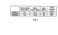
- Figure 3 is table showing the predicted performance parameters for a typical implementation using one preferred embodiment of the invention (Note: IIP3 - third-order Input Intercept Point- the theoretical input level at which the third-order two-tone distortion products are equal in power to the desired signals.) These figures are comparable to a more 'traditional design', but are achieved with lower voltage supply line in the preferred embodiment.
- the figure 4 shows a further preferred embodiment of the invention in which resistors which form part of the current injection source feeding the RF amplifier circuit are replaced by a pair of transistors 496, 498 acting as variable resistors.
- the components labelled 110 to 190 perform the same functions as in Figure 1.
- V agc, V agc' of the transistors 496, 498 By varying the gate bias voltages V agc, V agc' of the transistors 496, 498, the resistance of the transistors change and therefore the conversion gain is varied. As would be appreciated by one skilled in the art, this can be used as part of an AGC circuit for mixer.
- This preferred embodiment allows a designer the additional freedom of permitting changes in gain, noise performance, etc. of various elements of the dual mixer device, either during the manufacturing assembly process, or after silicon has been manufactured and encapsulated. In some embodiments these parameters are altered during actual usage, for example, in reaction to varying reception conditions.
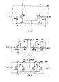
- FIGS. 5a, 5b, 5c, 5d, 5e and 5f show a more complex preferred embodiment of the invention which incorporates both active and passive mixers.
- This arrangement is for use in a system employing dual local oscillators for conversion, but the invention in equally suitable for any application requiring one or more mixing stages.
- Figure 5a shows the main elements or stages of the circuit, which are the input RF amplifier (5b) 500, active mixers (5c) and (5d) 540, 550, in the form of switches driven from a first local oscillator LO1_I+, LO1_I-, LO1_Q+, LO1_Q-, and passive mixers (5e) and (5f) 530, 520 driven from a second local oscillator LO2_I+, LO2_I-, LO2_Q+, LO2_Q-.
- Each element or stage 500, 520, 530, 540, 550 shown in Figure 5a is expanded to show more detail in the Figures 5b, 5c, 5d, 5e, and 5f.
- Figure 5a shows the main elements or stages of the circuit, which are the input RF amplifier (5b) 500, active mixers (5c) and (5d) 540, 550, in the form of switches driven from a first local oscillator LO1_I+, LO1_
- Figure 5b illustrating the RF amplifier stage in which the incoming signal is amplified by transistors 501, 502 before being presented to the active mixers 520, 530.
- the current required to permit this stage to operate efficiently is provided largely by the current injection circuit shown in Figure 5a comprised of a constant current source 570, and resistors 584 and 586. Some part of the current is also provided by the active mixer stages (5c) 540, and (5d) 520.
- the magnitude of this current, and the values of the resistors 588 and 590 which bias gates of transistors 501, 502 are selected so that the transistors are working in their linear region with optimised gain and noise performance.
- resistors 584, 586 control the gain of the RF amplifier stages. Resistors 584, 586 may be adjustable in the factory using laser trimming or another suitable technology. In a further embodiment resistors 584, 586 are replaced by transistors and are field adjustable, indirectly by some form of manual control, or automatically by being driven from some derived measurement of the performance of the overall circuit.
- Each of these circuits comprises four transistors acting as switches 503, 504, 505, and 506, and 507, 508, 509, and 510, respectively, arranged so that the incoming amplified RF signals l1 and l2 are selectively coupled to the outputs O1, O2, O3 and O4 according to the local oscillator inputs LO1_Q and LO1_I, thereby multiplying or mixing the LO with the incoming RF signal to produce intermediate frequencies (or in the case of homodyne systems, baseband signals) in quadrature for passing to the next stage of the circuit.
- each of the transistors are connected together for each mixer, and provide that fraction of the source current for the RF amplifier not provided by the current injection circuit 570, 584, 586 described earlier.
- Each of the switches 503, 504, 505, 506, 507, 508, 509, 510 for first local oscillator must be matched for gain and other parameters to ensure suitable performance characteristics.
- the current through the switches 503, 504, 505, 506, 507, 508, 509, 510 must also be selected carefully. If it is too low the conversion gain is reduced but if it is too high the noise figure increases.
- the ratio of current passing through the switches to that passing through the RF transistors must be adjusted for each design to arrive at the required compromise of gain and noise performance. It has been found that a ratio of approximately 1/25 is a good design starting point.
- V d The voltage (V d ) applied to the drain of switches 503, 504, 505, 506, 507, 508, 509, 510 is somewhat critical. If it is too high the passive mixer cannot work properly. The following conditions should both be met: V on -V d > V th and V off -V d ⁇ V th Where V on and V off are the voltage levels applied to the gates of passive mixer switches to turn them on and off respectively.
- the outputs O1, O2, O3 and O4 of the dual active mixers are then passed to a further pair of passive mixers 530, 520 shown in detail in Figures 5e and 5f, to which we now turn.
- Each figure shows near identical passive mixers, in which transistors 511, 512, 513 and 514, and 515, 516, 517 and 518, are connected as diodes in a well-known passive mixer format.
- a second local oscillator frequency LO2_Q and LO2_I is then mixed with the components generated by the active mixers to produce the final output of the mixer stages OUT_Q and OUT_I respectively,
- Capacitors 562, 564, 566, 568 act as low-pass filters to remove local oscillator and carrier frequencies.
- Each of the I and Q passive switches 511, 512, 513, 514, 515, 516, 517, 518 for the second local oscillator must be matched for gain.
- the various pairs of resistors 592 with 565, 594 with 567, 596 with 561, and 598 with 563 act as voltage dividers for fixing the DC biasing of their respective mixer transistors, and thereby affect the linearity of mixer performance.
- the selection of the ratio of each pair of voltage divider resistors values (e.g. 565 and 592) must be accompanied by the consideration of their combined series resistance, since they can have same ratio with different values. If the combined series resistance is set too high in order to achieve a higher overall conversion gain then the noise figure of mixers is increased, and vice versa.
- Each design decision depends on the overall system requirements, and the values must be selected accordingly,
- the values of the gain-controlling resistors 584, 586 can be adjusted to vary the overall conversion gain of the mixer performance during the final stages of manufacture, In another preferred embodiment, the gain-controlling resistors are replaced by gain-controlling transistors. Monitoring of signal strength allows the system to provide Automatic Gain Control (AGC), as reception conditions vary by applying an appropriate signal to the gates of the gain-controlling transistors.
- AGC Automatic Gain Control
- the manufacturer during the manufacturing process, or the wireless terminal itself during operation is able to vary a number of interacting parameters and select the most applicable compromise available to it.
Landscapes
- Engineering & Computer Science (AREA)
- Power Engineering (AREA)
- Amplifiers (AREA)
- Superheterodyne Receivers (AREA)
- Circuits Of Receivers In General (AREA)
Applications Claiming Priority (3)
| Application Number | Priority Date | Filing Date | Title |
|---|---|---|---|
| CA2375438 | 2002-03-08 | ||
| US10/094,324 US6639447B2 (en) | 2002-03-08 | 2002-03-08 | High linearity Gilbert I Q dual mixer |
| CA002375438A CA2375438A1 (en) | 2002-03-08 | 2002-03-08 | Improvements to a high linearity gilbert i q dual mixer |
Publications (2)
| Publication Number | Publication Date |
|---|---|
| EP1363392A2 true EP1363392A2 (de) | 2003-11-19 |
| EP1363392A3 EP1363392A3 (de) | 2004-05-26 |
Family
ID=29585107
Family Applications (1)
| Application Number | Title | Priority Date | Filing Date |
|---|---|---|---|
| EP03004967A Withdrawn EP1363392A3 (de) | 2002-03-08 | 2003-03-10 | Gilbert-Zelle-Mischer |
Country Status (3)
| Country | Link |
|---|---|
| US (1) | US6639447B2 (de) |
| EP (1) | EP1363392A3 (de) |
| CA (1) | CA2375438A1 (de) |
Cited By (5)
| Publication number | Priority date | Publication date | Assignee | Title |
|---|---|---|---|---|
| WO2007073259A1 (en) * | 2005-12-22 | 2007-06-28 | Infineon Technologies Ag | Mixer circuit and rf transmitter using such mixer circuit |
| WO2008079067A1 (en) * | 2006-12-22 | 2008-07-03 | Telefonaktiebolaget Lm Ericsson | Method and arrangement for a linear mixer |
| CN102545786A (zh) * | 2010-12-09 | 2012-07-04 | 上海华虹集成电路有限责任公司 | 射频识别中的高线性度混频器 |
| RU2458456C1 (ru) * | 2011-04-20 | 2012-08-10 | Государственное образовательное учреждение высшего профессионального образования "Южно-Российский государственный университет экономики и сервиса" (ГОУ ВПО "ЮРГУЭС") | Аналоговый смеситель двух сигналов |
| CN103748785A (zh) * | 2011-08-03 | 2014-04-23 | 爱立信调制解调器有限公司 | 高效功率放大器 |
Families Citing this family (58)
| Publication number | Priority date | Publication date | Assignee | Title |
|---|---|---|---|---|
| US6871057B2 (en) * | 2000-03-08 | 2005-03-22 | Nippon Telegraph And Telephone Corporation | Mixer circuit |
| AU2002240055A1 (en) * | 2001-01-25 | 2002-08-06 | Regents Of The University Of Minnesota | High linearity circuits and methods regarding same |
| US6889038B2 (en) * | 2001-04-06 | 2005-05-03 | Koninklijke Philips Electronics N.V. | Dynamic biasing of a transmitter |
| US6865382B2 (en) * | 2002-01-07 | 2005-03-08 | Broadcom Corp. | Mixer having low noise, controllable gain, and/or low supply voltage operation |
| US6850753B2 (en) * | 2002-06-11 | 2005-02-01 | Muchip Co., Ltd | Tunable low noise amplifier and current-reused mixer for a low power RF application |
| US8816750B2 (en) | 2002-07-17 | 2014-08-26 | Broadcom Corporation | High frequency mixer with tunable dynamic range |
| US6889037B2 (en) * | 2002-08-20 | 2005-05-03 | Broadcom Corporation | Reducing active mixer flicker noise |
| KR100790858B1 (ko) * | 2002-09-04 | 2008-01-02 | 삼성전자주식회사 | 시공유 i 채널 및 q 채널을 가진 직접변환 수신기 및수신방법 |
| US7006824B1 (en) | 2002-09-10 | 2006-02-28 | Marvell International Ltd. | Frame/packet-based calibration for wireless transceivers |
| US7215933B1 (en) | 2002-09-24 | 2007-05-08 | Marvell International Ltd. | Local transmitter output power control system for wireless applications |
| US6983135B1 (en) | 2002-11-11 | 2006-01-03 | Marvell International, Ltd. | Mixer gain calibration method and apparatus |
| US7248850B2 (en) * | 2002-12-10 | 2007-07-24 | Nanoamp Solutions, Inc. | Passive subharmonic mixer design |
| JP2006511153A (ja) * | 2002-12-19 | 2006-03-30 | コーニンクレッカ フィリップス エレクトロニクス エヌ ヴィ | ZIFミキサ用1/f雑音波形最小化 |
| EP1450480A1 (de) * | 2003-02-18 | 2004-08-25 | STMicroelectronics S.r.l. | Rauscharmer Multiplizierer mit hoher Linearität |
| US7010330B1 (en) | 2003-03-01 | 2006-03-07 | Theta Microelectronics, Inc. | Power dissipation reduction in wireless transceivers |
| US7299025B1 (en) * | 2003-06-09 | 2007-11-20 | National Semiconductor Corporation | Harmonic rejection gated-switching mixer |
| US7565128B2 (en) * | 2003-09-23 | 2009-07-21 | Nxp B.V. | High performance low noise amplifier |
| ATE391359T1 (de) * | 2003-12-10 | 2008-04-15 | Ericsson Telefon Ab L M | Mischervorrichtung |
| KR101051568B1 (ko) * | 2003-12-10 | 2011-07-22 | 텔레폰악티에볼라겟엘엠에릭슨(펍) | 혼합 장치 |
| TWI345369B (en) * | 2004-01-28 | 2011-07-11 | Mediatek Inc | High dynamic range time-varying integrated receiver for elimination of off-chip filters |
| US7161406B1 (en) * | 2004-04-15 | 2007-01-09 | Xilinx, Inc. | Method and apparatus for providing non 2:1 Gilbert cell mixer |
| US7046068B2 (en) * | 2004-04-27 | 2006-05-16 | Broadcom Corporation | CMOS-based receiver for communications applications |
| US7236763B2 (en) * | 2004-06-04 | 2007-06-26 | Motorola, Inc. | Method and apparatus providing improved mixer performance for radio receivers |
| KR100574470B1 (ko) * | 2004-06-21 | 2006-04-27 | 삼성전자주식회사 | 전류증폭결합기를 포함하는 선형 혼합기회로 |
| DE102005005332A1 (de) * | 2005-01-28 | 2006-08-10 | Atmel Germany Gmbh | Mischstufe und Verfahren zur Mischung von Signalen verschiedener Frequenzen |
| KR100643768B1 (ko) | 2005-07-01 | 2006-11-10 | 삼성전자주식회사 | 믹서 |
| US8145155B2 (en) * | 2005-09-06 | 2012-03-27 | Mediatek, Inc. | Passive mixer and high Q RF filter using a passive mixer |
| US7398073B2 (en) * | 2005-09-06 | 2008-07-08 | Skyworks Solutions, Inc. | Low noise mixer |
| US7912429B2 (en) * | 2005-09-06 | 2011-03-22 | Mediatek, Inc. | LO 2LO upconverter for an in-phase/quadrature-phase (I/Q) modulator |
| US20070060087A1 (en) * | 2005-09-10 | 2007-03-15 | Zhaofeng Zhang | Low noise high linearity downconverting mixer |
| US7512393B2 (en) * | 2005-10-14 | 2009-03-31 | Skyworks Solutions, Inc. | Downconverting mixer |
| US7355466B2 (en) * | 2006-01-26 | 2008-04-08 | Honeywell International Inc. | Passive mixer with direct current bias |
| US7755415B2 (en) * | 2006-04-24 | 2010-07-13 | Analog Devices, Inc. | Transistor cell and related circuits and methods |
| US20080009260A1 (en) * | 2006-07-10 | 2008-01-10 | Mediatek Inc. | Mixer with dynamic intermediate frequency for radio-frequency front-end and method using the same |
| US7769361B2 (en) * | 2006-07-19 | 2010-08-03 | Qualcomm Incorporated | Systems, methods, and apparatus for frequency conversion |
| US7962114B2 (en) * | 2007-01-12 | 2011-06-14 | International Business Machines Corporation | Drain-pumped sub-harmonic mixer for millimeter wave applications |
| GB2446463A (en) * | 2007-02-09 | 2008-08-13 | Acp Advanced Circuit Pursuit A | Mixer with shorting switch |
| US7725092B2 (en) * | 2007-04-06 | 2010-05-25 | Mediatek Inc. | Dynamic current steering mixer |
| US20080284489A1 (en) * | 2007-05-14 | 2008-11-20 | Mediatek Singapore Pte Ltd | Transconductor and mixer with high linearity |
| US8045944B2 (en) | 2007-09-14 | 2011-10-25 | Qualcomm Incorporated | Offset correction for passive mixers |
| KR101472799B1 (ko) * | 2008-06-11 | 2014-12-16 | 삼성전자주식회사 | 유기발광 디스플레이 장치 및 구동방법 |
| US20100056095A1 (en) * | 2008-09-02 | 2010-03-04 | Mediatek Inc. | Dynamic current injection mixer/modulator |
| US7889008B2 (en) * | 2009-06-08 | 2011-02-15 | Mediatek Inc. | Programmable gain MOS amplifier |
| US8179198B2 (en) * | 2009-07-31 | 2012-05-15 | Texas Instruments Incorporated | Variable gain amplifier having automatic power consumption optimization |
| KR101079373B1 (ko) | 2009-08-12 | 2011-11-02 | 삼성전기주식회사 | 차동 직류 옵셋 제거기능을 갖는 믹서 |
| ES2566754T3 (es) | 2009-10-23 | 2016-04-15 | Telefonaktiebolaget Lm Ericsson (Publ) | Mezclador pasivo con intermodulación de segundo orden reducida |
| US8593206B2 (en) * | 2011-04-12 | 2013-11-26 | Taiwan Semiconductor Manufacturing Company, Ltd. | Up-conversion mixer having a reduced third order harmonic |
| CN103999358B (zh) | 2011-12-15 | 2017-09-01 | 马维尔国际贸易有限公司 | 具有对过程、温度和负载阻抗变化的不灵敏的rf功率检测电路 |
| US8493127B1 (en) * | 2012-03-13 | 2013-07-23 | Fujitsu Semiconductor Limited | System and method for linearization of a mixer |
| US8754700B1 (en) * | 2012-12-31 | 2014-06-17 | Futurewei Technologies, Inc. | Linearity improvement over temperature using temperature dependent common-mode voltages in active mixer |
| TWI524660B (zh) | 2013-12-27 | 2016-03-01 | 瑞昱半導體股份有限公司 | 主動式混頻器與主動式混頻方法 |
| US9748993B2 (en) * | 2015-09-08 | 2017-08-29 | Mediatek Inc. | Radio frequency receiver front-end with gain control capability as well as improved impedance matching control capability |
| EP3909126A4 (de) * | 2019-01-11 | 2022-11-23 | Academia Sinica | Mischschaltkreis |
| US10778148B1 (en) | 2019-12-13 | 2020-09-15 | Raytheon Company | Gain and sensitivity in a Gilbert switch stage |
| CN112054770A (zh) * | 2020-09-04 | 2020-12-08 | 中筑科技股份有限公司 | 一种应用于远程控制系统的混频器电路及射频标签电路 |
| US11277108B1 (en) * | 2020-12-28 | 2022-03-15 | Analog Devices International Unlimited Company | Variable gain amplifiers with cross-couple switching arrangements |
| CN113157034B (zh) * | 2021-01-19 | 2022-06-03 | 浙江大学 | 一种被动稳压电路实现的高线性度神经形态计算电路 |
| CN115051564B (zh) * | 2022-06-27 | 2025-09-16 | 上海集成电路研发中心有限公司 | 芯片内部供电电路及其控制方法 |
Family Cites Families (11)
| Publication number | Priority date | Publication date | Assignee | Title |
|---|---|---|---|---|
| US3805162A (en) * | 1970-05-28 | 1974-04-16 | Motorola Inc | Miniature, low voltage, low current receiver front end |
| US5625307A (en) * | 1992-03-03 | 1997-04-29 | Anadigics, Inc. | Low cost monolithic gallium arsenide upconverter chip |
| ES2153849T3 (es) * | 1994-11-07 | 2001-03-16 | Cit Alcatel | Mezclador de transmision con entrada en modo de corriente. |
| US6040731A (en) * | 1997-05-01 | 2000-03-21 | Raytheon Company | Differential pair gain control stage |
| US5920810A (en) * | 1997-05-05 | 1999-07-06 | Motorola, Inc. | Multiplier and method for mixing signals |
| US5859559A (en) * | 1997-07-31 | 1999-01-12 | Raytheon Company | Mixer structures with enhanced conversion gain and reduced spurious signals |
| US6073002A (en) * | 1998-05-04 | 2000-06-06 | Motorola | Mixer circuit and communication device using the same |
| US6438365B1 (en) * | 1998-06-02 | 2002-08-20 | Philsar Semiconductor Inc. | Balanced mixer with feedback pre-amplifier |
| US6313688B1 (en) * | 1998-07-24 | 2001-11-06 | Gct Semiconductor, Inc. | Mixer structure and method of using same |
| US6393266B1 (en) * | 1999-03-02 | 2002-05-21 | Conexant Systems, Inc. | Preprocessor and related frequency translator |
| JP2001344559A (ja) * | 2000-05-30 | 2001-12-14 | Matsushita Electric Ind Co Ltd | アナログ乗算回路および可変利得増幅回路 |
-
2002
- 2002-03-08 CA CA002375438A patent/CA2375438A1/en not_active Abandoned
- 2002-03-08 US US10/094,324 patent/US6639447B2/en not_active Expired - Lifetime
-
2003
- 2003-03-10 EP EP03004967A patent/EP1363392A3/de not_active Withdrawn
Cited By (7)
| Publication number | Priority date | Publication date | Assignee | Title |
|---|---|---|---|---|
| WO2007073259A1 (en) * | 2005-12-22 | 2007-06-28 | Infineon Technologies Ag | Mixer circuit and rf transmitter using such mixer circuit |
| US8260218B2 (en) | 2005-12-22 | 2012-09-04 | Intel Mobile Communications GmbH | Mixer circuit and RF transmitter using such mixer circuit |
| WO2008079067A1 (en) * | 2006-12-22 | 2008-07-03 | Telefonaktiebolaget Lm Ericsson | Method and arrangement for a linear mixer |
| CN102545786A (zh) * | 2010-12-09 | 2012-07-04 | 上海华虹集成电路有限责任公司 | 射频识别中的高线性度混频器 |
| RU2458456C1 (ru) * | 2011-04-20 | 2012-08-10 | Государственное образовательное учреждение высшего профессионального образования "Южно-Российский государственный университет экономики и сервиса" (ГОУ ВПО "ЮРГУЭС") | Аналоговый смеситель двух сигналов |
| CN103748785A (zh) * | 2011-08-03 | 2014-04-23 | 爱立信调制解调器有限公司 | 高效功率放大器 |
| CN103748785B (zh) * | 2011-08-03 | 2017-07-18 | 瑞典爱立信有限公司 | 高效功率放大器 |
Also Published As
| Publication number | Publication date |
|---|---|
| EP1363392A3 (de) | 2004-05-26 |
| US6639447B2 (en) | 2003-10-28 |
| CA2375438A1 (en) | 2003-09-08 |
| US20030169089A1 (en) | 2003-09-11 |
Similar Documents
| Publication | Publication Date | Title |
|---|---|---|
| US6639447B2 (en) | High linearity Gilbert I Q dual mixer | |
| US7474885B2 (en) | Passive subharmonic mixer | |
| US7062248B2 (en) | Direct conversion receiver having a low pass pole implemented with an active low pass filter | |
| TWI360941B (en) | Adaptive-biased mixer | |
| US7016664B2 (en) | Mixer circuit arrangement and an image-reject mixer circuit arrangement | |
| US8018267B2 (en) | Frequency conversion mixer | |
| US7277682B2 (en) | RF passive mixer with DC offset tracking and local oscillator DC bias level-shifting network for reducing even-order distortion | |
| US20050088204A1 (en) | High linearity passive mixer and associated LO buffer | |
| EP3176946B1 (de) | Rauscharme transkonduktanzverstärker | |
| US6590438B1 (en) | Integrated circuit adjustable RF mixer | |
| EP1704649B1 (de) | Vielseitiger Splitter für Basisband-Stromeingangs-Signal | |
| US6973290B2 (en) | Radio architecture | |
| US6591093B1 (en) | Circuit and method for frequency translation | |
| US7215940B2 (en) | Integrated circuit | |
| Liu et al. | A 2.4 GHz receiver with a current-reused inductor-less noise-canceling balun LNA in 40 nm CMOS | |
| US20060170496A1 (en) | Signal processing circuit and communication device using the same | |
| US7126424B2 (en) | Interface circuit for connecting to an output of a frequency converter | |
| US20060091944A1 (en) | I/Q quadrature demodulator | |
| US7088982B1 (en) | Gilbert cell and method thereof | |
| US6965653B2 (en) | Circuit and method for processing an automatic frequency control signal | |
| US8260218B2 (en) | Mixer circuit and RF transmitter using such mixer circuit | |
| Perumana et al. | A subharmonic CMOS mixer based on threshold voltage modulation | |
| EP1343248B1 (de) | Gilbert-Zellen-Mischer | |
| Gao et al. | Study of flicker noise for zero-IF receiver | |
| Gao et al. | A high-linearity low-noise figure active mixer in 0.18 um CMOS |
Legal Events
| Date | Code | Title | Description |
|---|---|---|---|
| PUAI | Public reference made under article 153(3) epc to a published international application that has entered the european phase |
Free format text: ORIGINAL CODE: 0009012 |
|
| AK | Designated contracting states |
Kind code of ref document: A2 Designated state(s): AT BE BG CH CY CZ DE DK EE ES FI FR GB GR HU IE IT LI LU MC NL PT SE SI SK TR |
|
| AX | Request for extension of the european patent |
Extension state: AL LT LV MK RO |
|
| PUAL | Search report despatched |
Free format text: ORIGINAL CODE: 0009013 |
|
| AK | Designated contracting states |
Kind code of ref document: A3 Designated state(s): AT BE BG CH CY CZ DE DK EE ES FI FR GB GR HU IE IT LI LU MC NL PT SE SI SK TR |
|
| AX | Request for extension of the european patent |
Extension state: AL LT LV MK RO |
|
| 17P | Request for examination filed |
Effective date: 20041126 |
|
| AKX | Designation fees paid |
Designated state(s): AT BE BG CH CY CZ DE DK EE ES FI FR GB GR HU IE IT LI LU MC NL PT SE SI SK TR |
|
| 17Q | First examination report despatched |
Effective date: 20070312 |
|
| STAA | Information on the status of an ep patent application or granted ep patent |
Free format text: STATUS: THE APPLICATION IS DEEMED TO BE WITHDRAWN |
|
| 18D | Application deemed to be withdrawn |
Effective date: 20070724 |