EP1363481A2 - Leiterplatte mit einem Wärmerohr - Google Patents
Leiterplatte mit einem Wärmerohr Download PDFInfo
- Publication number
- EP1363481A2 EP1363481A2 EP03300012A EP03300012A EP1363481A2 EP 1363481 A2 EP1363481 A2 EP 1363481A2 EP 03300012 A EP03300012 A EP 03300012A EP 03300012 A EP03300012 A EP 03300012A EP 1363481 A2 EP1363481 A2 EP 1363481A2
- Authority
- EP
- European Patent Office
- Prior art keywords
- heat pipe
- heat
- circuit board
- electronic components
- insulating layer
- Prior art date
- Legal status (The legal status is an assumption and is not a legal conclusion. Google has not performed a legal analysis and makes no representation as to the accuracy of the status listed.)
- Granted
Links
Images




Classifications
-
- H—ELECTRICITY
- H05—ELECTRIC TECHNIQUES NOT OTHERWISE PROVIDED FOR
- H05K—PRINTED CIRCUITS; CASINGS OR CONSTRUCTIONAL DETAILS OF ELECTRIC APPARATUS; MANUFACTURE OF ASSEMBLAGES OF ELECTRICAL COMPONENTS
- H05K7/00—Constructional details common to different types of electric apparatus
- H05K7/20—Modifications to facilitate cooling, ventilating, or heating
- H05K7/2029—Modifications to facilitate cooling, ventilating, or heating using a liquid coolant with phase change in electronic enclosures
- H05K7/20336—Heat pipes, e.g. wicks or capillary pumps
-
- F—MECHANICAL ENGINEERING; LIGHTING; HEATING; WEAPONS; BLASTING
- F28—HEAT EXCHANGE IN GENERAL
- F28D—HEAT-EXCHANGE APPARATUS, NOT PROVIDED FOR IN ANOTHER SUBCLASS, IN WHICH THE HEAT-EXCHANGE MEDIA DO NOT COME INTO DIRECT CONTACT
- F28D15/00—Heat-exchange apparatus with the intermediate heat-transfer medium in closed tubes passing into or through the conduit walls ; Heat-exchange apparatus employing intermediate heat-transfer medium or bodies
- F28D15/02—Heat-exchange apparatus with the intermediate heat-transfer medium in closed tubes passing into or through the conduit walls ; Heat-exchange apparatus employing intermediate heat-transfer medium or bodies in which the medium condenses and evaporates, e.g. heat pipes
- F28D15/0233—Heat-exchange apparatus with the intermediate heat-transfer medium in closed tubes passing into or through the conduit walls ; Heat-exchange apparatus employing intermediate heat-transfer medium or bodies in which the medium condenses and evaporates, e.g. heat pipes the conduits having a particular shape, e.g. non-circular cross-section, annular
-
- H—ELECTRICITY
- H05—ELECTRIC TECHNIQUES NOT OTHERWISE PROVIDED FOR
- H05K—PRINTED CIRCUITS; CASINGS OR CONSTRUCTIONAL DETAILS OF ELECTRIC APPARATUS; MANUFACTURE OF ASSEMBLAGES OF ELECTRICAL COMPONENTS
- H05K1/00—Printed circuits
- H05K1/02—Details
- H05K1/0272—Adaptations for fluid transport, e.g. channels, holes
-
- F—MECHANICAL ENGINEERING; LIGHTING; HEATING; WEAPONS; BLASTING
- F28—HEAT EXCHANGE IN GENERAL
- F28F—DETAILS OF HEAT-EXCHANGE AND HEAT-TRANSFER APPARATUS, OF GENERAL APPLICATION
- F28F2275/00—Fastening; Joining
- F28F2275/20—Fastening; Joining with threaded elements
Definitions
- the present invention relates to a heat pipe circuit board having its own cooling function for improving the performance of dissipating heat generated by electronic components.
- An electronic component is usually mounted on a printed board to constitute a predetermined electronic circuit with other electronic components.
- the printed board is a thin plate made of an insulating material. On the surface of the printed board, there is printed a metal material with high electrical conductivity, such as copper or the like, so as to constitute a predetermined circuit.
- the printed board has a hole at a position where an electronic component is mounted, and the electronic component is jointed onto the printed board by soldering or another jointing method to make up a predetermined electronic circuit.
- the printed board itself has low heat conductivity and does not have any particular cooling function.
- heat-dissipating means there is a method for connecting a heat sink which is made of metal having high heat conductivity. Further, this method is often used in combination with cooling by a cooling fan.
- a heat pipe is provided in direct contact with the electronic component.
- a heat pipe is often provided in contact with a printed board on which the electronic component is mounted.
- the heat pipe is typically made of metal having relatively high heat conductivity such as copper or aluminum. Between the printed board and the heat pipe, an insulating material having extremely high heat conductivity is inserted to achieve excellent heat conductivity while keeping electrical insulation.
- the printed board and the heat pipe are jointed by a mechanical joint method, a method of using an adhesive agent or the like.
- the adhesive agent also performs the function of the above-mentioned insulating material having high heat conductivity.
- Heat generated by electronic components passes through the printed board and the insulating material inserted between the printed board and the heat pipe, then to be transferred to an outer wall of a heat receiving portion of the connected heat pipe.
- the heat is further transferred from the outer wall of the heat receiving portion of the heat pipe to an inner wall thereof then to be conducted to a working fluid stored in the heat receiving portion in a fluid channel of the heat pipe.
- the working fluid is vaporized by the conducted heat, and then, the vaporized working fluid is moved to reach a heat dissipating portion of the heat pipe.
- An outer wall of the heat dissipating portion is provided with heat dissipating fins or the like so as to dissipate heat to the outside.
- the vaporized working fluid is deprived of heat by being brought into contact with an inner wall of the heat dissipating portion of the heat pipe, and the heat deprived of from the working fluid is transferred from the inner wall of the heat pipe to the outer wall to be dissipated into the air by external cooling fins or the like.
- a cooling fan is sometimes arranged.
- the working fluid deprived of heat at the heat dissipating portion is changed from gas back to liquid.
- the liquefied working fluid flows in the fluid channel back to the heat receiving portion by gravity or capillary force. Then, the above-described cycle is repeated.
- a heat pipe utilizes evaporation heat of a working fluid, it is a method which enables efficient heat transfer.
- heat generated by electronic components is transferred to a heat pipe via a printed board. Since the heat conductivity of the printed board per se is not as high as that of metal and the like, much thermal resistance exists between the electronic components and the heat pipe. Therefore, even if a high-performance heat pipe is installed, this thermal resistance may prevent heat generated by the electronic component from being dissipated efficiently.
- Jointing methods of metal plates include welding, brazing, pressure-bonding and the like.
- welding since raw materials are fused to be jointed, a large amount of heat is given to the metal plates, which results in creating distortion due to the heat in the metal plates. Besides, there occur bumps in a welded portion of the metal plates, which can not be smooth.
- the welding method since in the welding method, there occurs sputtering gas or welding gas and much energy is applied, additional cost, time and effort may be necessitated to create an appropriate clean environment that handles electronic components. Furthermore, the welding method needs additional materials including a welding rod, shielding gas and the like.
- the brazing method is a high-temperature process at a temperature of 600 degree or higher, which is not higher than the temperature of welding method, but is high enough to produce distortion in the metal plates. Besides, there occur bumps in a brazed portion of the metal plates, which can not be smooth. Therefore, there arise substantially the same problems as those in the welding method.
- a heat pipe manufactured by pressure-bonding does not have such problems as distortion, bumps, high heat in welding and an environmental problem that are shown in the welding and brazing method.
- the joint strength in pressure-bonding is lower than that of the other methods, and therefore, the pressure-bonding method is not suitable for use in a situation of exposure to thumps, bumps and vibration.
- the inventors of the present invention have intensively studied in order to solve the above-mentioned problems. As a result, they have found that a heat pipe circuit board described below is capable of transferring heat generated by electronic components to a cooling device more efficiently than the conventional art to enhance cooling performance. In addition, by adopting fiction stir welding which does not generate high heat in jointing, they have achieved a heat pipe circuit board manufacturing method of jointing the heat pipe plates after electronic components are mounted thereon.
- a first embodiment of the heat pipe circuit board according to the present invention is a heat pipe circuit board comprising: a heat pipe; at least one insulating layer; a circuit pattern provided on a surface of or inside said at least one insulating layer; and electronic components being mounted on said heat pipe on said insulating layer.
- a second embodiment of the heat pipe circuit board according to the present invention is a heat pipe circuit board in which said heat pipe is formed by jointing two plate members by friction stir welding, at least one of said two plate members being provided with a recess portion which is a fluid channel of a working fluid.
- a third embodiment of the heat pipe circuit board according to the present invention is a heat pipe circuit board in which said at least one insulating layer takes the shape of a sheet or a plate.
- a fourth embodiment of the heat pipe circuit board according to the present invention is a heat pipe circuit board in which said at least one insulating layer is formed by a coating.
- a fifth embodiment of the heat pipe circuit board according to the present invention is a heat pipe circuit board in which said at least one insulating layer is strong enough to support said electronic components by itself.
- a sixth embodiment of the heat pipe circuit board according to the present invention is a heat pipe circuit board in which said heat pipe includes a cooling surface, said cooling surface performing the function of a mounting bracket for mounting said peat pipe on another member.
- a first embodiment of the heat pipe circuit board manufacturing method according to the present invention is a heat pipe circuit board manufacturing method wherein two plate members are prepared, at least one of the plate members being provided with a recess portion which is a fluid channel of a working fluid, electronic components being mounted on at least one of the plate members via an insulating layer, and then, the plate members being jointed by friction stir welding.
- Another embodiment of the heat pipe circuit board according to the present invention is a heat pipe circuit board in which said electronic components are mounted on said two plate members via said at least one insulating member.
- Still another embodiment of the heat pipe circuit board according to the present invention is a heat pipe circuit board in which said electronic components are mounted on either of said two plate members via said at least one insulating member.
- Fig. 1 shows an embodiment of a heat pipe 1 on which relatively miniaturized electronic components 3 are mounted via an insulating layer 2 having a circuit pattern;
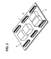
- Fig. 2 shows an embodiment of a heat pipe 4 on which relatively large electronic components 6 and relatively miniaturized electronic components 7 are mounted via an insulating layer 5 having a circuit pattern.
- Figs. 3 and 4 shows cross sections of configurations of heat pipe circuit boards. Both of the embodiments shows a heat pipe formed by jointing two metal plates by friction stir welding, at least one of the metal plates being provided with a fluid channel.
- electronic components are mounted on one of the two plate members of the heat pipe.
- the electronic components 11 are mounted on the heat pipe 17 via insulating layers 12 and 13.
- the heat pipe 17 is formed by a plate member 14 and a plate member 15 jointed to be one piece.
- the plate members 14 and 15 are typically made of metal having high heat conductivity, such as copper, aluminum or the like, however the plate members may be made of resin such as plastic or the like.
- the plate member 14 has a recess portion formed to be a fluid channel of a working fluid.
- the recess portion is formed by machine working, bending, forging or the like. In the present embodiment, the recess portion is formed only in the plate member 14, however, the recess portion may be formed in each of the plate members 14 and 15.
- the plate members 14 and 15 are jointed by friction stir welding.
- the method for jointing plate members by friction stir welding will be described in detail later.
- At least one of the plate members 14 and 15 is provided with an inlet for injecting a working fluid into the fluid channel of the working fluid. A predetermined amount of the working fluid is injected from the inlet and the inlet is sealed by the above-mentioned friction stir welding so that the fluid channel is hermetically sealed to be in a vacuum state.
- a circuit pattern is provided based on each circuit design for electrically connecting given electronic components to constitute an electronic circuit.
- This circuit pattern is made of a conductive material having high electrical conductivity such as copper.
- the insulating layer 12 may be in the form of a sheet, a plate or be formed by coating of an insulating material. Particularly, when this circuit board is mounted in an auto mobile, the insulating layer 12 per se is required to be strong enough to support electronic components against severe heat conditions, heavy impact load and frequent occurrence of vibrations in the auto mobile.
- Electronic components 11 are jointed to the above-mentioned circuit pattern by soldering, mechanical-joint or the like so as to establish electrical connection.
- the insulating layer 13 has the function of insulating conductive portions of the circuit pattern or the electronic components from the plate member 14 when the conductive portions are exposed at the plate-member-14-side surface of the insulating layer 12. When the conductive portions are not exposed, the insulating layer 13 has the function of an adhesive agent for adhering the insulating layer 12 and the plate member 14 to one another and the function of enhancing heat conductivity by increasing adhesion degree.
- Heat generated by the electronic components 11 is transferred to the plate member 14 via the insulating layers 12 and 13.
- thermal resistance is smaller in the present invention and it is possible to cool generated heat efficiently.
- Heat is transferred by thermal conduction inside the plate member 14 then to a working fluid 16 stored in the fluid channel.
- the working fluid 16 is vaporized by the heat and moved to be brought into contact with an inner surface of the plate member 15.
- An outer surface of the plate member 15 is a cooling plate 18.
- the cooling plate 18 may be provided with heat dissipating fins, may be connected to a heat sink or may be in contact with another heat-dissipating member. Accordingly, the inner surface of the plate member 15 has a temperature lower than that of the vaporized working fluid 16, and then, the vaporized working fluid 16 is deprived of heat when the working fluid 16 is in contact with the inner surface of the plate member 15. The heat deprived of from the working fluid 16 is transferred via the plate member 15 to the outer surface thereof by heat conductivity and dissipated from the surface of the cooling plate 18.
- the vaporized working fluid 16 is deprived of heat by the plate member 15 to become liquefied again.
- the liquefied working fluid is conducted by gravity or capillary force through the fluid channel of the working fluid into the original position where the working fluid was stored. Then, the working fluid is heated by heat conducted from the inner surface of the plating member 14 to be vaporized again, thereby repeating such heating cycle.
- Fig. 4 shows an embodiment in which electronic components are mounted on both of two plate members which comprise a cooling device equipped board.
- These plate members have not only portions for mounting electronic components thereon but also portions which, next to the electronic components-mounted portions, function as cooling surfaces.
- the cooling surface portions also function as mounting brackets for mounting the cooling device equipped board per se on another member.
- the heat pipe 26 is formed by plate members 24 and 25 jointed to be one piece.
- each of the plate members 24 and 25 is an L-shaped member and consists of an electronic-components-mounted portion and a cooling surface portion.
- the cooling surface portion is provided on each of the plate members 24 and 25 has in the present embodiment, however, it may be provided on either of the plate members.
- the plate member 24 and the plate member 25 are made of metal having high heat conductivity, such as copper, aluminum or the like, however the plate members may be made of resin such as plastic or the like.
- the plate member 24 has a recess portion formed to be a fluid channel of a working fluid.
- the fluid channel of a working fluid is formed not only at the electronic-components-mounted portion but also at the cooling surface portion.
- the recess portion is formed by machine working, bending, forging or the like. In the present embodiment, the recess portion is formed only in the plate member 24, however, a recess portion may be formed in each of the plate members 24 and 25.
- the plate members 24 and 25 are jointed by friction stir welding.
- the method for jointing plate members by friction stir welding will be described in detail later.
- At least one of the plate members 24 and 25 is provided with an inlet for injecting a working fluid into the fluid channel of the working fluid. After a predetermined amount of working fluid is injected from the inlet, the inlet is sealed by the above-mentioned friction stir welding so that the fluid channel is hermetically sealed so as to be in a vacuum state.
- a circuit pattern is provided based on each circuit design, for electrically connecting given electronic components to constitute an electronic circuit.
- This circuit pattern is made of a conductive material having high electrical conductivity such as copper.
- the insulating layer 22 may be in the form of a sheet, a plate or be formed by coating of an insulating material. Particularly, when this circuit board is mounted in an auto mobile, the insulating layer 22 per se is required to be strong enough to support electronic components against severe heat conditions, heavy impact load and frequent occurrence of vibrations.
- Electronic components 21 are jointed to the above-mentioned circuit pattern by soldering, mechanical joint or the like so as to establish electrical connection.
- the insulating layer 23 has the function of insulating conductive portions of the circuit pattern or the electronic components from the plate member 24 when the conductive portions are exposed at the plate-member-24-side surface of the insulating layer 22. When the conductive portions are not exposed, the insulating layer 23 has the function of an adhesive agent for adhering the insulating layer 22 and the plate member 24 to each other and the function of enhancing heat conductivity by increasing adhesion degree.
- the plate member 25, just like the plate member 24, has electronic components 27 mounted thereon via insulating layers 28 and 29.
- a mounting method is the same as that of the plate member 24.
- the insulating layer 28 is provided with a circuit pattern like the insulating layer 22.
- the insulating layer 29 has the same function as the insulating layer 23.
- Heat generated by the electronic components 21 and 27 is transferred to the plate members 24 and 25 via the insulating layers 22, 23 and 28, 29, respectively.
- thermal resistance is smaller in the present invention and it is possible to cool generated heat efficiently.
- Heat is transferred by thermal conduction inside the plate members 24 and 25 then to a working fluid 30 stored in the fluid channel.
- the working fluid 30 is vaporized by the heat and moved up in the fluid channel to the cooling surface portion 31 then to be brought into contact with an inner surface of the cooling surface portion 31.
- An outer surface of the cooling surface portion 31 is designed to be cooled by dissipating the heat into the air and by dissipating the heat to a body side member 32 connected to the cooling surface portion 31.
- the cooling surface portion 31 may be provided with finer heat dissipating fins.
- the inner surface of the cooling surface portion 31 has a temperature lower than that of the vaporized working fluid 30, and then, the vaporized working fluid 30 is deprived of heat when the working fluid 30 is in contact with the inner surface of the cooling surface portion 31.
- the heat deprived of from the working fluid is transferred via the cooling surface portion 31 to the outer surface thereof to be dissipated.
- the liquefied working fluid is conducted by gravity or capillary force through the fluid channel of the working fluid into the original position where the working fluid was stored. Then, the working fluid is heated by heat transferred from the inner surfaces of the plating members 24 and 25 to be vaporized again, thereby repeating such heating cycle.
- the cooling surface portion 31 also functions as a mounting bracket for mounting the heat pipe 26 on the main body and is connected to the body-side member 32 by an insulated bolt nut 33.
- Jointed materials may be not only metal but also resin such as plastic and the like.
- the following description is made taking an example of metal.
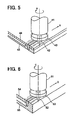
- Fig. 5 shows an embodiment of superposing and jointing two metal plates after one of the metal plates has a recess portion, used as a fluid channel of a working fluid, formed by machine working.
- Fig. 6 shows an embodiment of butt jointing two metal plates after one of the metal plates has a recess portion, used as a fluid channel of a working fluid, formed by machine working, bending or the like.
- FIG. 5 is used to describe a basic jointing method by friction stir welding.
- a jointing apparatus for performing friction stir welding includes: an operating device for moving a tool 41 having a probe 42 and a shoulder 43 in the direction of a weld line (direction of the arrow B in Fig. 5) while rotating the tool 41 (in the direction of the arrow A in Fig. 5); and a clamp device (not shown) for clamping two metal plates 44 and 45 together in such a manner that the metal plates are not moved or detached from each other when the probe 42 is inserted into a position where the metal plates 44 and 45 are superposed.
- the metal plate 45 has a recess portion, which is used as a fluid channel of a working fluid, formed in advance by machine working.
- the two metal plates 44 and 45 are superposed to be jointed.
- the metal plate 55 has a recess portion, which is used as a fluid channel of a working fluid, formed in advance by machine working, bending or the like.
- the two metal plates 44 and 45 are not superposed but butt jointed.
- a jointing apparatus for performing friction stir welding includes: an operating device for moving a tool 51 having a probe 52 and a shoulder 53 in the direction of a weld line (direction of the arrow D in Fig. 6) while rotating the tool 51 (along the direction of the arrow C in Fig. 6); and a clamp device (not shown) for clamping two metal plates 54 and 55 together in such a manner that the metal plates are not moved or detached from each other when the probe 52 is inserted into a position where the metal plates 54 and 55 butt against each other.
- Fig. 7 shows simulation results of a temperature distribution of a heat pipe circuit board according to the present invention.
- Fig. 8 shows simulation results of a temperature distribution of a conventional circuit board provided in contact with a heat pipe.
- the temperature distribution of the heat pipe circuit board according to the present invention is made more uniform than that of the conventional art, and there is found no particular part of higher temperature in the temperature distribution of the present invention. Therefore, although the need to enhance the performance of cooling electronic components is growing as the electronic components are more miniaturized and sophisticated in future, the present invention is adequate to serve such a growing need.
- the present invention is allowed to produce the following effects:
- a heat pipe circuit board according to the present invention is capable of vastly improving cooling performance of heat generated by electronic components. Therefore, according to the present invention, it is possible to be ready for an expected increase of heat which is generated more and more by electronic components due to miniaturization or sophistication of the electronic components in future.
- a conventional heat pipe for cooling a circuit board by being in contact with the circuit board was usually manufactured by welding or brazing. Accordingly, there occurred distortion or bumps, which made it difficult to increase adhesiveness between the circuit board and the heat pipe, thereby preventing heat generated by an electronic component from being transferred to the heat pipe efficiently.
- a heat pipe comprising a circuit board is manufactured by friction stir welding, it is possible to realize a heat pipe having a surface with less distortion and bumps than that in the conventional art. Therefore, the heat pipe according to the present invention is high in adhesiveness with mounted electronic component and insulating layer, thereby allowing the heat pipe to achieve high cooling performance.
- the heat pipe is not exposed to high heat in jointing, as is different from the conventional method by welding or brazing. Accordingly, jointing is allowed to be performed after electronic components and insulating layers are mounted on the heat pipe in advance, thereby providing the heat pipe manufacturing method with flexibility that was not shown in the conventional art.
- the method of the present invention is suitable for an environment that handles electronic components, eliminating unnecessary expense in time, effort and cost for setting up of the environment.
- the heat pipe manufacturing method by friction stir welding according to the present invention has joint strength higher than that of a manufacturing method by pressure-bonding, and is suitable for usage in an environment where there occur thumps, bumps and vibration.
- the present invention solves the conventional problems and is allowed to provide a heat pipe circuit board for efficiently cooling heat generated by electronic components.
Landscapes
- Engineering & Computer Science (AREA)
- Microelectronics & Electronic Packaging (AREA)
- Physics & Mathematics (AREA)
- Thermal Sciences (AREA)
- Life Sciences & Earth Sciences (AREA)
- Sustainable Development (AREA)
- Mechanical Engineering (AREA)
- General Engineering & Computer Science (AREA)
- Cooling Or The Like Of Semiconductors Or Solid State Devices (AREA)
- Pressure Welding/Diffusion-Bonding (AREA)
- Cooling Or The Like Of Electrical Apparatus (AREA)
- Structure Of Printed Boards (AREA)
Applications Claiming Priority (2)
| Application Number | Priority Date | Filing Date | Title |
|---|---|---|---|
| JP2002135936A JP2003329379A (ja) | 2002-05-10 | 2002-05-10 | ヒートパイプ回路基板 |
| JP2002135936 | 2002-05-10 |
Publications (3)
| Publication Number | Publication Date |
|---|---|
| EP1363481A2 true EP1363481A2 (de) | 2003-11-19 |
| EP1363481A3 EP1363481A3 (de) | 2004-07-14 |
| EP1363481B1 EP1363481B1 (de) | 2007-02-21 |
Family
ID=29267742
Family Applications (1)
| Application Number | Title | Priority Date | Filing Date |
|---|---|---|---|
| EP03300012A Expired - Lifetime EP1363481B1 (de) | 2002-05-10 | 2003-05-07 | Leiterplatte mit einem Wärmerohr |
Country Status (4)
| Country | Link |
|---|---|
| US (2) | US6788537B2 (de) |
| EP (1) | EP1363481B1 (de) |
| JP (1) | JP2003329379A (de) |
| DE (1) | DE60311910T2 (de) |
Cited By (2)
| Publication number | Priority date | Publication date | Assignee | Title |
|---|---|---|---|---|
| WO2006073553A3 (en) * | 2005-01-06 | 2007-03-01 | Boeing Co | Cooling apparatus, system, and associated method |
| NL1031206C2 (nl) * | 2006-02-22 | 2007-08-24 | Thales Nederland Bv | Vlakke warmtebuis voor koeldoeleinden. |
Families Citing this family (46)
| Publication number | Priority date | Publication date | Assignee | Title |
|---|---|---|---|---|
| US7017792B2 (en) * | 2001-02-02 | 2006-03-28 | Mitsubishi Heavy Industries, Ltd. | Integrated piping plate, machining method for same, machining apparatus for same, and machining equipment for same |
| US7097091B2 (en) * | 2001-07-25 | 2006-08-29 | Hitachi, Ltd. | Friction stir welding method and component part welded by the method |
| US6988531B2 (en) * | 2002-01-11 | 2006-01-24 | Intel Corporation | Micro-chimney and thermosiphon die-level cooling |
| US6892801B1 (en) | 2004-01-15 | 2005-05-17 | Sun Microsystems, Inc. | Thermal control apparatus for electronic systems |
| WO2005088714A1 (en) * | 2004-03-08 | 2005-09-22 | Remmele Engineering, Inc. | Cold plate and method of making the same |
| US7983042B2 (en) * | 2004-06-15 | 2011-07-19 | Raytheon Company | Thermal management system and method for thin membrane type antennas |
| KR100633086B1 (ko) * | 2004-09-23 | 2006-10-11 | 삼성전자주식회사 | 전자제품 |
| US7149086B2 (en) * | 2004-12-10 | 2006-12-12 | Intel Corporation | Systems to cool multiple electrical components |
| US20080087406A1 (en) * | 2006-10-13 | 2008-04-17 | The Boeing Company | Cooling system and associated method for planar pulsating heat pipe |
| CN200994225Y (zh) * | 2006-12-29 | 2007-12-19 | 帛汉股份有限公司 | 电路基板结构 |
| JP5012339B2 (ja) * | 2007-09-06 | 2012-08-29 | 日本軽金属株式会社 | 伝熱板の製造方法および伝熱板 |
| JP5071132B2 (ja) * | 2008-02-01 | 2012-11-14 | 日本軽金属株式会社 | 伝熱板の製造方法 |
| CN102248276B (zh) * | 2007-04-16 | 2013-10-30 | 日本轻金属株式会社 | 传热板及其制造方法 |
| KR100891520B1 (ko) * | 2007-05-15 | 2009-04-06 | 주식회사 하이닉스반도체 | 열 순환 매체를 구비한 인쇄회로기판 및 그의 제조방법 |
| KR20090006244A (ko) * | 2007-07-11 | 2009-01-15 | 삼성전자주식회사 | 반도체 모듈 |
| KR101387549B1 (ko) * | 2007-09-03 | 2014-04-24 | 삼성전자주식회사 | 인쇄회로기판 및 그의 제조 방법, 및 이를 갖는 메모리모듈 및 그의 제조 방법 |
| US8919426B2 (en) * | 2007-10-22 | 2014-12-30 | The Peregrine Falcon Corporation | Micro-channel pulsating heat pipe |
| US8223494B2 (en) * | 2007-12-31 | 2012-07-17 | General Electric Company | Conduction cooled circuit board assembly |
| TWM337227U (en) * | 2007-12-21 | 2008-07-21 | ye-xun Zhou | Circuit board having heat dissipating function |
| JP5178274B2 (ja) * | 2008-03-26 | 2013-04-10 | 日本モレックス株式会社 | ヒートパイプ、ヒートパイプの製造方法およびヒートパイプ機能付き回路基板 |
| EP2106892A1 (de) * | 2008-04-04 | 2009-10-07 | komax Holding AG | Heizplatte für Werkstücke |
| JP5531573B2 (ja) * | 2008-12-09 | 2014-06-25 | 日本軽金属株式会社 | 樹脂部材と金属部材の接合方法、液冷ジャケットの製造方法及び液冷ジャケット |
| WO2010084717A1 (ja) * | 2009-01-23 | 2010-07-29 | 日本電気株式会社 | 冷却装置 |
| JP5404261B2 (ja) * | 2009-04-16 | 2014-01-29 | モレックス インコーポレイテド | 冷却装置、電子基板、電子機器 |
| CN102460695A (zh) * | 2009-06-19 | 2012-05-16 | 株式会社安川电机 | 布线基板以及电力变换装置 |
| JP5062302B2 (ja) * | 2010-06-29 | 2012-10-31 | 株式会社デンソー | 冷却器への電子部品内蔵配線基板の取付構造及びその取付方法 |
| JP5817140B2 (ja) * | 2011-02-21 | 2015-11-18 | 昭和電工株式会社 | 金属部材と樹脂部材との接合方法 |
| CN103078518A (zh) * | 2011-10-26 | 2013-05-01 | 台达电子企业管理(上海)有限公司 | 一种散热装置 |
| US9310139B2 (en) * | 2013-03-15 | 2016-04-12 | Qualcomm Incorporated | Vapor chambers based skin material for smartphones and mobile devices |
| US9538692B2 (en) * | 2013-07-18 | 2017-01-03 | Bae Systems Information And Electronic Systems Integration Inc. | Integrated heat exchanger and power delivery system for high powered electronic modules |
| CN103500733B (zh) * | 2013-09-18 | 2016-06-08 | 张永亮 | 一种隔爆结构绝缘热管散热器 |
| CN103500734B (zh) * | 2013-09-18 | 2016-06-08 | 张永亮 | 一种液冷绝缘式散热器 |
| EP2858464A1 (de) * | 2013-10-03 | 2015-04-08 | ABB Oy | Elektrische Vorrichtung |
| JP2015102269A (ja) * | 2013-11-22 | 2015-06-04 | 富士通株式会社 | ヒートパイプ、ヒートパイプ製造方法及び電子機器 |
| WO2015172136A1 (en) * | 2014-05-09 | 2015-11-12 | Minco Products, Inc. | Thermal ground plane |
| US10036599B1 (en) | 2014-05-09 | 2018-07-31 | Minco Products, Inc. | Thermal energy storage assembly |
| US11035622B1 (en) | 2014-05-09 | 2021-06-15 | Minco Products, Inc. | Thermal conditioning assembly |
| JP2016004810A (ja) * | 2014-06-13 | 2016-01-12 | イビデン株式会社 | 電子回路装置及び電子回路装置の製造方法 |
| US9836100B2 (en) * | 2014-10-15 | 2017-12-05 | Futurewei Technologies, Inc. | Support frame with integrated phase change material for thermal management |
| KR102617349B1 (ko) * | 2016-12-02 | 2023-12-26 | 삼성전자주식회사 | 인쇄회로기판, 및 이를 가지는 솔리드 스테이트 드라이브 장치 |
| US10806056B2 (en) | 2017-07-19 | 2020-10-13 | Hewlett Packard Enterprise Development Lp | Cooling system for high-performance computer |
| JP7236165B2 (ja) * | 2019-01-15 | 2023-03-09 | Kmt技研株式会社 | ベーパーチャンバー及びその製造方法 |
| CN111194161B (zh) * | 2020-02-28 | 2021-11-30 | 维沃移动通信(重庆)有限公司 | 一种电子设备 |
| JP7526466B2 (ja) | 2020-06-25 | 2024-08-01 | 京浜ラムテック株式会社 | 金属構造体の製造方法 |
| US11425842B2 (en) | 2020-09-14 | 2022-08-23 | Hewlett Packard Enterprise Development Lp | Thermal design of an access point |
| DE102022205049A1 (de) | 2022-05-20 | 2023-11-23 | Continental Automotive Technologies GmbH | Elektronische Vorrichtung und Fortbewegungsmittel |
Family Cites Families (25)
| Publication number | Priority date | Publication date | Assignee | Title |
|---|---|---|---|---|
| US4519447A (en) * | 1980-08-04 | 1985-05-28 | Fine Particle Technology Corporation | Substrate cooling |
| DE3805851A1 (de) * | 1988-02-25 | 1989-08-31 | Standard Elektrik Lorenz Ag | Leiterplatte mit einer kuehlvorrichtung |
| EP0382203B1 (de) * | 1989-02-10 | 1995-04-26 | Fujitsu Limited | Keramische Packung vom Halbleiteranordnungstyp und Verfahren zum Zusammensetzen derselben |
| US5313361A (en) * | 1993-03-29 | 1994-05-17 | The Charles Stark Draper Laboratory, Inc. | Ceramic substrate |
| JPH07211832A (ja) * | 1994-01-03 | 1995-08-11 | Motorola Inc | 電力放散装置とその製造方法 |
| JP3094780B2 (ja) * | 1994-04-05 | 2000-10-03 | 株式会社日立製作所 | 電子装置 |
| DE19805930A1 (de) * | 1997-02-13 | 1998-08-20 | Furukawa Electric Co Ltd | Kühlvorrichtung |
| JPH11346480A (ja) * | 1998-06-02 | 1999-12-14 | Hitachi Ltd | インバータ装置 |
| US6219237B1 (en) * | 1998-08-31 | 2001-04-17 | Micron Technology, Inc. | Structure and method for an electronic assembly |
| US6230790B1 (en) * | 1999-05-10 | 2001-05-15 | Lockheed Martin Corporation | Thermal control system for spacecraft |
| DE10006215A1 (de) * | 2000-02-11 | 2001-08-16 | Abb Semiconductors Ag Baden | Kühlvorrichtung für ein Hochleistungs-Halbleitermodul |
| DE10017925A1 (de) * | 2000-04-11 | 2001-10-25 | Infineon Technologies Ag | Vorrichtung zum Befestigen einer Wärmeverteilungsabdeckung auf einer Leiterplatte |
| US6292366B1 (en) * | 2000-06-26 | 2001-09-18 | Intel Corporation | Printed circuit board with embedded integrated circuit |
| US20020135980A1 (en) * | 2000-07-11 | 2002-09-26 | The Ohio State University | High heat flux electronic cooling apparatus, devices and systems incorporating same |
| US6490159B1 (en) * | 2000-09-06 | 2002-12-03 | Visteon Global Tech., Inc. | Electrical circuit board and method for making the same |
| US6377457B1 (en) * | 2000-09-13 | 2002-04-23 | Intel Corporation | Electronic assembly and cooling thereof |
| US6437981B1 (en) * | 2000-11-30 | 2002-08-20 | Harris Corporation | Thermally enhanced microcircuit package and method of forming same |
| JP3818084B2 (ja) * | 2000-12-22 | 2006-09-06 | 日立電線株式会社 | 冷却板とその製造方法及びスパッタリングターゲットとその製造方法 |
| US7017792B2 (en) * | 2001-02-02 | 2006-03-28 | Mitsubishi Heavy Industries, Ltd. | Integrated piping plate, machining method for same, machining apparatus for same, and machining equipment for same |
| JP3946018B2 (ja) * | 2001-09-18 | 2007-07-18 | 株式会社日立製作所 | 液冷却式回路装置 |
| US6637109B2 (en) * | 2001-09-27 | 2003-10-28 | Emerson Energy Systems Ab | Method for manufacturing a heat sink |
| US6862183B2 (en) * | 2001-10-29 | 2005-03-01 | Intel Corporation | Composite fins for heat sinks |
| US6606251B1 (en) * | 2002-02-07 | 2003-08-12 | Cooligy Inc. | Power conditioning module |
| US6665185B1 (en) * | 2002-10-09 | 2003-12-16 | Ltx Corporation | Apparatus and method for embedded fluid cooling in printed circuit boards |
| TW571613B (en) * | 2003-04-29 | 2004-01-11 | Quanta Comp Inc | Functional module built-in with heat dissipation fin |
-
2002
- 2002-05-10 JP JP2002135936A patent/JP2003329379A/ja active Pending
-
2003
- 2003-05-07 DE DE60311910T patent/DE60311910T2/de not_active Expired - Lifetime
- 2003-05-07 EP EP03300012A patent/EP1363481B1/de not_active Expired - Lifetime
- 2003-05-08 US US10/431,954 patent/US6788537B2/en not_active Expired - Fee Related
-
2004
- 2004-07-16 US US10/893,737 patent/US20040257750A1/en not_active Abandoned
Cited By (5)
| Publication number | Priority date | Publication date | Assignee | Title |
|---|---|---|---|---|
| WO2006073553A3 (en) * | 2005-01-06 | 2007-03-01 | Boeing Co | Cooling apparatus, system, and associated method |
| US7345877B2 (en) | 2005-01-06 | 2008-03-18 | The Boeing Company | Cooling apparatus, system, and associated method |
| NL1031206C2 (nl) * | 2006-02-22 | 2007-08-24 | Thales Nederland Bv | Vlakke warmtebuis voor koeldoeleinden. |
| WO2007096313A1 (en) * | 2006-02-22 | 2007-08-30 | Thales Nederland B.V. | Planar heat pipe for cooling |
| US8305762B2 (en) | 2006-02-22 | 2012-11-06 | Thales Nederland B.V. | Planar heat pipe for cooling |
Also Published As
| Publication number | Publication date |
|---|---|
| US20030210527A1 (en) | 2003-11-13 |
| US6788537B2 (en) | 2004-09-07 |
| DE60311910T2 (de) | 2007-10-31 |
| US20040257750A1 (en) | 2004-12-23 |
| DE60311910D1 (de) | 2007-04-05 |
| EP1363481A3 (de) | 2004-07-14 |
| EP1363481B1 (de) | 2007-02-21 |
| JP2003329379A (ja) | 2003-11-19 |
Similar Documents
| Publication | Publication Date | Title |
|---|---|---|
| US6788537B2 (en) | Heat pipe circuit board | |
| JP3628707B2 (ja) | 集積回路パッケージを冷却する装置 | |
| US7731079B2 (en) | Cooling apparatus and method of fabrication thereof with a cold plate formed in situ on a surface to be cooled | |
| CN1307715C (zh) | 使用波动焊接工艺固定母板芯片组散热器 | |
| CA1083261A (en) | Method for making conduction-cooled circuit package | |
| US7646093B2 (en) | Thermal management of dies on a secondary side of a package | |
| US7473995B2 (en) | Integrated heat spreader, heat sink or heat pipe with pre-attached phase change thermal interface material and method of making an electronic assembly | |
| US7347354B2 (en) | Metallic solder thermal interface material layer and application of the same | |
| US9033207B2 (en) | Method of manufacturing electronic component unit | |
| JPH07211832A (ja) | 電力放散装置とその製造方法 | |
| CN101419950A (zh) | 具有内部冷却结构的电路化衬底及利用该衬底的电组合件 | |
| CN113113369A (zh) | 散热结构及其制造方法、芯片结构以及电子设备 | |
| US20030232463A1 (en) | Carbon foam heat exchanger for intedgrated circuit | |
| US7670877B2 (en) | Reliability enhancement process | |
| KR100946755B1 (ko) | 브레이징 접합층을 포함하는 열 확산기 및 이의 제조방법 | |
| TWI754457B (zh) | 具有散熱塊的線路基板及其封裝結構 | |
| CN107851625B (zh) | 冷却装置、用于生产冷却装置的方法及电源电路 | |
| JP2001168476A (ja) | 回路基板上での放熱構造 | |
| US7355276B1 (en) | Thermally-enhanced circuit assembly | |
| Tong | Thermal interface materials in electronic packaging | |
| CN115119471A (zh) | 用于将发热构件与冷却装置连接的方法 | |
| US20100251536A1 (en) | Heat-dissipating structure on case of industrial computer and manufacturing method thereof | |
| JP2007073668A (ja) | 熱を伝える熱伝熱装置、及びこの伝熱装置を実装した電子装置 | |
| HK40119230A (zh) | 导热接合结构、导热接合方法、具有该导热接合结构的散热片和具有该导热接合结构的半导体装置 | |
| US20060237517A1 (en) | Apparatus and manufacturing method of combining low melting point alloys and application of low melting point alloys |
Legal Events
| Date | Code | Title | Description |
|---|---|---|---|
| PUAI | Public reference made under article 153(3) epc to a published international application that has entered the european phase |
Free format text: ORIGINAL CODE: 0009012 |
|
| AK | Designated contracting states |
Kind code of ref document: A2 Designated state(s): AT BE BG CH CY CZ DE DK EE ES FI FR GB GR HU IE IT LI LU MC NL PT RO SE SI SK TR |
|
| AX | Request for extension of the european patent |
Extension state: AL LT LV MK |
|
| PUAL | Search report despatched |
Free format text: ORIGINAL CODE: 0009013 |
|
| AK | Designated contracting states |
Kind code of ref document: A3 Designated state(s): AT BE BG CH CY CZ DE DK EE ES FI FR GB GR HU IE IT LI LU MC NL PT RO SE SI SK TR |
|
| AX | Request for extension of the european patent |
Extension state: AL LT LV MK |
|
| RIC1 | Information provided on ipc code assigned before grant |
Ipc: 7H 05K 7/20 A |
|
| 17P | Request for examination filed |
Effective date: 20050114 |
|
| AKX | Designation fees paid |
Designated state(s): DE |
|
| 17Q | First examination report despatched |
Effective date: 20050225 |
|
| GRAP | Despatch of communication of intention to grant a patent |
Free format text: ORIGINAL CODE: EPIDOSNIGR1 |
|
| GRAS | Grant fee paid |
Free format text: ORIGINAL CODE: EPIDOSNIGR3 |
|
| GRAA | (expected) grant |
Free format text: ORIGINAL CODE: 0009210 |
|
| AK | Designated contracting states |
Kind code of ref document: B1 Designated state(s): DE |
|
| REF | Corresponds to: |
Ref document number: 60311910 Country of ref document: DE Date of ref document: 20070405 Kind code of ref document: P |
|
| PLBE | No opposition filed within time limit |
Free format text: ORIGINAL CODE: 0009261 |
|
| STAA | Information on the status of an ep patent application or granted ep patent |
Free format text: STATUS: NO OPPOSITION FILED WITHIN TIME LIMIT |
|
| 26N | No opposition filed |
Effective date: 20071122 |
|
| PGFP | Annual fee paid to national office [announced via postgrant information from national office to epo] |
Ref country code: DE Payment date: 20160504 Year of fee payment: 14 |
|
| REG | Reference to a national code |
Ref country code: DE Ref legal event code: R119 Ref document number: 60311910 Country of ref document: DE |
|
| PG25 | Lapsed in a contracting state [announced via postgrant information from national office to epo] |
Ref country code: DE Free format text: LAPSE BECAUSE OF NON-PAYMENT OF DUE FEES Effective date: 20171201 |