EP1364112B1 - Procede, programme informatique et appareil de commande ou de regulation pour l'exploitation d'un moteur a combustion interne, ainsi que moteur a combustion interne - Google Patents
Procede, programme informatique et appareil de commande ou de regulation pour l'exploitation d'un moteur a combustion interne, ainsi que moteur a combustion interne Download PDFInfo
- Publication number
- EP1364112B1 EP1364112B1 EP02706664A EP02706664A EP1364112B1 EP 1364112 B1 EP1364112 B1 EP 1364112B1 EP 02706664 A EP02706664 A EP 02706664A EP 02706664 A EP02706664 A EP 02706664A EP 1364112 B1 EP1364112 B1 EP 1364112B1
- Authority
- EP
- European Patent Office
- Prior art keywords
- injection
- combustion engine
- internal combustion
- fuel
- combustion chamber
- Prior art date
- Legal status (The legal status is an assumption and is not a legal conclusion. Google has not performed a legal analysis and makes no representation as to the accuracy of the status listed.)
- Expired - Lifetime
Links
Images
Classifications
-
- F—MECHANICAL ENGINEERING; LIGHTING; HEATING; WEAPONS; BLASTING
- F02—COMBUSTION ENGINES; HOT-GAS OR COMBUSTION-PRODUCT ENGINE PLANTS
- F02D—CONTROLLING COMBUSTION ENGINES
- F02D41/00—Electrical control of supply of combustible mixture or its constituents
- F02D41/30—Controlling fuel injection
- F02D41/38—Controlling fuel injection of the high pressure type
- F02D41/40—Controlling fuel injection of the high pressure type with means for controlling injection timing or duration
- F02D41/402—Multiple injections
-
- F—MECHANICAL ENGINEERING; LIGHTING; HEATING; WEAPONS; BLASTING
- F02—COMBUSTION ENGINES; HOT-GAS OR COMBUSTION-PRODUCT ENGINE PLANTS
- F02B—INTERNAL-COMBUSTION PISTON ENGINES; COMBUSTION ENGINES IN GENERAL
- F02B75/00—Other engines
- F02B75/12—Other methods of operation
- F02B2075/125—Direct injection in the combustion chamber for spark ignition engines, i.e. not in pre-combustion chamber
-
- F—MECHANICAL ENGINEERING; LIGHTING; HEATING; WEAPONS; BLASTING
- F02—COMBUSTION ENGINES; HOT-GAS OR COMBUSTION-PRODUCT ENGINE PLANTS
- F02D—CONTROLLING COMBUSTION ENGINES
- F02D41/00—Electrical control of supply of combustible mixture or its constituents
- F02D41/30—Controlling fuel injection
- F02D41/38—Controlling fuel injection of the high pressure type
- F02D2041/389—Controlling fuel injection of the high pressure type for injecting directly into the cylinder
-
- Y—GENERAL TAGGING OF NEW TECHNOLOGICAL DEVELOPMENTS; GENERAL TAGGING OF CROSS-SECTIONAL TECHNOLOGIES SPANNING OVER SEVERAL SECTIONS OF THE IPC; TECHNICAL SUBJECTS COVERED BY FORMER USPC CROSS-REFERENCE ART COLLECTIONS [XRACs] AND DIGESTS
- Y02—TECHNOLOGIES OR APPLICATIONS FOR MITIGATION OR ADAPTATION AGAINST CLIMATE CHANGE
- Y02T—CLIMATE CHANGE MITIGATION TECHNOLOGIES RELATED TO TRANSPORTATION
- Y02T10/00—Road transport of goods or passengers
- Y02T10/10—Internal combustion engine [ICE] based vehicles
- Y02T10/12—Improving ICE efficiencies
-
- Y—GENERAL TAGGING OF NEW TECHNOLOGICAL DEVELOPMENTS; GENERAL TAGGING OF CROSS-SECTIONAL TECHNOLOGIES SPANNING OVER SEVERAL SECTIONS OF THE IPC; TECHNICAL SUBJECTS COVERED BY FORMER USPC CROSS-REFERENCE ART COLLECTIONS [XRACs] AND DIGESTS
- Y02—TECHNOLOGIES OR APPLICATIONS FOR MITIGATION OR ADAPTATION AGAINST CLIMATE CHANGE
- Y02T—CLIMATE CHANGE MITIGATION TECHNOLOGIES RELATED TO TRANSPORTATION
- Y02T10/00—Road transport of goods or passengers
- Y02T10/10—Internal combustion engine [ICE] based vehicles
- Y02T10/40—Engine management systems
Definitions
- the present invention relates to a method for operating an internal combustion engine, in particular a motor vehicle, in which gasoline is injected by means of an injection valve with at least one injection per working cycle during a suction directly into a combustion chamber of the internal combustion engine.
- a duty cycle comprises, for example, four work cycles.
- the present invention therefore has the task of developing a method of the type mentioned so that the fuel use is further optimized and at the same time the emissions are reduced.
- a fuel injection during a suction comprises a plurality of temporally spaced short injection pulses, wherein at least one pulse is so short that the gasoline injected through it into the combustion chamber does not affect the Injector opposite wall bounces.
- the method according to the invention is initially based on the following idea:
- the fuel is injected very early, possibly already at the beginning of the downward movement of the piston in the intake phase.
- the pressure in the combustion chamber is relatively low and is typically less as 1 bar. It has now been found that at longer opening times of the injection valve at such a low pressure in the combustion chamber, the fuel from the injection valve to the injection valve opposite wall of the combustion chamber bounces and adhere to this wall as an order.
- such an existing from fuel wall application to the wall of the combustion chamber is difficult to evaporate and therefore leads to a non-optimal mixture in the combustion chamber.
- a short injection pulse is understood to mean an injection in which only a small part of the fuel quantity to be introduced into the combustion chamber of the internal combustion engine during the individual injection is actually injected. Such an injection pulse thus differs from the individual injections known today double or triple injections.
- the fuel injected into the combustion chamber essentially completely mixes with the air in the combustion chamber, the fuel is optimally burned, which reduces the specific fuel consumption and improves the emission behavior. Since the precipitation of the injected fuel on the combustion chamber wall is particularly pronounced in the case of a cold combustion chamber wall and this precipitation occurs less or not at all in the method according to the invention, the cold start behavior of the internal combustion engine is improved in a particular way with the method according to the invention.
- the amount of fuel reaching the combustion chamber during an injection is also set at least by the duration of the individual injection pulses.
- the total per fuel stroke injected into the combustion chamber fuel amount must be able to be set.
- setting the duration of the individual injection pulses offers an easy possibility.
- care must be taken to ensure that the duration of a single injection pulse never reaches the duration at which the critical penetration depth is exceeded.
- the critical penetration depth is understood to mean that penetration depth at which the injected fuel impinges on the wall of the combustion chamber opposite the injection valve.
- the setting of the power of the internal combustion engine is particularly preferably characterized in that the amount of fuel reaching the combustion chamber when injected is at least also set by the number of individual injection pulses.
- the simplest method of the invention is to realize that the injection pulses are evenly distributed over the entire duration of an injection.
- the method according to the invention is just as simple if the duration of the injection pulses does not change over the entire duration of an injection.
- the time interval between two injection pulses changes over the duration of an injection.
- the fact can be taken into account that the piston speed is not constant during the intake phase and, to that extent, the air volumes sucked in per unit time are not the same size. This in turn means that the fuel distribution in the air in the combustion chamber can be optimized.
- the duration of an injection pulse changes over the total duration of an injection, preferably increases.
- This variant of the method according to the invention is particularly advantageous if the injection takes place not only during the intake phase but also during the compression phase of the internal combustion engine. Since the pressure in the combustion chamber rises during the compression phase of the internal combustion engine, wall wetting can be reliably prevented even with the larger injection partial amount present during a longer injection pulse.
- a single injection pulse takes place, which lasts longer than the preceding injection pulses of the injection.
- an injection strategy for example, in a homogeneously lean mixture in the combustion chamber at far increased piston (ie towards the end of the compression phase of the internal combustion engine) still a residual amount to be injected, which was previously introduced by a plurality of short injection pulses together with the homogeneous lean filling , Stoichiometry generated within the resulting mixture cloud in the combustion chamber (stratification of stoichiometric mixture cloud and homogeneous lean environment).
- This procedure has the Advantage that extremely lean homogeneous basic mixtures can be completely burned ("burned"), as previously a substantial part of the combustion chamber volume was stoichiometrically burned and thus the homogeneous lean environment was heated and compressed.
- the present invention also relates to a computer program suitable for carrying out the above method when executed on a computer. It is particularly preferred if the computer program is stored on a memory, in particular on a flash memory.
- the present invention relates to a control and / or regulating device for operating an internal combustion engine, in particular a motor vehicle, in which the fuel directly into a combustion chamber of the internal combustion engine is injected.
- the control and / or regulating device is suitable for controlling and / or regulating the above method.
- control and / or regulating device is provided with a computer program of the type mentioned above.
- the present invention further relates to an internal combustion engine with at least one combustion chamber and a device which injects the fuel directly into the combustion chamber.
- the invention proposes that it is provided with a control and / or regulating device of the type mentioned above.
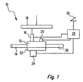
- an internal combustion engine bears the reference number 10 as a whole. It is typically operated on the four-stroke principle, that is to say that one working cycle comprises four cycles. Used is such an internal combustion engine, for example in motor vehicles. It comprises a combustion chamber 12, to which air is supplied via an intake pipe 14. Fuel is injected into the combustion chamber 12 through a high pressure injector 16. This is fed from a fuel rail 18, also referred to as a "rail", in which the fuel is supplied under very high pressure. The ignition of the fuel-air mixture formed in the combustion chamber 12 is effected by an ignition device 20, preferably a spark plug. By the expansion of the burning air-fuel mixture a piston 22 is moved. The operating state of the internal combustion engine 10, in particular the position of the piston 22, is detected by a sensor 24. The hot combustion exhaust gases are discharged through an exhaust pipe 26.
- the internal combustion engine 10 comprises a control and regulating device 28, to which the power requirement of a user is communicated by means of an accelerator pedal 30. Furthermore, the control and regulating device 28 still receives signals from the sensor 24. On the output side, it is u.a. connected to the injection valve 16 and the ignition system 20.
- the fuel In order to homogenize, i. To achieve the most uniform possible mixing of the fuel injected from the injection valve 16 into the combustion chamber 12 with the air sucked in through the intake pipe 14, the fuel is generally collected very early, i. already at the beginning of the downward movement of the piston 22 in the intake phase of the internal combustion engine 10, injected.
- the relevant angle of the crankshaft (not shown) of the internal combustion engine 10 is detected by the sensor 24 and forwarded a corresponding signal to the control and regulating device 28.
- the injection valve 16 is controlled by the control and regulating device 28 so that it opens and closes in pulses, wherein the opening time of the injection valve 16 0.5 ms does not exceed.
- the amount of fuel entering the combustion chamber 12 during an injection pulse, that is to say during a coherent opening time of the injection valve 16, should normally not exceed approximately 5 mm 3 . With such a pulse duration and such an amount of fuel injected per pulse, the penetration depth of the fuel in the combustion chamber 12 decreases so that the fuel no longer impacts the wall of the combustion chamber 12 opposite the injection valve 16.
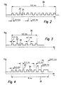
- FIGS. 2 to 7 different embodiments of possible pulse sequences for the fuel injection into the combustion chamber 12 are shown.
- the individual injection pulses carry the reference numeral 32, whereas the pauses between two injection pulses carry the reference numeral 34.
- the entire injection of a duty cycle of the internal combustion engine is indicated at 36.
- the time intervals between two pulses 32 over the duration of an injection are the same length and approximately 0.5 ms.
- the duration of an injection pulse 32 itself is about 0.3 ms.
- the duration of the total injection 36 is approximately 9.5 ms in the exemplary embodiment illustrated in FIG.
- a fuel quantity of a total of 60 mm 3 is injected during the injection 36 shown in FIG. 2.
- the time window available for injection is approximately 11 ms. The amount of fuel to be injected at full load of 60 mm 3 can thus be introduced into the combustion chamber 12 of the internal combustion engine 10 without problems.
- the embodiment shown in Fig. 3 is intended for an operating condition of the internal combustion engine 10, in which this at a speed of 5000 revolutions / min working in the partial load range.
- the time window available for injection 36 is approximately 9 ms long. With the six injection pulses 32 of 0.3 ms duration and pauses 34 of 0.7 ms duration results in a total duration of the injection of 5.5 ms at a partial load corresponding to the injection amount of 30 mm 3 .
- the intervals between the injection pulses can be shortened in an exemplary embodiment which is not illustrated.
- a time window for the injection of approximately 7.5 ms is available.
- twelve injection pulses suffice, each injecting approximately 5 mm 3 of fuel, and each spaced 0.33 ms apart from each other. The resulting total injection duration of 7.3 ms is well within the available time window.
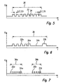
- the duration of the injection pulses 32 increases toward the end of the total injection 36.
- a procedure is indicated, for example, when the injection takes place not only during the intake phase but also during the compression phase of the internal combustion engine 10. Since the pressure in the combustion chamber 12 increases during the compression phase, the penetration depth decreases with a constant injection partial quantity or, with the same penetration depth, a larger injection partial quantity per injection pulse 32 can be selected.
- the duration of the Total Injection 36 is approximately 8 ms, with the duration of an injection pulse 32 increasing from 0.3 ms to 0.5, further to 0.66 and finally to 0.83 ms towards the end of the injection. It is also possible to increase the injection quantity toward the end of an injection 36 in that the duration of the pauses 34 between two injection pulses 32 is reduced. Such an embodiment is shown in FIG.
- FIG. 7 Embodiment in which within a working cycle of the internal combustion engine 10, two injections 36a and 36b are carried out, each of which in turn consists of individual injection pulses 32a and 32b with intervening pauses 34a and 34b.
Landscapes
- Engineering & Computer Science (AREA)
- Chemical & Material Sciences (AREA)
- Combustion & Propulsion (AREA)
- Mechanical Engineering (AREA)
- General Engineering & Computer Science (AREA)
- Electrical Control Of Air Or Fuel Supplied To Internal-Combustion Engine (AREA)
Claims (14)
- Procédé de gestion d'un moteur à combustion interne (10), en particulier d'un véhicule automobile, dans lequel de l'essence est injectée directement dans une chambre de combustion (12) du moteur à combustion interne (10) pendant une phase d'admission, au moyen d'un injecteur (16), avec au moins une injection (36) par cycle de travail,
caractérisé en ce qu'
une injection de carburant (36) pendant une phase d'admission comprend une pluralité de brèves impulsions d'injection (32) écartées les unes des autres dans le temps, au moins une impulsion étant suffisamment brève pour que l'essence injectée dans la chambre de combustion (12) pendant la phase d'admission ne rebondisse pas sur la paroi opposée à l'injecteur (16). - Procédé selon la revendication 1,
caractérisé en ce que
la quantité de carburant parvenant dans la chambre de combustion (12) lors d'une injection (36) est réglée au moins aussi par la durée des impulsions d'injection individuelles (32). - Procédé selon l'une des revendications précédentes,
caractérisé en ce que
la quantité de carburant parvenant dans la chambre de combustion (12) lors d'une injection (36) est réglée au moins aussi par le nombre d'impulsions d'injection individuelles (32). - Procédé selon l'une des revendications précédentes,
caractérisé en ce que
les impulsions d'injection (32) sont uniformément réparties sur la durée totale d'une injection (36). - Procédé selon l'une des revendications précédentes,
caractérisé en ce que
la durée des impulsions d'injection (32) ne varie pas sur la durée totale d'une injection (36). - Procédé selon l'une des revendications précédentes,
caractérisé en ce que
l'intervalle de temps (34) entre deux impulsions d'injection (32) varie sur la durée d'une injection (36). - Procédé selon l'une des revendications précédentes,
caractérisé en ce que
la durée d'une impulsion d'injection (32) varie, de préférence augmente, sur la durée totale d'une injection (36). - Procédé selon l'une des revendications précédentes,
caractérisé en ce qu'
à la fin d'une injection (36) on produit une impulsion d'injection unique (32b) qui dure plus longtemps que les impulsions d'injection précédentes (32a) de l'injection (36). - Procédé selon l'une des revendications précédentes,
caractérisé en ce qu'
à chaque impulsion d'injection (32), approximativement 5 mm3 de carburant sont injectés et/ou une impulsion d'injection (32) ne dure pas plus qu'environ 0,5 ms. - Procédé selon l'une des revendications précédentes,
caractérisé en ce que
plusieurs injections de carburant (36a, 36b) se produisent pour chaque cycle de travail, parmi lesquelles au moins l'une (36a, 36b) se compose également de plusieurs impulsions d'injection (32a, 32b). - Programme informatique,
caractérisé en ce qu'
il est programmé pour appliquer un procédé selon l'une des revendications précédentes. - Support de stockage électrique pour un dispositif de commande et/ou de régulation (28) d'un moteur à combustion interne (10),
caractérisé en ce qu'
il contient un programme informatique destiné à appliquer un procédé selon les revendications 1 à 10. - Dispositif de commande et/ou de régulation (28) pour un moteur à combustion interne (10),
caractérisé en ce qu'
il est programmé pour appliquer un procédé selon l'une des revendications 1 à 10. - Moteur à combustion interne (10), en particulier pour un véhicule automobile, comprenant un dispositif de commande et/ou de régulation (28),
caractérisé en ce que
le dispositif de commande et/ou de régulation est programmé pour appliquer un procédé selon l'une des revendications 1 à 10.
Applications Claiming Priority (3)
| Application Number | Priority Date | Filing Date | Title |
|---|---|---|---|
| DE10105755A DE10105755A1 (de) | 2001-02-08 | 2001-02-08 | Verfahren, Computerprogramm und Steuer- und/oder Regelgerät zum Betreiben einer Brennkraftmaschine sowie Brennkraftmaschine |
| DE10105755 | 2001-02-08 | ||
| PCT/DE2002/000394 WO2002063155A1 (fr) | 2001-02-08 | 2002-02-04 | Procede, programme informatique et appareil de commande ou de regulation pour l'exploitation d'un moteur a combustion interne, ainsi que moteur a combustion interne |
Publications (2)
| Publication Number | Publication Date |
|---|---|
| EP1364112A1 EP1364112A1 (fr) | 2003-11-26 |
| EP1364112B1 true EP1364112B1 (fr) | 2006-05-03 |
Family
ID=7673305
Family Applications (1)
| Application Number | Title | Priority Date | Filing Date |
|---|---|---|---|
| EP02706664A Expired - Lifetime EP1364112B1 (fr) | 2001-02-08 | 2002-02-04 | Procede, programme informatique et appareil de commande ou de regulation pour l'exploitation d'un moteur a combustion interne, ainsi que moteur a combustion interne |
Country Status (5)
| Country | Link |
|---|---|
| US (1) | US6912991B2 (fr) |
| EP (1) | EP1364112B1 (fr) |
| JP (1) | JP2004518070A (fr) |
| DE (3) | DE10105755A1 (fr) |
| WO (1) | WO2002063155A1 (fr) |
Cited By (1)
| Publication number | Priority date | Publication date | Assignee | Title |
|---|---|---|---|---|
| DE102006030213A1 (de) * | 2006-06-30 | 2008-01-03 | Fev Motorentechnik Gmbh | Homogenisiertes Einspritzverfahren |
Families Citing this family (23)
| Publication number | Priority date | Publication date | Assignee | Title |
|---|---|---|---|---|
| JP2002206446A (ja) * | 2001-01-10 | 2002-07-26 | Hitachi Ltd | 内燃機関及び内燃機関の燃料噴射制御装置 |
| DE10320848B4 (de) | 2003-05-09 | 2016-05-04 | Daimler Ag | Verfahren zum Betrieb einer fremdgezündeten Brennkraftmaschine |
| DE102004017989B4 (de) * | 2004-04-14 | 2019-03-28 | Daimler Ag | Verfahren zum Betrieb einer Brennkraftmaschine mit Kraftstoffdirekteinspritzung |
| US20070028899A1 (en) * | 2005-08-05 | 2007-02-08 | Jeffrey Allen | Fuel injection unit |
| US7458364B2 (en) | 2005-08-05 | 2008-12-02 | Scion-Sprays Limited | Internal combustion engine having a fuel injection system |
| GB2436593B (en) * | 2006-03-28 | 2008-02-20 | Scion Sprays Ltd | An internal combustion engine having a fuel injection system |
| CN101956621B (zh) * | 2005-08-05 | 2013-12-25 | 罗伯特.博世有限公司 | 用于内燃机的燃料喷射系统 |
| JP2007100623A (ja) * | 2005-10-06 | 2007-04-19 | Denso Corp | ディーゼル機関の燃料噴射制御装置 |
| US7360522B2 (en) * | 2006-07-25 | 2008-04-22 | General Electric Company | System and method for operating a turbo-charged engine |
| US7770813B2 (en) | 2006-10-11 | 2010-08-10 | Gm Global Technology Operations, Inc. | Spray penetration control method |
| AT502972B1 (de) * | 2006-12-07 | 2008-06-15 | Avl List Gmbh | Verfahren zum betreiben einer brennkraftmaschine |
| DE102010011105A1 (de) * | 2010-03-11 | 2011-09-15 | Daimler Ag | Verfahren zum Betrieb einer fremdgezündeten Brennkraftmaschine |
| JP5011413B2 (ja) * | 2010-03-17 | 2012-08-29 | 日立オートモティブシステムズ株式会社 | 筒内直接燃料噴射方式内燃機関の制御装置 |
| DE102010014824B4 (de) * | 2010-04-13 | 2013-09-26 | Continental Automotive Gmbh | Verfahren zum Betreiben einer Brennkraftmaschine und Brennkraftmaschine |
| JP5809796B2 (ja) * | 2010-11-30 | 2015-11-11 | 日立オートモティブシステムズ株式会社 | 内燃機関の燃料噴射制御装置 |
| WO2015024747A1 (fr) * | 2013-08-19 | 2015-02-26 | Robert Bosch Gmbh | Procédé de commande d'un système d'injection de carburant et dispositif correspondant |
| WO2015028251A1 (fr) * | 2013-08-26 | 2015-03-05 | Robert Bosch Gmbh | Procédé de commande d'un système d'injection de carburant d'un moteur à combustion interne dont l'injecteur de carburant est alimenté par gravité |
| WO2015028252A1 (fr) * | 2013-08-29 | 2015-03-05 | Robert Bosch Gmbh | Procédé de commande d'un système d'injection de carburant d'un moteur à combustion interne dont l'injecteur de carburant est alimenté par la gravité |
| JP2018193915A (ja) * | 2017-05-17 | 2018-12-06 | マツダ株式会社 | ディーゼルエンジンの燃料噴射制御方法及び燃料噴射制御装置 |
| DE102019214230B4 (de) * | 2019-09-18 | 2022-02-10 | Vitesco Technologies GmbH | Verfahren zur Regelung der Gesamt-Einspritzmasse bei einer Mehrfacheinspritzung |
| DE102019219541B4 (de) | 2019-12-13 | 2021-08-05 | Vitesco Technologies GmbH | Verfahren und Motorsteuerung zur Mehrfacheinspritzung mit Mengenkorrektur für einen Verbrennungsmotor |
| DE102021211658A1 (de) | 2021-10-15 | 2023-04-20 | Hitachi Astemo, Ltd. | Verfahren und vorrichtung zum steuern der kraftstoffeinspritzung einer brennkraftmaschine |
| DE102022106869A1 (de) | 2022-03-23 | 2023-09-28 | Volkswagen Aktiengesellschaft | Verfahren zum Betreiben einer mehrfach direkteinspritzenden Brennkraftmaschine und massenbasierter Umschaltung der Anzahl von Einspritzungen |
Family Cites Families (9)
| Publication number | Priority date | Publication date | Assignee | Title |
|---|---|---|---|---|
| US4579096A (en) * | 1983-12-08 | 1986-04-01 | Toyota Jidosha Kabushiki Kaisha | Diesel fuel injection pump with electromagnetic fuel spilling valve having pilot valve providing high responsiveness |
| DE3936619A1 (de) * | 1989-11-03 | 1991-05-08 | Man Nutzfahrzeuge Ag | Verfahren zum einspritzen eines brennstoffes in einen brennraum einer luftverdichtenden, selbstzuendenden brennkraftmaschine, sowie vorrichtungen zur durchfuehrung dieses verfahrens |
| US5168846A (en) * | 1991-06-14 | 1992-12-08 | Paul Marius A | Rotary engine with variable displacement |
| EP0786592B1 (fr) * | 1996-01-29 | 2002-05-02 | Wärtsilä Schweiz AG | Méthode de dispositif d'injection de carburant dans un moteur à pistons à combustion interne |
| KR100354216B1 (ko) * | 1996-08-29 | 2003-02-20 | 미쯔비시 지도샤 고교 가부시끼가이샤 | 연료분사장치 |
| DE19639172C2 (de) | 1996-09-24 | 2001-11-08 | Siemens Ag | Kraftstoff-Direkteinspritzverfahren für eine Dieselbrennkraftmaschine |
| JP3189734B2 (ja) | 1996-12-19 | 2001-07-16 | 三菱自動車工業株式会社 | 火花点火式筒内噴射型内燃機関 |
| IT1308412B1 (it) * | 1999-03-05 | 2001-12-17 | Fiat Ricerche | Metodo di controllo della combustione di un motore diesel ad iniezionediretta tramite l'attuazione di iniezioni multiple mediante un sistema |
| US6705277B1 (en) * | 2000-07-13 | 2004-03-16 | Caterpillar Inc | Method and apparatus for delivering multiple fuel injections to the cylinder of an engine wherein the pilot fuel injection occurs during the intake stroke |
-
2001
- 2001-02-08 DE DE10105755A patent/DE10105755A1/de not_active Ceased
-
2002
- 2002-02-04 WO PCT/DE2002/000394 patent/WO2002063155A1/fr not_active Ceased
- 2002-02-04 EP EP02706664A patent/EP1364112B1/fr not_active Expired - Lifetime
- 2002-02-04 US US10/467,527 patent/US6912991B2/en not_active Expired - Fee Related
- 2002-02-04 JP JP2002562873A patent/JP2004518070A/ja active Pending
- 2002-02-04 DE DE10290397T patent/DE10290397D2/de not_active Expired - Lifetime
- 2002-02-04 DE DE50206659T patent/DE50206659D1/de not_active Expired - Lifetime
Cited By (1)
| Publication number | Priority date | Publication date | Assignee | Title |
|---|---|---|---|---|
| DE102006030213A1 (de) * | 2006-06-30 | 2008-01-03 | Fev Motorentechnik Gmbh | Homogenisiertes Einspritzverfahren |
Also Published As
| Publication number | Publication date |
|---|---|
| DE10290397D2 (de) | 2004-01-08 |
| DE50206659D1 (de) | 2006-06-08 |
| DE10105755A1 (de) | 2002-08-29 |
| JP2004518070A (ja) | 2004-06-17 |
| WO2002063155A1 (fr) | 2002-08-15 |
| EP1364112A1 (fr) | 2003-11-26 |
| US20040040534A1 (en) | 2004-03-04 |
| US6912991B2 (en) | 2005-07-05 |
Similar Documents
| Publication | Publication Date | Title |
|---|---|---|
| EP1364112B1 (fr) | Procede, programme informatique et appareil de commande ou de regulation pour l'exploitation d'un moteur a combustion interne, ainsi que moteur a combustion interne | |
| DE102004053123B4 (de) | Kompressionszündungsbrennkraftmaschine | |
| DE602004012478T2 (de) | Vorrichtung und Verfahren zur Steuerung von Mehrfachfacheinspritzung und variablen Ventilsteuerzeiten in einer direkteinspritzenden Brennkraftmaschine | |
| EP1203145B1 (fr) | Procede pour faire fonctionner un moteur a combustion interne | |
| DE112015002732B4 (de) | Steuervorrichtung für Verbrennungsmotor | |
| DE112006002990T5 (de) | Verfahren und Vorrichtung zum Betreiben einer funkengezündeten Brennkraftmaschine mit Direkteinspritzung | |
| DE112009000256T5 (de) | Verfahren und Vorrichtung zum Steuern eines Moduswechsels in einem Verbrennungsmotor mit Funkenzündung und Direkteinspritzung | |
| DE102007013119A1 (de) | Einspritzverfahren und zugehörige Verbrennungskraftmaschine | |
| DE10111928B4 (de) | Verfahren zum anlasserfreien Starten einer mehrzylindrigen Brennkraftmaschine | |
| DE10242227A1 (de) | Verfahren zum Betrieb einer Brennkraftmaschine mit Kraftstoffdirekteinspritzung | |
| WO2005103468A1 (fr) | Procede permettant de faire fonctionner un moteur a combustion interne dans la phase de post-demarrage a de faibles temperatures | |
| DE19815266B4 (de) | Verfahren zur Einspritzung von Kraftstoff in eine Brennkraftmaschine | |
| DE102012107714A1 (de) | Steuersystem für ein Verbrennungssystem | |
| DE102006035466B4 (de) | Selbstzündungsmaschinensteuergerät, das ein gewünschtes Ausgabemoment sicherstellt | |
| DE102010029935B4 (de) | Verfahren und Vorrichtung zum Zuführen von Kraftstoff in einem Verbrennungsmotor | |
| DE102010038779A1 (de) | Verfahren zum Betreiben einer Brennkraftmaschine mit mehreren Brennräumen und Brennkraftmaschine mit mehreren Brennräumen | |
| WO1999020882A1 (fr) | Procede de demarrage d'un moteur a combustion interne | |
| DE102012212924A1 (de) | Kraftstoffsteuerungssystem für eine Brennkraftmaschine | |
| DE60133064T2 (de) | Brennkraftmaschine mit externer Unterstützung für stabile Selbstzündung | |
| EP1703112A1 (fr) | Procédé de chauffage d'un catalyseur d'un moteur à combustion interne | |
| WO2000058618A1 (fr) | Procede permettant de faire fonctionner un moteur a combustion interne | |
| DE10148651C1 (de) | Verfahren zum Betreiben einer Brennkraftmaschine mit Abgasrückführung und Kraftstoffeinspritzung | |
| DE69213583T2 (de) | Schichtladungsbrennkraftmaschine mit Einspritzzeitpunktsteuerung | |
| DE10333261B4 (de) | Verfahren zum Betrieb eines direkt einspritzenden Ottomotors sowie direkt einspritzender Ottomotor | |
| EP1436495A1 (fr) | Procede, programme informatique et appareil de commande et / ou de regulation permettant de faire fonctionner un moteur a combustion interne a injection directe |
Legal Events
| Date | Code | Title | Description |
|---|---|---|---|
| PUAI | Public reference made under article 153(3) epc to a published international application that has entered the european phase |
Free format text: ORIGINAL CODE: 0009012 |
|
| 17P | Request for examination filed |
Effective date: 20030908 |
|
| AK | Designated contracting states |
Kind code of ref document: A1 Designated state(s): AT BE CH CY DE DK ES FI FR GB GR IE IT LI LU MC NL PT SE TR |
|
| AX | Request for extension of the european patent |
Extension state: AL LT LV MK RO SI |
|
| 17Q | First examination report despatched |
Effective date: 20050209 |
|
| GRAP | Despatch of communication of intention to grant a patent |
Free format text: ORIGINAL CODE: EPIDOSNIGR1 |
|
| GRAS | Grant fee paid |
Free format text: ORIGINAL CODE: EPIDOSNIGR3 |
|
| GRAA | (expected) grant |
Free format text: ORIGINAL CODE: 0009210 |
|
| AK | Designated contracting states |
Kind code of ref document: B1 Designated state(s): DE FR IT |
|
| PG25 | Lapsed in a contracting state [announced via postgrant information from national office to epo] |
Ref country code: IT Free format text: LAPSE BECAUSE OF FAILURE TO SUBMIT A TRANSLATION OF THE DESCRIPTION OR TO PAY THE FEE WITHIN THE PRESCRIBED TIME-LIMIT;WARNING: LAPSES OF ITALIAN PATENTS WITH EFFECTIVE DATE BEFORE 2007 MAY HAVE OCCURRED AT ANY TIME BEFORE 2007. THE CORRECT EFFECTIVE DATE MAY BE DIFFERENT FROM THE ONE RECORDED. Effective date: 20060503 |
|
| REF | Corresponds to: |
Ref document number: 50206659 Country of ref document: DE Date of ref document: 20060608 Kind code of ref document: P |
|
| ET | Fr: translation filed | ||
| PLBE | No opposition filed within time limit |
Free format text: ORIGINAL CODE: 0009261 |
|
| STAA | Information on the status of an ep patent application or granted ep patent |
Free format text: STATUS: NO OPPOSITION FILED WITHIN TIME LIMIT |
|
| 26N | No opposition filed |
Effective date: 20070206 |
|
| PGFP | Annual fee paid to national office [announced via postgrant information from national office to epo] |
Ref country code: IT Payment date: 20140224 Year of fee payment: 13 Ref country code: FR Payment date: 20140218 Year of fee payment: 13 |
|
| PGFP | Annual fee paid to national office [announced via postgrant information from national office to epo] |
Ref country code: DE Payment date: 20150424 Year of fee payment: 14 |
|
| REG | Reference to a national code |
Ref country code: FR Ref legal event code: ST Effective date: 20151030 |
|
| PG25 | Lapsed in a contracting state [announced via postgrant information from national office to epo] |
Ref country code: IT Free format text: LAPSE BECAUSE OF NON-PAYMENT OF DUE FEES Effective date: 20150204 |
|
| PG25 | Lapsed in a contracting state [announced via postgrant information from national office to epo] |
Ref country code: FR Free format text: LAPSE BECAUSE OF NON-PAYMENT OF DUE FEES Effective date: 20150302 |
|
| REG | Reference to a national code |
Ref country code: DE Ref legal event code: R119 Ref document number: 50206659 Country of ref document: DE |
|
| PG25 | Lapsed in a contracting state [announced via postgrant information from national office to epo] |
Ref country code: DE Free format text: LAPSE BECAUSE OF NON-PAYMENT OF DUE FEES Effective date: 20160901 |