EP1364840A1 - Coussin gonflable pour conducteur ou passager - Google Patents
Coussin gonflable pour conducteur ou passager Download PDFInfo
- Publication number
- EP1364840A1 EP1364840A1 EP03090146A EP03090146A EP1364840A1 EP 1364840 A1 EP1364840 A1 EP 1364840A1 EP 03090146 A EP03090146 A EP 03090146A EP 03090146 A EP03090146 A EP 03090146A EP 1364840 A1 EP1364840 A1 EP 1364840A1
- Authority
- EP
- European Patent Office
- Prior art keywords
- airbag
- gas bag
- sections
- occupant
- gap
- Prior art date
- Legal status (The legal status is an assumption and is not a legal conclusion. Google has not performed a legal analysis and makes no representation as to the accuracy of the status listed.)
- Granted
Links
- 210000003127 knee Anatomy 0.000 claims description 4
- 239000012528 membrane Substances 0.000 claims description 2
- 230000001012 protector Effects 0.000 claims description 2
- 230000007704 transition Effects 0.000 claims description 2
- 239000007789 gas Substances 0.000 description 73
- 230000004048 modification Effects 0.000 description 8
- 238000012986 modification Methods 0.000 description 8
- 230000014759 maintenance of location Effects 0.000 description 6
- 230000000694 effects Effects 0.000 description 5
- 238000000034 method Methods 0.000 description 5
- 230000008569 process Effects 0.000 description 5
- 239000004744 fabric Substances 0.000 description 4
- 230000001681 protective effect Effects 0.000 description 4
- 238000007373 indentation Methods 0.000 description 3
- 230000035515 penetration Effects 0.000 description 3
- 208000027418 Wounds and injury Diseases 0.000 description 2
- 230000006378 damage Effects 0.000 description 2
- 238000007654 immersion Methods 0.000 description 2
- 208000014674 injury Diseases 0.000 description 2
- 230000003187 abdominal effect Effects 0.000 description 1
- 230000006978 adaptation Effects 0.000 description 1
- 238000010304 firing Methods 0.000 description 1
- 230000009467 reduction Effects 0.000 description 1
- 230000035882 stress Effects 0.000 description 1
- 230000008646 thermal stress Effects 0.000 description 1
- 210000000689 upper leg Anatomy 0.000 description 1
Images




Classifications
-
- B—PERFORMING OPERATIONS; TRANSPORTING
- B60—VEHICLES IN GENERAL
- B60R—VEHICLES, VEHICLE FITTINGS, OR VEHICLE PARTS, NOT OTHERWISE PROVIDED FOR
- B60R21/00—Arrangements or fittings on vehicles for protecting or preventing injuries to occupants or pedestrians in case of accidents or other traffic risks
- B60R21/02—Occupant safety arrangements or fittings, e.g. crash pads
- B60R21/16—Inflatable occupant restraints or confinements designed to inflate upon impact or impending impact, e.g. air bags
- B60R21/23—Inflatable members
- B60R21/231—Inflatable members characterised by their shape, construction or spatial configuration
- B60R21/233—Inflatable members characterised by their shape, construction or spatial configuration comprising a plurality of individual compartments; comprising two or more bag-like members, one within the other
-
- B—PERFORMING OPERATIONS; TRANSPORTING
- B60—VEHICLES IN GENERAL
- B60R—VEHICLES, VEHICLE FITTINGS, OR VEHICLE PARTS, NOT OTHERWISE PROVIDED FOR
- B60R21/00—Arrangements or fittings on vehicles for protecting or preventing injuries to occupants or pedestrians in case of accidents or other traffic risks
- B60R21/02—Occupant safety arrangements or fittings, e.g. crash pads
- B60R21/16—Inflatable occupant restraints or confinements designed to inflate upon impact or impending impact, e.g. air bags
- B60R21/23—Inflatable members
- B60R21/231—Inflatable members characterised by their shape, construction or spatial configuration
- B60R21/2334—Expansion control features
- B60R21/2338—Tethers
-
- B—PERFORMING OPERATIONS; TRANSPORTING
- B60—VEHICLES IN GENERAL
- B60R—VEHICLES, VEHICLE FITTINGS, OR VEHICLE PARTS, NOT OTHERWISE PROVIDED FOR
- B60R21/00—Arrangements or fittings on vehicles for protecting or preventing injuries to occupants or pedestrians in case of accidents or other traffic risks
- B60R21/02—Occupant safety arrangements or fittings, e.g. crash pads
- B60R21/16—Inflatable occupant restraints or confinements designed to inflate upon impact or impending impact, e.g. air bags
- B60R21/23—Inflatable members
- B60R21/231—Inflatable members characterised by their shape, construction or spatial configuration
- B60R2021/23169—Inflatable members characterised by their shape, construction or spatial configuration specially adapted for knee protection
-
- B—PERFORMING OPERATIONS; TRANSPORTING
- B60—VEHICLES IN GENERAL
- B60R—VEHICLES, VEHICLE FITTINGS, OR VEHICLE PARTS, NOT OTHERWISE PROVIDED FOR
- B60R21/00—Arrangements or fittings on vehicles for protecting or preventing injuries to occupants or pedestrians in case of accidents or other traffic risks
- B60R21/02—Occupant safety arrangements or fittings, e.g. crash pads
- B60R21/16—Inflatable occupant restraints or confinements designed to inflate upon impact or impending impact, e.g. air bags
- B60R21/23—Inflatable members
- B60R21/231—Inflatable members characterised by their shape, construction or spatial configuration
- B60R21/2334—Expansion control features
- B60R21/2338—Tethers
- B60R2021/23386—External tether means
-
- B—PERFORMING OPERATIONS; TRANSPORTING
- B60—VEHICLES IN GENERAL
- B60R—VEHICLES, VEHICLE FITTINGS, OR VEHICLE PARTS, NOT OTHERWISE PROVIDED FOR
- B60R21/00—Arrangements or fittings on vehicles for protecting or preventing injuries to occupants or pedestrians in case of accidents or other traffic risks
- B60R21/02—Occupant safety arrangements or fittings, e.g. crash pads
- B60R21/06—Safety nets, transparent sheets, curtains, or the like, e.g. between occupants and glass
- B60R21/08—Safety nets, transparent sheets, curtains, or the like, e.g. between occupants and glass automatically movable from an inoperative to an operative position, e.g. in a collision
Definitions
- the invention relates to a driver or front passenger airbag for motor vehicles after the Preamble of claim 1.
- Such an airbag is used to protect a motor vehicle occupant in a so-called front crash, in which a vehicle is head-on with an obstacle collides, in particular to avoid a collision of one of the front Vehicle occupants with the windshield, the steering wheel or the instrument panel.
- the gas bag of a generic driver or passenger airbags has at least two such separate gas bag sections that the means of a Gas generator inflated airbag on its occupant to be protected facing front with a running between the gas bag sections Gap is provided and the gas bag sections exclusively on the to protective occupant facing away from each other are connected.
- an airbag for an occupant protection device in Known motor vehicles which is inflatable by means of a gas generator and the outer shell in the inflated state on its to be protected occupant assigned enveloping surface forms a gap into which the occupant to be protected in an oop case when inflating the airbag with a gas bag facing Part of the body can penetrate, the gap is spread to the collision of the To mitigate occupants with the associated envelope of the airbag in an oop case.
- means e.g. in the form of a sheet-like element, be provided to the separated by the gap gas bag sections against each other Tense so that the gas bag after inflation for a normal position occupant the same protection forms as a gas bag without a gap. It is however, by arranging and forming the sheet-like element ensures that a out of its normal sitting position, towards the air bag module Prevented occupant (corresponding to the so-called oop case) during inflation of the Airbag can penetrate into the gas bag gap.
- a disadvantage of the known gas bags for an airbag module is that they despite reduced mechanical load on the occupant to be protected in an oop case too can cause thermal stress on the occupant to be protected, if this with hot tissue parts of the airbag in contact, i. with tissue parts of the Airbag cover by the hot gases used to inflate the airbag were heated.
- the invention is based on the problem, a driver or passenger airbag to improve the aforementioned type on.
- the gap in the region of the front side of the airbag is so from a plane element bridged that the occupant to be protected in a collision in Direction to the front of the airbag not possible through the two Airbag sections, but is collected by the sheet-like element. It can quite a body part of the occupant (possibly together with the planar element) a Piece into the gap; the inmate should not be on the plane Element over, i.e. without being caught by this, in the gap altogether penetration.
- the gas bag designed according to the invention on the one hand two Gas bag sections, which at the front of the airbag through a gap are completely separated from each other (as known from DE 100 33 937 A1) and on the other hand, a planar element which bridges the gap such that the Protective inmate can not penetrate into these, can achieve that Retaining effect for the protection of a vehicle occupant essentially by the planar element is taken over and the two inflatable airbag sections in essential only serve to tighten the sheet-like element. This allows the to Protection of the vehicle occupant required retention effect can be achieved without that the occupant is in contact with the shell of the airbag and thus possibly with hot tissue parts device.
- the planar element extends immediately before the upper body and the head of the occupant to be protected facing the front end of the airbag, ie directly along the front of the airbag, leaving the gap - from the head and torso of the protected Inmates ago seen - is completely covered by the sheet-like element.
- the planar element with respect to the Head and upper body of the vehicle occupant to be protected front facing The end (the front) of the airbag slightly backwards, towards the head and offset the upper body of the vehicle occupant rear side of the airbag, so that a part of the gap formed between the gas bag sections - from the head and upper body of the vehicle occupant seen ago - in front of the sheet-like element runs.
- the vehicle occupant penetrates the surface before the impact Element first piece by piece in the area not covered by the sheet element of the gap between the two gas bag sections, before passing through the flat Element is caught.
- the inventively designed airbag for a driver or passenger airbag is on each of the separated by the gap gas bag sections at least attached a point and in this case preferably has a total of at least three Attachment points on. This ensures that the sheet-like element immovable (with respect to the airbag) is fixed to the gas bag.
- the planar element When inflating the airbag, the planar element is tightened, so that it required retention effect, and at the same time by the Gap separated from each other airbag sections braced against each other.
- planar element bridges the gap such that the occupant in an impact in Direction to the front of the airbag (and also in a so-called oop case) is captured by the planar element, so this as the actual Retaining element is used.
- the occupant is accordingly preferably through an area of the planar element caught and held back, behind which runs at least part of the gap, so that a direct contact of the occupant with the airbag cover avoided as possible becomes.
- the airbag sections are preferably designed and arranged such that they when inflating the airbag - seen by the occupant to be protected - each in a direction next to the upper body of the occupant to be protected deploy, so that the gap in the inflated airbag substantially in Longitudinal direction of the upper body of the occupant to be protected, i. parallel to Spine of the corresponding occupant, extends.
- the planar element itself can on the one hand be membrane-like, e.g. as a tissue part, or on the other hand be designed as a network.
- those seams are suitable, which at the same time for connecting various parts of the airbag envelope, e.g. a sub and serve a top plate of the airbag cover.
- the gas bag has exactly two through the Gassackabriske separated from each other on the inflated state in the Cross section are arranged substantially V-shaped.
- Gas bag sections provided in the inflated state substantially are arranged in a star shape.
- FIGS. 1 a and 1 d to 1 g an airbag 1 is shown whose airbag cover 10 two on the back R of the airbag 1 by a channel 13 in one piece with each other Connected airbag sections 11, 12, which on the front V of the Airbag 1 form a gap formed by a sheet-like element 2 in the form of a Membrane or a tissue part is bridged.
- the two airbag sections 11, 12 are completely separated from each other on the front side V of the airbag 1, i. the gap 15 extends through the entire gas bag, so that the two Airbag sections 11, 12 pivoted about the connecting channel 13 to each other could be if they were not held together by the planar element 2 would.
- the sheet 2 is along its outer edge 20 with each of the sewn on both airbag sections 11, 12, in such a way that in the inflated Condition of the airbag 1, the planar element 2 is streamlined and at the same time the two, in cross-section a V forming airbag sections 11, 12 braced against each other.
- FIG. 1b shows the gas bag from FIG. 1a in the inflated state in one Motor vehicle.
- the gas bag is in this case part of a within the dashboard A of the motor vehicle arranged passenger airbag module and extends in inflated state between the dashboard A, the windshield S and the too protective occupants l.
- the back R of the airbag is together with the remaining components of the airbag module, namely a gas generator for inflation of the airbag and a module housing for receiving airbag and Gas generator on the dashboard A set.
- the front V of the airbag is the upper body O and the head K of the occupant to be protected l faces, namely such that the occupant to be protected l to achieve the desired Retention with his head K and his upper body O on the flat element 2 hits, as shown with reference to Figure 1c, the impact of the vehicle occupant l with his head K and his upper body O on the from the gas bag 1 and the flat Element 2 existing airbag shows.
- the gap 15 extends between the two airbag sections 11, 12, so that an immediate collision of the head K and the upper body O of the vehicle occupant l is avoided as possible with the shell 10 of the airbag 1.
- this allows Configuration a self-centering of the head K and upper body O of the occupant l at an off-center impact on the sheet-like element 2.
- the sheet-like element 2 to tighten so that it can develop the desired retention effect.
- the gas bag sections 11, 12 sufficiently yielding, because that to inflate the Airbag 1 gas used immediately after deployment of the airbag 1 immediately is drained again, so that the sheet-like element 2 also in the streamlined state the impact of the vehicle occupant l is still sufficiently deformed to injury to avoid the vehicle occupant I, which in a too rigid clamping of the flat element 2 could occur.
- FIG. 2 a shows the upper or lower plate of an airbag 1 of FIG. 1 a To 1g illustrated type forming fabric part 100.
- the shell of the airbag 1 is made of two identical fabric parts 100 connected to one another along a seam according to FIG. 2a.
- Each of the two, the upper and lower plate forming tissue parts 100 each has two integrally connected elliptical sections 110, 120, so that from the fabric parts, a gas bag 1 with two Airbag sections 11, 12 can form according to Figures 1a to 1g.
- FIG. 2b shows a schematic side view of one of two fabric parts 100 According to Figure 2a existing gas bag 1 in the inflated state in one Motor vehicle, wherein the gas bag 1 is part of a in the dashboard of the Is arranged passenger car airbag module motor vehicle and by a in the Dashboard arranged gas generator G is inflatable. In the inflated state The gas bag 1 extends from the vehicle occupant (front passenger) to be protected seen in front of the dashboard A and below the windscreen S.
- Figure 2c shows a front view of an inflated, from the two tissue parts 100 according to Figure 2a existing airbag, wherein the two airbag sections 11, 12 on the front of the airbag facing the occupant to be protected are separated by a gap, which by a planar element. 2 is completely covered, and wherein the sheet-like element 2 along its edge 20th with each of the airbag sections 11, 12 is sewn.
- FIG. 2 d shows the gas bag 1 while it is being inflated out of the module housing M of a passenger airbag module unfolds.
- the two on the front V the gas bag 1 by a gap 15 separate gas bag sections 11, 12 remain as shown by the side view of the fully inflated Airbag in Figure 2e is clear, essentially at the lateral edge region of the Upper body O of the vehicle occupant to be protected l.
- the central area of the Upper body O central chest and abdominal area as well as head K) is the areal Element 2 associated with the inflating in a direction c frontal on the moving occupant moves and that through the two airbag sections 11, 12th is streamlined.
- the contact forces F are further indicated, which occur when in the Unfolding of the airbag, the two airbag sections 11, 12 in the region of the gap 15th touch.
- the forces F have the effect of the gas bag sections 11, 12 apart press, and lead to a tightening of the sheet-like element 2.
- the in the flat Element 2 occurring stress is due to the dimension of the gap 15th bridging area of the sheet-like element 2 influenced.
- the gap 15 bridging region of the sheet-like element 2 (corresponding to a greater distance between the attachment points of the sheet-like element 2 on both sides of the gap 15 and thus a larger width of the gap 15) does not occur only one lower voltage, but the airbag sections 11, 12 unfold more laterally outwards.
- the dimension of the planar element 2 thus also controls the Arrangement of the airbag sections 11, 12 of the fully inflated airbag.
- FIG. 3 a shows in greater detail the inside of a module housing M Passenger airbag module arranged gas bag 1 from Figures 1a to 2e, wherein the in Pleated airbag 1 surrounds a gas generator G.
- Figure 3b shows in greater detail the beginning of the deployment process of the airbag 1 out of the module housing M during inflation by means of a gas generator G, according to the schematic representation of Figure 2d.
- the References to Figure 2d it is also recognizable that for fixing the flat element 2 at the airbag sections 11, 12, the seam N is used, the for the connection of the two tissue parts (see Figure 2a), from which the shell of the Airbag 1 consists.
- FIG. 3c shows in greater detail a representation of the device G by means of the gas generator fully inflated and fully out of the module housing M out Airbag, according to the schematic representation in Figure 2e, on the Explanation for further details is referenced.
- FIG. 4 a shows a representation of the gas bag 1 folded in a module housing M corresponding to Figure 3a, but with a vehicle occupant l with his upper body O and his head K is located very close to the module housing M. This matches with a so-called oop case in which the vehicle occupant is out of his normal Sitting position out in the direction of the airbag module is prevented.
- Figures 4b and 4c show the gas bag 1 at the beginning of the deployment process as well as in the fully inflated state, as shown in the Figures 3b and 3c, but with the projecting in the direction of the airbag module Vehicle occupant l affects the deployment process of the airbag 1. Based on FIGS. 4b and 4c clearly show that the two airbag sections 11, 12 pass through the early immersion of the occupant l in the area between the two Airbag sections 11, 12 substantially laterally adjacent to the upper body O and the Develop head K of the vehicle occupant 1 to be protected, so that an immediate Ansch manen the vehicle occupant I is prevented in the oop case.
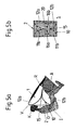
- FIG. 5a and 5b is a modification of the previous figures shown embodiment of a gas bag 1, in which the two Side airbag sections 11a, 11b on the one hand and 12a, 12b on the other hand in each case two subsections 11a and 11b and 12a and 12b are divided, so that the gas bag in a front view according to Figure 5b has a substantially star-shaped contour, and in addition to the slot 15, the two airbag sections 11a, 11b on the one hand and 12a, 12b on the other hand separates from each other, two additional column 16a, 16b are formed, each of the subsections 11a, 11 and 12a, 12b from each other separate.
- planar element 2 formed as a network.
- this embodiment is correct in its function with that explained with reference to the figures 1a to 4c.
- Figures 6a and 6b show an embodiment of a gas bag 1, wherein in Difference to the embodiment according to Figures 1a to 4c, the two Airbag sections 11, 12 not only by one of the sheet-like element. 2 covered gap 15 are separated from each other, but also on their Top of a bulge 16 below the windshield S of a motor vehicle exhibit.
- the two have Airbag sections 11, 12 additionally on its front side a bulge 17, i. a recess extending in the direction of the rear side R of the airbag 1.
- Figure 8 shows a modification of the embodiment of Figures 6a and 6b, at the planar element 2 is not directly on the front side V of the airbag. 1 extends and thus formed between the two airbag sections 11, 12 Gap (15) seen from the head K of the vehicle occupant L ago not completely covered. Rather, the sheet-like element 2 extends from the front side V of the airbag 1 Her in a transition region between the front V and the back R of Airbag 1, so that the head K and upper body O facing area of the between the airbag sections 11, 12 formed gap (15) not through the surface element 2 is covered.
- the vehicle occupant l dives a crash case on the front side V of the airbag assembly with his head K and his upper body O first a little way into the area between the two Airbag sections 11, 12 (see Figure 6b), before passing through the gap between these two airbag sections bridging planar element. 2 is caught.
- the described arrangement of the sheet-like element 2 is in particular by the additional bulge 16 of the airbag 1 allows the is partially limited by the sheet-like element 2.
- the gas bag arrangement shown in Figure 8 characterized from that the sheet-like element 2 on the front side V of the airbag 1 not directly on the head K and upper body O of the vehicle occupant I. facing the front end, but towards this front end Piece is offset far to the back R of the airbag 1.
- the flat element 2 thereby bridges only those areas of the between the airbag sections formed gap, the - from the head K and upper body O of the vehicle occupant L ago seen - lie behind the sheet-like element 2. Accordingly, the dives Vehicle occupant l in a crash-related movement towards the front V of the airbag 1 with his head K or upper body O first in the front of the planar element 2 lying areas of said gap, before passing through the flat element 2 is caught.
- FIG. 9 shows a further modification of the airbag arrangement from FIGS. 6a and 6b 6b, a difference being that the additional bulge 18 of the Airbag 1 the knee and thigh area of the occupant I to be protected (and not as in Figure 6a of the windshield S of the vehicle) faces.
- the gas bag 1 shown in FIG. 9 is formed and is set up to fix its rear end in the lower part of the Dashboard A of a motor vehicle, so that the airbag 1 in the area of his back end forms a knee protector for the vehicle occupants l, so one Gas bag section, which in a crash case as a retaining element for the knee the vehicle occupant serves.
Landscapes
- Engineering & Computer Science (AREA)
- Mechanical Engineering (AREA)
- Air Bags (AREA)
Applications Claiming Priority (2)
| Application Number | Priority Date | Filing Date | Title |
|---|---|---|---|
| DE10224138A DE10224138A1 (de) | 2002-05-24 | 2002-05-24 | Fahrer- oder Beifahrerairbag |
| DE10224138 | 2002-05-24 |
Publications (2)
| Publication Number | Publication Date |
|---|---|
| EP1364840A1 true EP1364840A1 (fr) | 2003-11-26 |
| EP1364840B1 EP1364840B1 (fr) | 2008-11-05 |
Family
ID=29285708
Family Applications (1)
| Application Number | Title | Priority Date | Filing Date |
|---|---|---|---|
| EP03090146A Expired - Lifetime EP1364840B1 (fr) | 2002-05-24 | 2003-05-16 | Coussin gonflable pour conducteur ou passager |
Country Status (4)
| Country | Link |
|---|---|
| US (1) | US6913283B2 (fr) |
| EP (1) | EP1364840B1 (fr) |
| JP (1) | JP3836818B2 (fr) |
| DE (2) | DE10224138A1 (fr) |
Cited By (9)
| Publication number | Priority date | Publication date | Assignee | Title |
|---|---|---|---|---|
| EP1650087A3 (fr) * | 2004-10-21 | 2007-01-03 | Takata Corporation | Dispositif d'airbag |
| WO2007022758A1 (fr) | 2005-08-25 | 2007-03-01 | Takata-Petri Ag | Module sac gonflable dote d'un sac a gaz destine au conducteur ou au passager |
| WO2007039061A1 (fr) * | 2005-10-04 | 2007-04-12 | Autoliv Development Ab | Ensemble coussin gonflable |
| WO2009003854A3 (fr) * | 2007-07-04 | 2009-02-19 | Takata Petri Ag | Airbag pour motocyclette, motocyclette équipée d'un tel airbag, procédé pour la fabrication d'un airbag de motocyclette et procédé de protection d'un conducteur d'une motocyclette en cas d'accident |
| WO2009056307A1 (fr) * | 2007-11-02 | 2009-05-07 | Daimler Ag | Système de sécurité pour des occupants d'un véhicule avec des éléments à absorption d'énergie, et procédé de soutien d'un occupant |
| CN100575153C (zh) * | 2004-11-12 | 2009-12-30 | 高田-彼得里(乌尔姆)有限公司 | 气囊装置 |
| CN102753399A (zh) * | 2010-02-15 | 2012-10-24 | 丰田自动车株式会社 | 安全气囊装置 |
| JP2013082454A (ja) * | 2013-02-08 | 2013-05-09 | Autoliv Development Ab | エアバッグ装置 |
| DE102015008455A1 (de) * | 2015-07-02 | 2017-01-05 | Trw Automotive Gmbh | Aufblasbarer Gassack zum Schutz einer Person, Gassackmodul, Fahrzeuginsassenrückhaltesystem mit einem solchen Gassack und Verfahren zum Herstellen eines aufblasbaren Gassacks |
Families Citing this family (73)
| Publication number | Priority date | Publication date | Assignee | Title |
|---|---|---|---|---|
| US20060028009A1 (en) * | 2002-05-22 | 2006-02-09 | Takata Corporation | Airbag device |
| JP4274742B2 (ja) * | 2002-05-22 | 2009-06-10 | タカタ株式会社 | エアバッグ及びエアバッグ装置 |
| US6969086B2 (en) * | 2003-01-23 | 2005-11-29 | Takata Corporation | Airbag and airbag device |
| US7093853B2 (en) * | 2003-01-23 | 2006-08-22 | Takata Corporation | Airbag, airbag device and vehicle |
| US7121584B2 (en) * | 2003-01-24 | 2006-10-17 | Takata Corporation | Airbag and airbag apparatus |
| US7152877B2 (en) * | 2003-01-24 | 2006-12-26 | Takata Corporation | Airbag and airbag apparatus |
| US6834886B2 (en) * | 2003-02-18 | 2004-12-28 | Takata Corporation | Airbag device |
| US7108282B2 (en) * | 2003-02-18 | 2006-09-19 | Takata Corporation | Airbag device and airbag |
| JP4134752B2 (ja) * | 2003-02-26 | 2008-08-20 | タカタ株式会社 | エアバッグ及びエアバッグ装置 |
| US7648158B2 (en) * | 2003-04-03 | 2010-01-19 | Takata Corporation | Twin airbag |
| DE10325124B4 (de) * | 2003-06-04 | 2006-03-16 | Autoliv Development Ab | Frontairbag mit nachgiebiger Aufprallzone |
| WO2005028263A2 (fr) * | 2003-09-16 | 2005-03-31 | Inova Gmbh | Dispositif sac gonflable et son mode de fonctionnement |
| US20050110247A1 (en) * | 2003-10-10 | 2005-05-26 | Nihon Plast Co., Ltd. | Airbag apparatus |
| JP4400188B2 (ja) * | 2003-11-25 | 2010-01-20 | タカタ株式会社 | エアバッグ、エアバッグ装置及び車両 |
| EP1577172B1 (fr) * | 2004-03-17 | 2012-11-14 | Takata AG | Dispositif d'airbag |
| EP1577171B1 (fr) * | 2004-03-17 | 2012-11-14 | Takata AG | Dispositif d'airbag |
| JP4595499B2 (ja) * | 2004-03-23 | 2010-12-08 | タカタ株式会社 | エアバッグ装置及びエアバッグ折り畳み方法 |
| JP4412046B2 (ja) * | 2004-04-26 | 2010-02-10 | スズキ株式会社 | エアバッグ装置付スノーモービル |
| US7455317B2 (en) | 2004-09-09 | 2008-11-25 | Toyoda Gosei Co., Ltd. | Airbag for front passenger's seat |
| US20060082114A1 (en) * | 2004-10-20 | 2006-04-20 | Takata Corporation | Airbag device |
| JP4449734B2 (ja) * | 2004-12-16 | 2010-04-14 | タカタ株式会社 | エアバッグ及びエアバッグ装置 |
| DE102005002962A1 (de) * | 2005-01-21 | 2006-08-03 | Bst Safety Textiles Gmbh | Personenrückhaltesystem |
| JP2006248511A (ja) * | 2005-02-09 | 2006-09-21 | Takata Corp | エアバッグ及びエアバッグ装置 |
| US7396043B2 (en) * | 2005-03-02 | 2008-07-08 | Autoliv Asp, Inc. | Multiple chambered airbag system |
| US7475905B2 (en) * | 2005-03-31 | 2009-01-13 | Tk Holdings Inc. | Airbag module |
| US7350807B2 (en) | 2005-05-25 | 2008-04-01 | Autoliv Asp, Inc. | Divided airbag system |
| EP2492153B1 (fr) | 2005-06-03 | 2014-03-12 | Salflex Polymers Ltd. | Traversin actif |
| JP2007008219A (ja) * | 2005-06-28 | 2007-01-18 | Takata Corp | 乗員拘束装置 |
| JP2007030615A (ja) * | 2005-07-25 | 2007-02-08 | Takata Corp | エアバッグ装置 |
| US7360795B2 (en) * | 2005-07-28 | 2008-04-22 | Autoliv Asp, Inc. | Torsion bar load limiter and pretensioner for seat belt system |
| US20070085316A1 (en) * | 2005-10-14 | 2007-04-19 | Tk Holdings, Inc. | Airbag folding method and folded airbag produced thereby |
| US7625008B2 (en) * | 2005-10-17 | 2009-12-01 | Key Safety Systems, Inc. | Air bag with groove or recess, open or partially covered |
| US7980589B2 (en) | 2005-11-17 | 2011-07-19 | Salflex Polymers Ltd. | Inflatable bolster |
| JP5237104B2 (ja) * | 2005-11-17 | 2013-07-17 | サルフレックス ポリマーズ リミテッド | クッション展開構造 |
| US7900548B2 (en) * | 2006-02-09 | 2011-03-08 | Foster Miller, Inc. | Protection system including a net |
| JP4661693B2 (ja) * | 2006-06-02 | 2011-03-30 | 豊田合成株式会社 | 助手席用エアバッグ |
| DE202006010362U1 (de) * | 2006-06-29 | 2006-09-14 | Takata-Petri Ag | Seitengassackanordnung |
| US20080036189A1 (en) * | 2006-07-14 | 2008-02-14 | Takata Corporation | Airbag |
| JP2008044479A (ja) * | 2006-08-11 | 2008-02-28 | Nippon Plast Co Ltd | エアバッグ装置 |
| DE102006038125B4 (de) * | 2006-08-14 | 2022-08-18 | Mercedes-Benz Group AG | Rückhaltesystem |
| US7712769B2 (en) * | 2006-09-13 | 2010-05-11 | Takata Corporation | Airbag device |
| JP2008183993A (ja) * | 2007-01-29 | 2008-08-14 | Toyoda Gosei Co Ltd | エアバッグ装置 |
| JP2009061867A (ja) * | 2007-09-05 | 2009-03-26 | Toyoda Gosei Co Ltd | 助手席用エアバッグ |
| US7695012B2 (en) * | 2008-04-03 | 2010-04-13 | Autoliv Asp, Inc. | Airbag systems with a split pocket |
| US7862073B2 (en) | 2008-06-05 | 2011-01-04 | Gm Global Technology Operations, Inc. | Split top air bag assembly |
| US7942444B2 (en) * | 2008-08-01 | 2011-05-17 | Tk Holdings Inc. | Airbag module |
| JP5458650B2 (ja) * | 2008-12-19 | 2014-04-02 | タカタ株式会社 | エアバッグ、エアバッグ装置及び車両 |
| US7946613B2 (en) | 2009-03-03 | 2011-05-24 | Autoliv Asp, Inc. | Dual chamber airbag cushion |
| US7938445B2 (en) * | 2009-03-03 | 2011-05-10 | Autoliv Asp, Inc. | Dual chamber airbag cushions with a safety vent in the front chamber |
| DE102009031124A1 (de) * | 2009-06-30 | 2011-03-03 | GM Global Technology Operations, Inc., Detroit | Airbag für ein Fahrzeuginsassenrückhaltesystem |
| US8371612B2 (en) | 2009-09-17 | 2013-02-12 | Autoliv Asp, Inc. | Inflatable airbag assemblies with lateral and longitudinal tethers |
| GB2476642B (en) * | 2009-12-22 | 2016-04-27 | Ford Global Tech Llc | An air bag assembly with an extendible portion |
| US8459689B2 (en) | 2009-12-24 | 2013-06-11 | Salflex Polymers Ltd. | Passenger side active knee bolster |
| WO2011137517A1 (fr) | 2010-05-05 | 2011-11-10 | Salflex Polymers Ltd. | Coussin de sécurité actif gonflable |
| DE102010039759A1 (de) | 2010-06-30 | 2012-01-05 | Takata-Petri Ag | Gassackanordnungen für ein Lenkrad eines Kraftfahrzeuges |
| DE102010026932A1 (de) * | 2010-07-12 | 2012-01-12 | Autoliv Development Ab | Gassack mit einem außen liegenden Zugelement und Verfahren zu seiner Herstellung |
| US8579325B2 (en) | 2010-11-09 | 2013-11-12 | Salflex Polymers Ltd. | Active bolster |
| WO2012109122A1 (fr) | 2011-02-07 | 2012-08-16 | Salflex Polymers Limited | Ensemble coussin de sécurité actif |
| JP2012206574A (ja) * | 2011-03-29 | 2012-10-25 | Toyoda Gosei Co Ltd | エアバッグ装置 |
| WO2016002384A1 (fr) * | 2014-06-30 | 2016-01-07 | オートリブ ディベロップメント エービー | Dispositif de coussin de sécurité gonflable |
| US9707921B2 (en) * | 2014-10-21 | 2017-07-18 | Trw Vehicle Safety Systems Inc. | Self-conforming rearseat air bag |
| JP6799909B2 (ja) * | 2015-11-11 | 2020-12-16 | Joyson Safety Systems Japan株式会社 | エアバッグ装置 |
| JP6587214B2 (ja) * | 2016-05-31 | 2019-10-09 | 豊田合成株式会社 | エアバッグ装置 |
| WO2018125542A1 (fr) * | 2016-12-09 | 2018-07-05 | Key Safety Systems, Inc. | Coussin de sécurité gonflable pour passager |
| US10343641B2 (en) | 2017-04-17 | 2019-07-09 | Ford Global Technologies, Llc | Vehicle airbag |
| JP6764452B2 (ja) * | 2017-10-10 | 2020-09-30 | ゼット・エフ・パッシブ・セーフティ・システムズ・ユーエス・インコーポレーテッド | 自動合致後方シート用エアバッグ |
| US10336280B2 (en) * | 2017-10-18 | 2019-07-02 | Ford Global Technologies, Llc | Airbag assembly |
| DE102018127217A1 (de) * | 2018-10-31 | 2020-04-30 | Bayerische Motoren Werke Aktiengesellschaft | Eine ein Auffangmittel aufweisende Airbagvorrichtung für ein Kraftfahrzeug sowie hiermit ausgestattetes Kraftfahrzeug |
| US10953833B2 (en) * | 2019-04-09 | 2021-03-23 | Ford Global Technologies, Llc | Airbag with breakable band |
| US11066032B2 (en) | 2019-12-06 | 2021-07-20 | Ford Global Technologies, Llc | Dash mounted airbag |
| JP7428121B2 (ja) * | 2020-08-11 | 2024-02-06 | 豊田合成株式会社 | 乗員保護装置 |
| US11685328B2 (en) * | 2021-04-29 | 2023-06-27 | Ford Global Technologies, Llc | Airbag having multiple inflation chambers supported on a dash |
| JP7806363B2 (ja) * | 2022-11-17 | 2026-01-27 | 豊田合成株式会社 | 乗員保護装置 |
Citations (11)
| Publication number | Priority date | Publication date | Assignee | Title |
|---|---|---|---|---|
| US4076277A (en) * | 1974-12-09 | 1978-02-28 | Nippon Soken, Inc. | Gas column type air bag system |
| DE3833889A1 (de) * | 1988-10-05 | 1990-04-12 | Bayerische Motoren Werke Ag | Aufprallschutzvorrichtung fuer kraftfahrzeuginsassen |
| JPH04201644A (ja) * | 1990-11-30 | 1992-07-22 | Asahi Chem Ind Co Ltd | エアーバッグ |
| JPH04292239A (ja) * | 1991-03-20 | 1992-10-16 | Asahi Chem Ind Co Ltd | 車輌用エアーバッグ |
| US5599041A (en) * | 1995-10-24 | 1997-02-04 | Trw Vehicle Safety Systems Inc. | Inflatable vehicle occupant restraint |
| WO1997006987A1 (fr) * | 1995-08-11 | 1997-02-27 | General Motors Corporation | Module de coussin gonflable de securite |
| GB2309202A (en) * | 1996-01-18 | 1997-07-23 | Robert Louis Pohlinger | Adjustable, folding and retractable passenger and luggage restraint system for motor vehicles |
| US6042147A (en) * | 1996-09-30 | 2000-03-28 | Nihon Plast Co., Ltd. | Air-bag device |
| DE20102115U1 (de) * | 2001-02-07 | 2001-06-28 | Trw Automotive Safety Sys Gmbh | Gassack-Modul |
| DE10033937A1 (de) * | 2000-07-05 | 2002-01-24 | Takata Petri Ag | Gassack für eine Insassen-Schutzeinrichtung |
| EP1262377A2 (fr) * | 2001-06-01 | 2002-12-04 | Dr.Ing. h.c.F. Porsche Aktiengesellschaft | Dispositif de protection des genoux pour les occupants d'un véhicule |
Family Cites Families (3)
| Publication number | Priority date | Publication date | Assignee | Title |
|---|---|---|---|---|
| DE19540911C2 (de) * | 1995-11-03 | 1999-04-01 | Lear Corp | Airbag |
| US6254121B1 (en) * | 1998-12-14 | 2001-07-03 | Breed Automotive Technology, Inc. | Chambered driver side air bag and module attachment method |
| JP4274742B2 (ja) * | 2002-05-22 | 2009-06-10 | タカタ株式会社 | エアバッグ及びエアバッグ装置 |
-
2002
- 2002-05-24 DE DE10224138A patent/DE10224138A1/de not_active Ceased
-
2003
- 2003-05-16 EP EP03090146A patent/EP1364840B1/fr not_active Expired - Lifetime
- 2003-05-16 DE DE50310734T patent/DE50310734D1/de not_active Expired - Lifetime
- 2003-05-22 JP JP2003181860A patent/JP3836818B2/ja not_active Expired - Fee Related
- 2003-05-23 US US10/444,065 patent/US6913283B2/en not_active Expired - Fee Related
Patent Citations (11)
| Publication number | Priority date | Publication date | Assignee | Title |
|---|---|---|---|---|
| US4076277A (en) * | 1974-12-09 | 1978-02-28 | Nippon Soken, Inc. | Gas column type air bag system |
| DE3833889A1 (de) * | 1988-10-05 | 1990-04-12 | Bayerische Motoren Werke Ag | Aufprallschutzvorrichtung fuer kraftfahrzeuginsassen |
| JPH04201644A (ja) * | 1990-11-30 | 1992-07-22 | Asahi Chem Ind Co Ltd | エアーバッグ |
| JPH04292239A (ja) * | 1991-03-20 | 1992-10-16 | Asahi Chem Ind Co Ltd | 車輌用エアーバッグ |
| WO1997006987A1 (fr) * | 1995-08-11 | 1997-02-27 | General Motors Corporation | Module de coussin gonflable de securite |
| US5599041A (en) * | 1995-10-24 | 1997-02-04 | Trw Vehicle Safety Systems Inc. | Inflatable vehicle occupant restraint |
| GB2309202A (en) * | 1996-01-18 | 1997-07-23 | Robert Louis Pohlinger | Adjustable, folding and retractable passenger and luggage restraint system for motor vehicles |
| US6042147A (en) * | 1996-09-30 | 2000-03-28 | Nihon Plast Co., Ltd. | Air-bag device |
| DE10033937A1 (de) * | 2000-07-05 | 2002-01-24 | Takata Petri Ag | Gassack für eine Insassen-Schutzeinrichtung |
| DE20102115U1 (de) * | 2001-02-07 | 2001-06-28 | Trw Automotive Safety Sys Gmbh | Gassack-Modul |
| EP1262377A2 (fr) * | 2001-06-01 | 2002-12-04 | Dr.Ing. h.c.F. Porsche Aktiengesellschaft | Dispositif de protection des genoux pour les occupants d'un véhicule |
Non-Patent Citations (2)
| Title |
|---|
| PATENT ABSTRACTS OF JAPAN vol. 016, no. 538 (M - 1335) 9 November 1992 (1992-11-09) * |
| PATENT ABSTRACTS OF JAPAN vol. 017, no. 099 (M - 1373) 26 February 1993 (1993-02-26) * |
Cited By (15)
| Publication number | Priority date | Publication date | Assignee | Title |
|---|---|---|---|---|
| EP1650087A3 (fr) * | 2004-10-21 | 2007-01-03 | Takata Corporation | Dispositif d'airbag |
| CN100575153C (zh) * | 2004-11-12 | 2009-12-30 | 高田-彼得里(乌尔姆)有限公司 | 气囊装置 |
| WO2007022758A1 (fr) | 2005-08-25 | 2007-03-01 | Takata-Petri Ag | Module sac gonflable dote d'un sac a gaz destine au conducteur ou au passager |
| US7631895B2 (en) | 2005-08-25 | 2009-12-15 | Takata-Petri Ag | Airbag module |
| WO2007039061A1 (fr) * | 2005-10-04 | 2007-04-12 | Autoliv Development Ab | Ensemble coussin gonflable |
| US7992898B2 (en) | 2005-10-04 | 2011-08-09 | Autoliv Development Ab | Airbag device |
| WO2009003854A3 (fr) * | 2007-07-04 | 2009-02-19 | Takata Petri Ag | Airbag pour motocyclette, motocyclette équipée d'un tel airbag, procédé pour la fabrication d'un airbag de motocyclette et procédé de protection d'un conducteur d'une motocyclette en cas d'accident |
| WO2009056307A1 (fr) * | 2007-11-02 | 2009-05-07 | Daimler Ag | Système de sécurité pour des occupants d'un véhicule avec des éléments à absorption d'énergie, et procédé de soutien d'un occupant |
| US8505965B2 (en) | 2007-11-02 | 2013-08-13 | Daimler Ag | Vehicle occupant safety system with energy-absorbing elements, and method of operating same |
| CN102753399A (zh) * | 2010-02-15 | 2012-10-24 | 丰田自动车株式会社 | 安全气囊装置 |
| EP2537718A4 (fr) * | 2010-02-15 | 2013-06-26 | Toyota Motor Co Ltd | Dispositif à coussin de sécurité gonflable |
| CN102753399B (zh) * | 2010-02-15 | 2014-10-15 | 丰田自动车株式会社 | 安全气囊装置 |
| JP2013082454A (ja) * | 2013-02-08 | 2013-05-09 | Autoliv Development Ab | エアバッグ装置 |
| DE102015008455A1 (de) * | 2015-07-02 | 2017-01-05 | Trw Automotive Gmbh | Aufblasbarer Gassack zum Schutz einer Person, Gassackmodul, Fahrzeuginsassenrückhaltesystem mit einem solchen Gassack und Verfahren zum Herstellen eines aufblasbaren Gassacks |
| WO2017001361A1 (fr) * | 2015-07-02 | 2017-01-05 | Trw Automotive Gmbh | Sac gonflable servant à protéger une personne, module de sac gonflable, système de retenue d'occupant de véhicule doté d'un tel sac gonflable et procédé de fabrication d'un sac gonflable |
Also Published As
| Publication number | Publication date |
|---|---|
| EP1364840B1 (fr) | 2008-11-05 |
| DE50310734D1 (de) | 2008-12-18 |
| JP3836818B2 (ja) | 2006-10-25 |
| DE10224138A1 (de) | 2003-12-11 |
| JP2004249960A (ja) | 2004-09-09 |
| US6913283B2 (en) | 2005-07-05 |
| US20030230883A1 (en) | 2003-12-18 |
Similar Documents
| Publication | Publication Date | Title |
|---|---|---|
| EP1364840B1 (fr) | Coussin gonflable pour conducteur ou passager | |
| DE10102597B4 (de) | Sicherheitseinrichtung an einem Kraftfahrzeug zum Schutz von Fußgängern | |
| EP0832795B1 (fr) | Dispositif de protection pour passager de véhicule | |
| DE19941269B4 (de) | Energieabsorbierende Fahrzeugverkleidung mit Airbag | |
| EP1296857B1 (fr) | Sac de gaz destine a un dispositif de protection des occupants | |
| DE102013221983B4 (de) | Vorhangairbag für ein Fahrzeug sowie eine Rückhalteanordnung | |
| DE4430412C1 (de) | Seitenaufprallschutzeinrichtung für einen Insassen eines Fahrzeuges | |
| EP0769428A2 (fr) | Dispositif de protection à sac gonflable contre des chocs latéraux | |
| EP2015969B1 (fr) | Systeme d'airbag pour dispositif de retenue des passagers d'un vehicule | |
| DE10301715A1 (de) | Airbagsystem | |
| EP0771699A2 (fr) | Dispositif de protection contre les chocs latéraux à coussin gonflable, pour occupants de véhicules | |
| DE102009005043A1 (de) | Insassenrückhalteeinrichtung | |
| EP1145921B1 (fr) | Ensemble avec un coussin gonflable | |
| DE112018006758T5 (de) | Fahrer-Airbag | |
| DE10039800B4 (de) | Fahrzeugdach, insbesondere für ein Kraftfahrzeug | |
| EP1467898A1 (fr) | Module de coussin gonflable de securite destine a des vehicules | |
| DE10039803B4 (de) | Fahrzeugdach, insbesondere für ein Kraftfahrzeug | |
| EP1426244A1 (fr) | Véhicule avec structure de carrosserie et un dispostif de protection en cas de choc latéral | |
| DE19604014C2 (de) | Vorrichtung zum Schutz von Insassen eines KFZ | |
| DE10325124B4 (de) | Frontairbag mit nachgiebiger Aufprallzone | |
| DE202004004020U1 (de) | Gassackmodul und Fahrzeuginsassen-Rückhaltesystem | |
| DE19605621C1 (de) | Intrusionsschutz für ein in einem Fahrzeugsitz integriertes Seitenairbagmodul | |
| DE19519998C2 (de) | Beifahrerairbagmodul | |
| DE102004048250A1 (de) | Seitenairbagmodul in einem Kraftfahrzeug | |
| DE10038087A1 (de) | Fahrzeug mit Insassenschutzvorrichtung |
Legal Events
| Date | Code | Title | Description |
|---|---|---|---|
| PUAI | Public reference made under article 153(3) epc to a published international application that has entered the european phase |
Free format text: ORIGINAL CODE: 0009012 |
|
| AK | Designated contracting states |
Kind code of ref document: A1 Designated state(s): AT BE BG CH CY CZ DE DK EE ES FI FR GB GR HU IE IT LI LU MC NL PT RO SE SI SK TR |
|
| AX | Request for extension of the european patent |
Extension state: AL LT LV MK |
|
| 17P | Request for examination filed |
Effective date: 20040525 |
|
| AKX | Designation fees paid |
Designated state(s): DE FR GB SE |
|
| 17Q | First examination report despatched |
Effective date: 20070111 |
|
| GRAP | Despatch of communication of intention to grant a patent |
Free format text: ORIGINAL CODE: EPIDOSNIGR1 |
|
| GRAS | Grant fee paid |
Free format text: ORIGINAL CODE: EPIDOSNIGR3 |
|
| GRAA | (expected) grant |
Free format text: ORIGINAL CODE: 0009210 |
|
| AK | Designated contracting states |
Kind code of ref document: B1 Designated state(s): DE FR GB SE |
|
| REG | Reference to a national code |
Ref country code: GB Ref legal event code: FG4D Free format text: NOT ENGLISH |
|
| REF | Corresponds to: |
Ref document number: 50310734 Country of ref document: DE Date of ref document: 20081218 Kind code of ref document: P |
|
| REG | Reference to a national code |
Ref country code: SE Ref legal event code: TRGR |
|
| PGFP | Annual fee paid to national office [announced via postgrant information from national office to epo] |
Ref country code: SE Payment date: 20090525 Year of fee payment: 7 |
|
| PLBE | No opposition filed within time limit |
Free format text: ORIGINAL CODE: 0009261 |
|
| STAA | Information on the status of an ep patent application or granted ep patent |
Free format text: STATUS: NO OPPOSITION FILED WITHIN TIME LIMIT |
|
| 26N | No opposition filed |
Effective date: 20090806 |
|
| PGFP | Annual fee paid to national office [announced via postgrant information from national office to epo] |
Ref country code: GB Payment date: 20090528 Year of fee payment: 7 |
|
| GBPC | Gb: european patent ceased through non-payment of renewal fee |
Effective date: 20100516 |
|
| EUG | Se: european patent has lapsed | ||
| PG25 | Lapsed in a contracting state [announced via postgrant information from national office to epo] |
Ref country code: SE Free format text: LAPSE BECAUSE OF NON-PAYMENT OF DUE FEES Effective date: 20100517 |
|
| PG25 | Lapsed in a contracting state [announced via postgrant information from national office to epo] |
Ref country code: GB Free format text: LAPSE BECAUSE OF NON-PAYMENT OF DUE FEES Effective date: 20100516 |
|
| REG | Reference to a national code |
Ref country code: DE Ref legal event code: R082 Ref document number: 50310734 Country of ref document: DE Representative=s name: MAIKOWSKI & NINNEMANN PATENTANWAELTE, DE |
|
| REG | Reference to a national code |
Ref country code: DE Ref legal event code: R082 Ref document number: 50310734 Country of ref document: DE Representative=s name: MAIKOWSKI & NINNEMANN PATENTANWAELTE, DE Effective date: 20120904 Ref country code: DE Ref legal event code: R081 Ref document number: 50310734 Country of ref document: DE Owner name: TAKATA AKTIENGESELLSCHAFT, DE Free format text: FORMER OWNER: TAKATA-PETRI AG, 63743 ASCHAFFENBURG, DE Effective date: 20120904 Ref country code: DE Ref legal event code: R082 Ref document number: 50310734 Country of ref document: DE Representative=s name: MAIKOWSKI & NINNEMANN PATENTANWAELTE PARTNERSC, DE Effective date: 20120904 Ref country code: DE Ref legal event code: R081 Ref document number: 50310734 Country of ref document: DE Owner name: JOYSON SAFETY SYSTEMS GERMANY GMBH, DE Free format text: FORMER OWNER: TAKATA-PETRI AG, 63743 ASCHAFFENBURG, DE Effective date: 20120904 |
|
| REG | Reference to a national code |
Ref country code: FR Ref legal event code: PLFP Year of fee payment: 13 |
|
| PGFP | Annual fee paid to national office [announced via postgrant information from national office to epo] |
Ref country code: FR Payment date: 20150508 Year of fee payment: 13 |
|
| REG | Reference to a national code |
Ref country code: FR Ref legal event code: ST Effective date: 20170131 |
|
| PG25 | Lapsed in a contracting state [announced via postgrant information from national office to epo] |
Ref country code: FR Free format text: LAPSE BECAUSE OF NON-PAYMENT OF DUE FEES Effective date: 20160531 |
|
| REG | Reference to a national code |
Ref country code: DE Ref legal event code: R082 Ref document number: 50310734 Country of ref document: DE Representative=s name: MAIKOWSKI & NINNEMANN PATENTANWAELTE PARTNERSC, DE Ref country code: DE Ref legal event code: R081 Ref document number: 50310734 Country of ref document: DE Owner name: JOYSON SAFETY SYSTEMS GERMANY GMBH, DE Free format text: FORMER OWNER: TAKATA AKTIENGESELLSCHAFT, 63743 ASCHAFFENBURG, DE |
|
| PGFP | Annual fee paid to national office [announced via postgrant information from national office to epo] |
Ref country code: DE Payment date: 20200728 Year of fee payment: 18 |
|
| REG | Reference to a national code |
Ref country code: DE Ref legal event code: R119 Ref document number: 50310734 Country of ref document: DE |
|
| PG25 | Lapsed in a contracting state [announced via postgrant information from national office to epo] |
Ref country code: DE Free format text: LAPSE BECAUSE OF NON-PAYMENT OF DUE FEES Effective date: 20211201 |