EP1364868A2 - Verriegelungselement für Fahrradkomponenten - Google Patents
Verriegelungselement für Fahrradkomponenten Download PDFInfo
- Publication number
- EP1364868A2 EP1364868A2 EP03011445A EP03011445A EP1364868A2 EP 1364868 A2 EP1364868 A2 EP 1364868A2 EP 03011445 A EP03011445 A EP 03011445A EP 03011445 A EP03011445 A EP 03011445A EP 1364868 A2 EP1364868 A2 EP 1364868A2
- Authority
- EP
- European Patent Office
- Prior art keywords
- assembly according
- bicycle
- component assembly
- locking member
- attachment
- Prior art date
- Legal status (The legal status is an assumption and is not a legal conclusion. Google has not performed a legal analysis and makes no representation as to the accuracy of the status listed.)
- Granted
Links
- 239000000463 material Substances 0.000 claims abstract description 6
- 230000008878 coupling Effects 0.000 claims description 16
- 238000010168 coupling process Methods 0.000 claims description 16
- 238000005859 coupling reaction Methods 0.000 claims description 16
- 239000011248 coating agent Substances 0.000 claims description 6
- 238000000576 coating method Methods 0.000 claims description 6
- 229920001971 elastomer Polymers 0.000 claims description 4
- 230000036961 partial effect Effects 0.000 claims description 4
- 239000005060 rubber Substances 0.000 claims description 4
- 239000007769 metal material Substances 0.000 claims description 2
- 239000010953 base metal Substances 0.000 claims 1
- 239000002783 friction material Substances 0.000 description 14
- 230000000712 assembly Effects 0.000 description 6
- 238000000429 assembly Methods 0.000 description 6
- 238000004519 manufacturing process Methods 0.000 description 6
- 238000000034 method Methods 0.000 description 5
- 238000005452 bending Methods 0.000 description 4
- 239000002184 metal Substances 0.000 description 4
- 229910052751 metal Inorganic materials 0.000 description 4
- 229920000459 Nitrile rubber Polymers 0.000 description 2
- 238000005488 sandblasting Methods 0.000 description 2
- 229910000640 Fe alloy Inorganic materials 0.000 description 1
- 241000755266 Kathetostoma giganteum Species 0.000 description 1
- 238000005422 blasting Methods 0.000 description 1
- 230000002860 competitive effect Effects 0.000 description 1
- 230000003247 decreasing effect Effects 0.000 description 1
- 230000001788 irregular Effects 0.000 description 1
- 230000000670 limiting effect Effects 0.000 description 1
- 238000012986 modification Methods 0.000 description 1
- 230000004048 modification Effects 0.000 description 1
- 230000002829 reductive effect Effects 0.000 description 1
- 239000010935 stainless steel Substances 0.000 description 1
- 229910001220 stainless steel Inorganic materials 0.000 description 1
Images







Classifications
-
- F—MECHANICAL ENGINEERING; LIGHTING; HEATING; WEAPONS; BLASTING
- F16—ENGINEERING ELEMENTS AND UNITS; GENERAL MEASURES FOR PRODUCING AND MAINTAINING EFFECTIVE FUNCTIONING OF MACHINES OR INSTALLATIONS; THERMAL INSULATION IN GENERAL
- F16D—COUPLINGS FOR TRANSMITTING ROTATION; CLUTCHES; BRAKES
- F16D65/00—Parts or details
- F16D65/02—Braking members; Mounting thereof
- F16D65/12—Discs; Drums for disc brakes
-
- B—PERFORMING OPERATIONS; TRANSPORTING
- B62—LAND VEHICLES FOR TRAVELLING OTHERWISE THAN ON RAILS
- B62H—CYCLE STANDS; SUPPORTS OR HOLDERS FOR PARKING OR STORING CYCLES; APPLIANCES PREVENTING OR INDICATING UNAUTHORIZED USE OR THEFT OF CYCLES; LOCKS INTEGRAL WITH CYCLES; DEVICES FOR LEARNING TO RIDE CYCLES
- B62H5/00—Appliances preventing or indicating unauthorised use or theft of cycles; Locks integral with cycles
- B62H5/001—Preventing theft of parts or accessories used on cycles, e.g. lamp, dynamo
-
- B—PERFORMING OPERATIONS; TRANSPORTING
- B62—LAND VEHICLES FOR TRAVELLING OTHERWISE THAN ON RAILS
- B62L—BRAKES SPECIALLY ADAPTED FOR CYCLES
- B62L3/00—Brake-actuating mechanisms; Arrangements thereof
- B62L3/02—Brake-actuating mechanisms; Arrangements thereof for control by a hand lever
- B62L3/023—Brake-actuating mechanisms; Arrangements thereof for control by a hand lever acting on fluid pressure systems
-
- F—MECHANICAL ENGINEERING; LIGHTING; HEATING; WEAPONS; BLASTING
- F16—ENGINEERING ELEMENTS AND UNITS; GENERAL MEASURES FOR PRODUCING AND MAINTAINING EFFECTIVE FUNCTIONING OF MACHINES OR INSTALLATIONS; THERMAL INSULATION IN GENERAL
- F16B—DEVICES FOR FASTENING OR SECURING CONSTRUCTIONAL ELEMENTS OR MACHINE PARTS TOGETHER, e.g. NAILS, BOLTS, CIRCLIPS, CLAMPS, CLIPS OR WEDGES; JOINTS OR JOINTING
- F16B2200/00—Constructional details of connections not covered for in other groups of this subclass
- F16B2200/50—Flanged connections
- F16B2200/506—Flanged connections bolted or riveted
-
- F—MECHANICAL ENGINEERING; LIGHTING; HEATING; WEAPONS; BLASTING
- F16—ENGINEERING ELEMENTS AND UNITS; GENERAL MEASURES FOR PRODUCING AND MAINTAINING EFFECTIVE FUNCTIONING OF MACHINES OR INSTALLATIONS; THERMAL INSULATION IN GENERAL
- F16D—COUPLINGS FOR TRANSMITTING ROTATION; CLUTCHES; BRAKES
- F16D65/00—Parts or details
- F16D65/02—Braking members; Mounting thereof
- F16D2065/13—Parts or details of discs or drums
- F16D2065/134—Connection
- F16D2065/1348—Connection resilient
-
- F—MECHANICAL ENGINEERING; LIGHTING; HEATING; WEAPONS; BLASTING
- F16—ENGINEERING ELEMENTS AND UNITS; GENERAL MEASURES FOR PRODUCING AND MAINTAINING EFFECTIVE FUNCTIONING OF MACHINES OR INSTALLATIONS; THERMAL INSULATION IN GENERAL
- F16D—COUPLINGS FOR TRANSMITTING ROTATION; CLUTCHES; BRAKES
- F16D65/00—Parts or details
- F16D65/02—Braking members; Mounting thereof
- F16D2065/13—Parts or details of discs or drums
- F16D2065/134—Connection
- F16D2065/1384—Connection to wheel hub
-
- F—MECHANICAL ENGINEERING; LIGHTING; HEATING; WEAPONS; BLASTING
- F16—ENGINEERING ELEMENTS AND UNITS; GENERAL MEASURES FOR PRODUCING AND MAINTAINING EFFECTIVE FUNCTIONING OF MACHINES OR INSTALLATIONS; THERMAL INSULATION IN GENERAL
- F16D—COUPLINGS FOR TRANSMITTING ROTATION; CLUTCHES; BRAKES
- F16D65/00—Parts or details
- F16D65/02—Braking members; Mounting thereof
- F16D2065/13—Parts or details of discs or drums
- F16D2065/134—Connection
- F16D2065/1392—Connection elements
-
- Y—GENERAL TAGGING OF NEW TECHNOLOGICAL DEVELOPMENTS; GENERAL TAGGING OF CROSS-SECTIONAL TECHNOLOGIES SPANNING OVER SEVERAL SECTIONS OF THE IPC; TECHNICAL SUBJECTS COVERED BY FORMER USPC CROSS-REFERENCE ART COLLECTIONS [XRACs] AND DIGESTS
- Y10—TECHNICAL SUBJECTS COVERED BY FORMER USPC
- Y10T—TECHNICAL SUBJECTS COVERED BY FORMER US CLASSIFICATION
- Y10T403/00—Joints and connections
- Y10T403/48—Shrunk fit
-
- Y—GENERAL TAGGING OF NEW TECHNOLOGICAL DEVELOPMENTS; GENERAL TAGGING OF CROSS-SECTIONAL TECHNOLOGIES SPANNING OVER SEVERAL SECTIONS OF THE IPC; TECHNICAL SUBJECTS COVERED BY FORMER USPC CROSS-REFERENCE ART COLLECTIONS [XRACs] AND DIGESTS
- Y10—TECHNICAL SUBJECTS COVERED BY FORMER USPC
- Y10T—TECHNICAL SUBJECTS COVERED BY FORMER US CLASSIFICATION
- Y10T403/00—Joints and connections
- Y10T403/75—Joints and connections having a joining piece extending through aligned openings in plural members
Definitions
- This invention generally relates to a locking member for a bicycle component assembly. More specifically, the present invention relates to a locking member used to securely fasten a component such as a disc brake rotor to a mounting member such as a bicycle hub of a bicycle wheel without damaging the locking member, and that prevents removal of fasteners coupling the component and the mounting member together.
- Bicycling is becoming an increasingly popular form of recreation as well as a means of transportation. Moreover, bicycling has become a very popular competitive sport. Whether the bicycle is used for recreation, transportation or competition, the bicycle industry is constantly improving their components.
- bicycle brake devices There are several types of bicycle brake devices, which are currently available on the market. Examples of some types of common bicycle brake devices include rim brakes, caliper brakes and disc brakes. If a rider wants a very high performance brake system, then the rider typically wants a disc brake system. Disc brake systems provide a substantial braking power in relationship to the amount of braking force applied to the brake lever. Moreover, disc brake systems typically provide a high level of consistency in all types of weather and riding conditions. Of course, riders constantly desire disc braking systems with better performance and reliability.
- a disc brake housing or caliper is mounted to part of the front and/or rear forks of the bicycle frame, while a disc brake rotor is mounted to the front and/or rear bicycle wheels.
- the disc brake rotor is fixedly coupled to one the respective bicycle wheels to rotate with the wheel.
- the disc brake rotor should be arranged in a rotor slot between a pair of friction pads coupled to the disc brake caliper.
- fasteners utilized to couple various parts of these typical disc brakes can become loose leading to decreased braking performance, rattling or other problems. Accordingly, in recent years, thin locking members have been used in combination with the fasteners. However, during tightening of the fasteners, the locking member(s) tend to rotate with the fasteners, which can cause stress or damage to the locking member(s).
- One object of the present invention is to provide a locking member for a bicycle component assembly which securely fastens a component attachment member such as a disc brake rotor to a bicycle mounting member such as a rotor attachment member of a bicycle hub.
- Another object of the present invention is to provide a locking member for a bicycle component assembly which prevents rotation of the locking member during tightening of fasteners that couple the component attachment member to a bicycle mounting member in order to prevent damage to the locking member.
- Another object of the present invention is to provide a locking member for a bicycle component assembly which prevents rotation or loosening of a pair of fasteners that fasten the component attachment member to a bicycle mounting member.
- Yet another object of the present invention is to provide a locking member for a bicycle component assembly which is relatively simple and inexpensive to manufacture and assemble.
- a bicycle component assembly comprising a bicycle mounting member, a component attachment member, a locking member, a first fastener and a second fastener.
- the bicycle mounting member has first and second attachment openings.
- the component attachment member has first and second through openings aligned with the first and second attachment openings and a coupling surface facing away from the bicycle mounting member.
- the locking member overlies the coupling surface of the component attachment member and includes a first attachment portion, a second attachment portion and a connecting portion.
- the first attachment portion has a first contact surface and a first frictionally treated engagement surface with a first hole extending therebetween. The first hole is aligned with the first through opening.
- the second attachment portion has a second contact surface and a second frictionally treated engagement surface with a second hole extending therebetween.
- the second hole is aligned with the second through hole.
- the connecting portion extends between the first and second attachment portions.
- the first fastener has a first head portion and a first shaft portion.
- the first shaft portion extends through the first hole and the first through opening into the first attachment opening to couple the component attachment member to the bicycle mounting member.
- the first head portion contacts the first contact surface to press the first frictionally treated engagement surface against the coupling surface of the component attachment member.
- the second fastener has a second head portion and a second shaft portion.
- the second shaft portion extends through the second hole and the second through opening into the second attachment opening to couple the component attachment member to the bicycle mounting member.
- the second head portion contacts the second contact surface to press the second frictionally treated engagement surface against the coupling surface of the component attachment member.
- a bicycle 10 is illustrated with front and rear disc brake assemblies 12 and 14 in accordance with a first embodiment of the present invention as discussed below.
- Bicycles such as the bicycle 10 and its various components are well known in the art.
- the bicycle 10 and its various components will not be discussed and/or illustrated in detail herein, except as related to the present invention.
- the bicycle 10 can be any type of bicycle, e.g., mountain bike, a hybrid bike or a road bike.
- the bicycle 10 is a conventional bicycle, which basically includes a bicycle frame 16 with a handle bar 17, front and rear forks 18 and 20, front and rear wheels 22 and 24 and a drive train 26.
- the front and rear disc brake assemblies 12 and 14 operate in a conventional manner to apply braking force to the front and rear wheels 22 and 24, respectively.
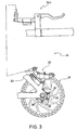
- the front disc brake assembly 12 of the present invention basically includes a disc brake caliper 30 fixedly coupled to the front fork 18, a disc brake rotor 32 fixedly coupled to the front wheel 22 and a front brake actuator 34a.
- the rear disc brake assembly 14 is identical to the front disc brake assembly 12, except the rear disc brake assembly includes a modified rear brake actuator 34b.
- the rear brake actuator 34b is identical to the front brake actuator 34a, except the rear brake actuator 34b is a mirror image of the front brake actuator 34a.
- the rear disc brake assembly 14 of the present invention basically includes a disc brake caliper 30 fixedly coupled to the rear fork 20, a disc brake rotor 32 fixedly coupled to the rear wheel 24 and the rear brake actuator 34b.
- the front and rear disc brake assemblies 12 and 14 are conventional, except for the connection of the disc brake rotors 32 to the front and rear wheels 22 and 24, respectively. Thus, the front and rear disc brake assemblies 12 and 14 will not be discussed and/or illustrated in detail herein, except for the connection of the disc brake rotors 32 to the front and rear wheels 22 and 24.
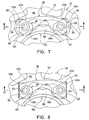
- each of the disc brake rotors 32 is fixedly coupled to one of the front and rear wheels 22 and 24 via a plurality of fasteners 36 and a plurality of locking members 38 to form a bicycle component assembly in accordance with the present invention.
- the front and rear wheels 22 and 24, the disc brake rotors 32 and the fasteners 36 will be discussed in more detail below.
- the locking members 38 are mounted between the disc brake rotors 32 and portions of the fasteners 36 to securely fasten the disc brake rotors 32 to the front and rear wheels 22 and 24.
- the locking members 38 are designed to frictionally engage the disc brake rotors 32 and to prevent relative rotation of the locking members 38 and relative rotation of the fasteners 36, as discussed below in more detail.
- each locking member 38 is preferably a substantially flat thin metal plate manufactured by stamping or any other suitable manufacturing technique.
- each locking member 38 is preferably constructed of iron alloy such as stainless steel type 304 (SUS 304).
- Each locking member 38 basically includes a first attachment portion 42a, a second attachment portion 42b and a connecting portion 44 extending between the first and second attachment portions 42a and 42b.
- Each locking member 38 preferably has a substantially uniform thickness T of about 0.25 millimeters. In any event, each locking member 38 preferably has a thickness T of less than about 0.5 millimeters as seen in Figure 14.
- each locking member 38 is preferably integrally formed as a one-piece unitary member by stamping or any other suitable manufacturing technique.
- the first attachment portion 42a, the second attachment portion 42b and the connecting portion 44 are preferably integrally formed together as a one-piece, unitary sheet metal member.
- the first attachment portion 42a is preferably an annular member that includes a first contact surface 46a, a first engagement surface 48a, a first hole 50a and a first end flange section 52a.
- the first contact surface 46a and the first engagement surface 48a are preferably substantially parallel surfaces.
- the hole 50a extends between the first contact surface 46a and the first engagement surface 48a.
- the first contact surface 46a and the first engagement surface 48a are substantially parallel annular surfaces with the first hole 50a extending therebetween.
- the first end flange section 52a is preferably an arcuate-shaped tab that extends upwardly and outwardly from the first contact surface 46a and the first engagement surface 48a.
- first flange section 52a is preferably angled relative to the first contact surface 46a and the first engagement surface 48a.
- first end flange 52a is preferably angled about thirty degrees relative to the first contact surface 46a and the first engagement surface 48a.
- the first end flange section 52a is designed to be bent (e.g., plastically deformed) to prevent rotation of one of the fasteners 36, as discussed below in more detail.
- the first contact surface 46a is preferably a smooth untreated annular surface, while the first engagement surface 48a is preferably a frictionally treated surface that has a higher coefficient of friction than the first contact surface 46a.
- the first engagement surface 48a is arranged to contact the disc brake rotor 32 to prevent translational/rotational movement of the first attachment portion 42a.
- the first engagement surface 48a is a preferably a textured surface that is preferably formed during the stamping of each locking member 38.
- the term "frictionally treated surface” as used herein should be construed to mean any surface that is modified in any way to improve/increase frictional characteristics of the surface. Of course, the present invention should not be limited to the specific embodiments of frictionally treated surfaces illustrated herein.
- textured surface should be construed to mean a non-smooth surface including, but not limited to, any rough, uneven, course, bumpy, irregular or jagged surface with improved/increased frictional characteristics.
- present invention should not be limited to the specific embodiments of textured surfaces illustrated herein.
- the first frictionally treated engagement surface 48a preferably includes a plurality of parallel first grooves 49a extending in a transverse direction.
- the first grooves 49a are preferably substantially perpendicular to the connecting portion 44, as discussed below in more detail.
- the first grooves 49a preferably have a depth D of about 0.1 millimeters and a width W of about 0.4 millimeters as shown in Figure 14.
- the first grooves 49a are preferably spaced a distance L of about 1.0 millimeter from each other.
- Each of the first grooves 49a also preferably has a substantially curved V-shaped cross-section as shown in Figure 14.
- first grooves 49a can be formed using any suitable manufacturing technique as needed and/or desired.
- first engagement surface 48a can be formed with additional grooves or can have other configurations of first grooves, as discussed below with reference to other preferred embodiments of the present invention.
- first engagement surface 48a can be an alternate textured surface (e.g. a textured surface formed without grooves) and/or can be coated with friction material, as discussed below with reference to other preferred embodiments of the present invention.
- first grooves 49a can have different cross-sectional shapes as needed and/or desired.
- the second attachment portion 42b is a mirror image of the first attachment portion 42a.
- the second attachment portion 42b is preferably an annular member that includes a second contact surface 46b, a second engagement surface 48b, a second hole 50b and a second end flange section 52b.
- the second contact surface 46b and the second engagement surface 48b are preferably substantially parallel surfaces.
- the hole 50b extends between the second contact surface 46b and the second engagement surface 48b.
- the second contact surface 46b and the second engagement surface 48b are substantially parallel annular surfaces with the second hole 50b extending therebetween.
- the second end flange section 52b is preferably an arcuate-shaped tab that extends upwardly and outwardly from the second contact surface 46b and the second engagement surface 48b.
- the second flange section 52b is preferably angled relative to the second contact surface 46b and the second engagement surface 48b.
- the second flange section 52b is preferably angled about thirty degrees relative to the second contact surface 46b and the second engagement surface 48b.
- the second end flange section 52b is designed to be bent (e.g., plastically deformed) to prevent rotation of one of the fasteners 36, as discussed below in more detail.
- the second contact surface 46b is preferably a smooth untreated annular surface, while the second engagement surface 48b is preferably a frictionally treated surface that has a higher coefficient of friction than the second contact surface 46b.
- the second engagement surface 48b is arranged to contact the disc brake rotor 32 to prevent translational/rotational movement of the second attachment portion 42b.
- the second engagement surface 48b is a preferably a textured surface that is preferably formed during the stamping of each locking member 38.
- the second engagement surface 48b preferably includes a plurality of parallel second grooves 49b extending in a transverse direction. In other words, the second grooves 49b are preferably substantially perpendicular to the connecting portion 44, as discussed below in more detail.
- the second grooves 49b are preferably parallel to the first grooves 49a of the first attachment portion 42a.
- the second grooves 49b are identical to the first grooves 49a, and thus, also preferably have a depth D of about 0.1 millimeters and a width W of about 0.4 millimeters (shown only in Figure 14 with reference to the first attachment portion 42a).
- the second grooves 49b are preferably spaced a distance L of about 1.0 millimeter from each other.
- Each of the second grooves 49b also preferably has a substantially curved V-shaped cross-section.
- the second attachment portion 42b is preferably identical to the first attachment portion 42a except the second attachment portion 42b is a mirror image of the first attachment portion 42a.
- the second grooves 49b can be formed using any suitable manufacturing technique as needed and/or desired.
- the second engagement surface 48b can be formed with additional grooves or can have other configurations of second grooves as discussed below with reference to other preferred embodiments of the present invention.
- the second engagement surface 48b also can be different from the first engagement surface 48a, if needed and/or desired. However, preferably the second engagement surface 48b is identical to the first engagement surface 48a.
- the second engagement surface 48b can be an alternate textured surface (e.g.
- a textured surface formed without grooves can be coated with friction material, as discussed below with reference to other preferred embodiments of the present invention.
- the second grooves 49b can have different cross-sectional shapes as needed and/or desired.
- the connecting portion 44 is a curved member that extends between the first attachment portion 42a and the second attachment portion 42b as best seen in Figures 11-14.
- the connecting portion 44 extends from one side of the first attachment portion 42a in a direction substantially opposite to the direction of the first end flange section 52a.
- the connecting portion 44 also extends from one side of the second attachment portion 42b in a direction substantially opposite to the direction of the second end flange section 52b.
- the first and second end flange sections 52a and 52b form first and second transverse free edges of each locking member 38.
- the connecting portion 44 also preferably has a thickness T of about 0.25 millimeters (shown only in Figure 14 with reference to the first attachment portion 42a). In any event, the connecting portion 44 preferably has a thickness T of less than about 0.5 millimeters.
- the connecting portion 44 has a third engagement surface 45 that extends between the first and second engagement surfaces 48a and 48b.
- the third engagement surface 45 is substantially coplanar with the first and second engagement surfaces 48a and 48b.
- the third engagement surface 45 is arranged to contact the disc brake rotor 32.
- the third engagement surface 45 is a smooth untreated surface.
- the third engagement surface 45 preferably has a coefficient of friction substantially equal to the coefficient of friction of the first and second contact surfaces 46a and 46b.
- the third engagement surface 45 can be a frictionally treated surface with a higher coefficient of friction than the first and second contact surfaces 46a and 46b.
- the third engagement surface 45 can be a textured surface and/or can be coated with a friction material, as discussed below with reference to other preferred embodiments of the present invention.
- the third engagement surface 45 can have a configuration identical to the first and second engagement surfaces 48a and 48b if needed and/or desired
- the front and rear wheels 22 and 24 are conventional, except for the attachment of the disc brake rotors 32 thereto. Thus, the front and rear wheels 22 and 24 will not be discussed and/or illustrated in detail herein, except as related to the attachment of the disc brake rotors 32 thereto via the fasteners 36 and the locking members 38. Additionally, the rear wheel 24 is identical to the front wheel 22, except that the rear wheel 24 includes a conventional freewheel coupled thereto in a convention manner. Thus, the rear wheel 24 will not be discussed and/or illustrated in detail herein. Rather, it will be apparent to those skilled in the art from this disclosure that most of the descriptions and illustrations of the front wheel 22 also apply to the rear wheel 24.
- the front wheel 22 basically includes a rim coupled to a front hub 62 via a plurality of spokes in a conventional manner as seen in Figure 1.
- any suitable rim could be coupled to the front hub 62 utilizing any suitable technique such as those that are well known in the art, without departing from the scope of the present invention.
- the front hub 62 is a disc brake hub that basically includes a hub body 64 and a hub axle 66 as best seen in Figures 4-6.
- the hub axle 66 is rotatably mounted within an interior passageway of the hub body 64 in a conventional manner such that the hub body 64 freely rotates about the hub axle 66.
- the hub body 64 includes a rotor attachment portion or mounting member 68 arranged at one end thereof as best seen in Figure 6.
- the rotor attachment portion 68 is preferably integrally formed with the hub body 64 to form the bicycle mounting member with the hub body 64.
- the rotor attachment portion 68 could be a separate member from the hub body 64 that is fixedly coupled to the hub body 64.
- the rotor attachment portion 68 preferably includes a plurality (six) of threaded attachment openings 70 formed therein.
- the threaded openings 70 are blind threaded bores configured to threadedly couple the fasteners 36 therein to fixedly couple the disc brake rotor 32 thereto.
- the attachment openings 70 could be unthreaded through openings such that nuts can be used with the fasteners 36 if needed and/or desired.
- the threaded openings 70 can be considered first or second threaded attachment openings depending on the arrangement of the locking members 38, as discussed below in more detail.
- the three threaded openings 70 aligned with the first holes 50a of the locking members 38 are considered first attachment openings, while the three threaded openings 70 aligned with the second holes 50b of the locking members 38 are considered second attachment openings.
- the rotor attachment portion 68 has a non-circular shape with a flat free end surface designed to contact the inner periphery of the rotor 32.
- the rotor attachment portion 68 could have other configurations as needed and/or desired without departing from the scope of the present invention.
- the disc brake rotor 32 is conventional. Thus, the disc brake rotor 32 will not be discussed and/or illustrated in detail herein, except as related to the connection of the disc brake rotor 32 to the rotor attachment portion 68.
- the disc brake rotor 32 basically includes an attachment portion 80 and a braking portion 82.
- the attachment portion 80 forms the inner periphery of the disc brake rotor 32, while the braking portion 82 forms the outer periphery of the disc brake rotor 32.
- the attachment portion 80 is preferably integrally formed with the braking portion 82 as a one-piece unitary member to form a component attachment member.
- the disc brake rotor 32 could be constructed in any suitable manner as needed and/or desired.
- the attachment portion 80 includes a plurality (six) of through openings 84 formed therein and a pair of coupling surfaces 86.
- the through openings 84 extend between the coupling surfaces 86.
- the through openings 84 are arranged to be aligned with the threaded openings 70 of the rotor attachment portion 68.
- the through openings 84 are configured to receive the fasteners 36 therethrough, as discussed below in more detail.
- the through openings 84 can be considered first or second through openings.
- the three through openings 84 aligned with the first holes 50a of the locking members 38 are considered first through openings
- the three through openings 84 aligned with the second holes 50b of the locking members 38 are considered second through openings.
- one of the coupling surfaces 86 contacts the rotor attachment portion 68 while the other coupling surface 86 contacts the first and second engagement surfaces 48a and 48b of the locking members 38, as discussed below in more detail.
- the disc brake rotor 32 is coupled to the rotor attachment portion 68 of the hub body 64 via a plurality (6) of the fasteners 36.
- the fasteners 36 are preferably identical to each other.
- each of the fasteners includes a head portion 90 and a threaded shaft portion 92 extending from the head portion 90.
- each shaft portion 92 is threadedly coupled within one of the blind threaded openings 70 of the rotor attachment portion 68.
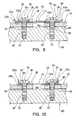
- each shaft portion 92 preferably extends through one of the first and second holes 50a and 50b of the locking members 38, and through one of the through openings 84 of the disc brake rotor 32.
- Each of the head portions 90 preferably has a non-circular outer shape in order to selectively engage one of the end flange sections 52a or 52b of one of the locking members 38. Additionally, a blind hexagonal bore 94 is preferably formed in each of the head portions 92 to facilitate use of a hexagonal wrench (not shown) to rotate the fasteners 36.
- the non-circular outer shape of the head portion 90 is preferably a substantially triangular shape formed by three flat surfaces 96. One or more of the flat surfaces 96 of each fastener 36 will engage one of the end flange sections 52a or 52b of one of the locking members 38 to prevent relative rotation of the fasteners 36, as discussed below.
- the fasteners 36 and the locking members 38 are used to securely fasten the disc brake rotor 32 to the rotor attachment portion 68 of the hub body 64.
- the disc brake rotor 32 is arranged adjacent to the rotor attachment portion 68 such that the through openings 84 are aligned with the threaded openings 70.
- the locking members 38 are then arranged adjacent one of the coupling surfaces 86 of the disc brake rotor 32 (e.g. the coupling surface 86 facing away from the rotor attachment portion 68).
- the first and second engagement surfaces 48a and 48b of each of the (three) locking members are arranged to contact the coupling surface 86 of the disc brake rotor 32 that faces away from the rotor attachment portion 68.
- the locking members 38 are further arranged so that the first and second holes 50a and 50b of each locking member 38 are aligned with a pair of the through openings 84 of the disc brake rotor 32.
- the shaft portions 92 of the (six) fasteners 36 are then inserted through the first and second openings 50a and 50b of the locking members 38.
- the shaft portions 92 are further inserted through the through openings 84 of the disc brake rotor 32 and into the threaded attachment openings 70 of the rotor attachment portion 68.
- the head portions 90 of the fasteners 36 can be first rotated by hand such that the threaded shaft portions 92 engage the threaded attachment openings 70 of the rotor attachment portion 68.
- a conventional hexagonal wrench (not shown) is utilized to tighten the fasteners 36.
- the fasteners 36 could be rotated in any conventional manner if needed and/or desired.
- the head portions 90 press against the contact surfaces 46a and 46b of the respective locking members 38.
- the first and second engagement surfaces 48a and 48b of the respective locking members 38 are pressed tightly against the disc brake rotor 32.
- the first and second engagement surfaces 48a and 48b of the locking members frictionally engage the disc brake rotor 32 to prevent relative translational/rotational movement between the locking members 38 and the disc brake rotor 32. Because the fasteners 36 are identical to each other, tightening of the fasteners 36 naturally applies opposing forces on the locking members 38. However, due to the frictional engagement between the first and second attachment portions 42a and 42b and the disc brake rotor 32, stresses on the connecting portions 44 of the locking members 38 are reduced.
- first and second end flange sections 52a and 52b of the respective locking members are bent using a flat-head screwdriver or a similar tool.
- first and second end flange sections 52a and 52b are bent to form a right angle (e.g., 90 degrees) with the first and second contact surfaces 46a and 46b. More specifically, the first and second end flange sections 52a and 52b are preferably bent such that they contact at least one of the flat surfaces 96 of the respective head portions 90. Of course, the first and second end flange sections 52a and 52b can be bent such that they contact a pair of the flat surfaces 96 of the respective head portions 90 depending on the orientation of the head portions 90. Thus, the end flange sections 52a and 52b engage the head portions 90 of the fasteners 36 to prevent relative rotation thereof. Thus, a tight permanent connection between the disc brake rotor 32 and the rotor attachment portion 68 is attained via the fasteners 36 and the locking members 38, without damage to the locking members 38.
- a right angle e.g. 90 degrees
- the end flange sections 52a and 52b In order to remove the disc brake rotor 32 from the rotor attachment portion 68 such as for service, the end flange sections 52a and 52b must first be bent out of engagement with the one or more flat surfaces 96 of the head portions 90. Then, the fasteners 36 can be rotated to release the disc brake rotor 32 from the rotor attachment portion 68.
- a locking member 238 is illustrated in accordance with a second embodiment of the present invention.
- the locking member 238 is designed to be used with the disc brake rotor 32, the rotor attachment portion 68 and the fasteners 36 of the first embodiment.
- a plurality (three) of identical locking members 238 are used with the disc brake rotor 32, the rotor attachment portion 68 and the fasteners 36 of the first embodiment.
- only one locking member 238 will be discussed and illustrated herein.
- the locking member 38 is used in a manner identical to the first embodiment.
- the locking member 238 of this second embodiment is identical to the locking member 38 of the first embodiment, except that the locking member 238 includes modified first and second frictionally treated engagement surfaces 248a and 248b, respectively.
- the first and second engagement surfaces 248a and 248b are modified versions of the first and second engagement surfaces 48a and 48b of the first embodiment.
- the locking member 238 will not be discussed and/or illustrated in detail herein. Rather, the following description will focus mainly on the differences between the locking member 238 and the locking member 38 of the first embodiment.
- the descriptions and/or illustrations of the locking member 38 of the first embodiment also apply to the locking member 238 of this second embodiment, except as explained below.
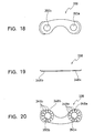
- the first engagement surface 248a preferably includes a plurality of parallel first grooves 249a
- the second engagement surface 248b preferably includes a plurality of parallel second grooves 249b.
- the first and second grooves 249a and 249b are identical to the grooves 49a and 49b of the first embodiment except that the grooves 249a and 249b are spaced further apart from each other, respectively.
- the first grooves 249a are preferably spaced about 2.0 millimeters from each other, while the second grooves 249b are also preferably spaced about 2.0 millimeters from each other.
- the grooves 249a and 249b preferably have cross-sectional shapes identical to the grooves 49a and 49b of the first embodiment.
- the first and second engagement surfaces 248a and 248b also preferably include a plurality of third and fourth grooves 251a and 251b, respectively.
- the third grooves 251a are preferably parallel grooves arranged at ninety degree angles relative to the plurality of first grooves 249a. Otherwise, the third grooves 251a are identical to the first grooves 249a.
- the fourth grooves 251b are also preferably parallel grooves arranged at ninety degree angles relative to the second grooves 249b. Otherwise, the fourth grooves 251b are identical to the second grooves 249b.
- the third grooves 251a are preferably spaced about 2.0 millimeters from each other, while the fourth grooves 251b are also preferably spaced about 2.0 millimeters from each other.
- the first and second engagement surfaces 248a and 248b are textured surfaces that have a substantially grid-type pattern.
- a locking member 338 is illustrated in accordance with a third embodiment of the present invention.
- the locking member 338 is designed to be used with the disc brake rotor 32, the rotor attachment portion 68 and the fasteners 36 of the first embodiment.
- a plurality (three) of identical locking members 338 are used with the disc brake rotor 32, the rotor attachment portion 68 and the fasteners 36 of the first embodiment.
- only one locking member 338 will be discussed and illustrated herein.
- the locking member 338 is used in a manner identical to the first embodiment.
- the locking member 338 of this third embodiment is identical to the locking member 38 of the first embodiment, except that the locking member 338 includes modified first and second frictionally treated engagement surfaces 348a and 348b, respectively.
- the first and second engagement surfaces 348a and 348b are modified versions of the first and second engagement surfaces 48a and 48b of the first embodiment.
- the locking member 338 will not be discussed and/or illustrated in detail herein. Rather, the following description will focus mainly on the differences between the locking member 338 and the locking member 38 of the first embodiment.
- the descriptions and/or illustrations of the locking member 38 of the first embodiment also apply to the locking member 338 of this third embodiment, except as explained below.
- the first engagement surface 348a preferably includes a plurality of first grooves 349a
- the second engagement surface 348b preferably includes a plurality of second grooves 349b.
- the first and second grooves 349a and 349b are identical to the grooves 49a and 49b of the first embodiment except that the grooves 349a and 349b are not parallel grooves.
- the first and second grooves 349a and 349b extend radially outwardly from first and second holes 350a and 350b, respectively.
- the first grooves 349a are preferably radially spaced about thirty degrees from each other, while the second grooves 349b are also preferably radially spaced about thirty degrees from each other.
- the first and second grooves 349a and 349b preferably have cross-sectional shapes identical to the first and second grooves 49a and 49b of the first embodiment.
- the first and second engagement surfaces 348a and 348b are textured surfaces.
- a locking member 438 is illustrated in accordance with a fourth embodiment of the present invention.
- the locking member 438 is designed to be used with the disc brake rotor 32, the rotor attachment portion 68 and the fasteners 36 of the first embodiment.
- a plurality (three) of identical locking members 438 are used with the disc brake rotor 32, the rotor attachment portion 68 and the fasteners 36 of the first embodiment.
- only one locking member 438 will be discussed and illustrated herein.
- the locking member 438 is used in a manner identical to the first embodiment.
- the locking member 438 of this fourth embodiment is identical to the locking member 38 of the first embodiment, except that the locking member 438 includes modified first and second frictionally treated engagement surfaces 448a and 448b, respectively.
- the locking member 438 also preferably includes a modified frictionally treated third engagement surface 445 in this fourth embodiment.
- the first and second engagement surfaces 448a and 448b are modified versions of the first and second engagement surfaces 48a and 48b of the first embodiment.
- first and second engagement surfaces 448a and 448b are preferably textured surfaces that do not include the grooves 49a and 49b of the first embodiment, respectively. Rather, the first and second engagement surfaces 448a and 448b are preferably textured by shot or sand blasting.
- the third engagement surface 445 is also preferably a textured surface that is formed by shot or sand blasting.
- the first, second and third engagement surface 448a, 448b and 445 are preferably non-smooth or rough/course surfaces due to the shot blasting.
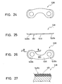
- a locking member 538 is illustrated in accordance with a fifth embodiment of the present invention.
- the locking member 538 is designed to be used with the disc brake rotor 32, the rotor attachment portion 68 and the fasteners 36 of the first embodiment.
- a plurality (three) of identical locking members 538 are used with the disc brake rotor 32, the rotor attachment portion 68 and the fasteners 36 of the first embodiment.
- only one locking member 538 will be discussed and illustrated herein.
- the locking member 538 is used in a manner identical to the first embodiment.
- the locking member 538 of this fifth embodiment is identical to the locking member 438 of the fourth embodiment, except that the locking member 538 includes modified first and second frictionally treated engagement surfaces 548a and 548b, respectively.
- the locking member 538 also preferably includes a modified frictionally treated third engagement surface 545 in this fifth embodiment.
- the first and second engagement surfaces 548a and 548b are modified versions of the first and second engagement surfaces 448a and 448b of the fourth embodiment.
- the locking member 538 will not be discussed and/or illustrated in detail herein. Rather, the following description will focus mainly on the differences between the locking member 538 and the locking member 438 of the fourth embodiment.
- the descriptions and/or illustrations of the locking member 38 of the first embodiment and the locking member 438 of the fourth embodiment also apply to the locking member 538 of this fifth embodiment, except as explained below.
- first and second engagement surfaces 548a and 548b are identical to the first and second engagement surfaces 448a and 448b of the fourth embodiment except a friction material coating or layer 551 is applied thereto.
- the third engagement surface 545 is also preferably identical to the third engagement surface 445 of the fourth embodiment except it also preferably has the friction material 551 applied thereto.
- the first and second engagement surfaces 548a and 548b have a configuration identical to the third engagement surface 545.
- the locking member 538 is formed of a base layer of a one-piece, unitary sheet metal material (e.g. identical to the locking member 438) with the friction material 551 at least partially coating one side.
- the friction material 551 is a rubber material such as hydrogenated nitrile rubber (NBR) that overlies the textured surfaces of the locking member 538.
- NBR hydrogenated nitrile rubber
- the friction material coating 551 has a thickness of about 0.1 millimeters.
- the locking member 538 will have an overall thickness of about 0.35 millimeters (where the friction material is applied thereto).
- the metal layer of the locking member 538 e.g. locking member 438 of the fourth embodiment
- the metal layer can be 0.25 millimeters thick, or thinner (e.g. about 0.15 millimeters thick).
Landscapes
- Engineering & Computer Science (AREA)
- Mechanical Engineering (AREA)
- General Engineering & Computer Science (AREA)
- Physics & Mathematics (AREA)
- Fluid Mechanics (AREA)
- Braking Arrangements (AREA)
- Fittings On The Vehicle Exterior For Carrying Loads, And Devices For Holding Or Mounting Articles (AREA)
Applications Claiming Priority (2)
| Application Number | Priority Date | Filing Date | Title |
|---|---|---|---|
| US153863 | 1988-02-09 | ||
| US10/153,863 US6974275B2 (en) | 2002-05-24 | 2002-05-24 | Locking member for bicycle component |
Publications (3)
| Publication Number | Publication Date |
|---|---|
| EP1364868A2 true EP1364868A2 (de) | 2003-11-26 |
| EP1364868A3 EP1364868A3 (de) | 2004-03-24 |
| EP1364868B1 EP1364868B1 (de) | 2005-09-28 |
Family
ID=29400543
Family Applications (1)
| Application Number | Title | Priority Date | Filing Date |
|---|---|---|---|
| EP03011445A Expired - Lifetime EP1364868B1 (de) | 2002-05-24 | 2003-05-20 | Verriegelungselement für Fahrradkomponenten |
Country Status (6)
| Country | Link |
|---|---|
| US (1) | US6974275B2 (de) |
| EP (1) | EP1364868B1 (de) |
| JP (1) | JP2003343617A (de) |
| CN (1) | CN1319805C (de) |
| DE (1) | DE60301693T2 (de) |
| TW (1) | TWI224065B (de) |
Families Citing this family (12)
| Publication number | Priority date | Publication date | Assignee | Title |
|---|---|---|---|---|
| FR2856755B1 (fr) * | 2003-06-26 | 2007-03-23 | Snecma Moteurs | Dispositif de fixation par vis et ecrous |
| DE102006058140B4 (de) * | 2006-03-22 | 2009-06-10 | Airbus Deutschland Gmbh | Bolzenverbindung |
| WO2008037271A1 (en) * | 2006-09-26 | 2008-04-03 | Fluid Automation Systems S.A. | Valve unit and methods for fastening a valve unit to a base |
| US8297416B2 (en) * | 2008-11-07 | 2012-10-30 | Kitchell Edward W | Rotor device and method of making same |
| US9447812B2 (en) | 2011-06-01 | 2016-09-20 | Shimano, Inc. | Apparatus to assist mounting a bicycle component |
| US8733518B1 (en) * | 2012-11-30 | 2014-05-27 | Cwd, Llc | Drive pin assembly |
| US9821366B2 (en) | 2014-06-01 | 2017-11-21 | Shimano Inc. | Disc brake rotor and method of manufacturing disc brake rotor |
| US9266576B1 (en) | 2015-04-23 | 2016-02-23 | Arthur J. dela Houssaye | Tamper evident wheel support |
| CN109424672A (zh) * | 2017-09-01 | 2019-03-05 | 天心工业股份有限公司 | 自行车刹车碟盘 |
| JP2019065873A (ja) * | 2017-09-28 | 2019-04-25 | 株式会社アドヴィックス | 車両ブレーキおよび摩擦係合部材の周面の加工方法 |
| JP2019203585A (ja) * | 2018-05-25 | 2019-11-28 | 株式会社NejiLaw | ねじ締結機構の逆回転防止構造及びねじ締結機構の介在部材 |
| US12377790B2 (en) * | 2022-05-25 | 2025-08-05 | Ford Global Technologies, Llc | Sensor assembly and method of installing to a vehicle |
Family Cites Families (28)
| Publication number | Priority date | Publication date | Assignee | Title |
|---|---|---|---|---|
| US561604A (en) * | 1896-06-09 | Island | ||
| US382789A (en) * | 1888-05-15 | benton | ||
| US2128429A (en) * | 1935-03-25 | 1938-08-30 | Illinois Tool Works | Locking device |
| US2423918A (en) | 1944-11-27 | 1947-07-15 | Palnut Company | Nut or bolt lock |
| US2879092A (en) * | 1957-12-13 | 1959-03-24 | Gen Electric | Friction shaft-coupling assembly |
| US2955690A (en) | 1958-01-16 | 1960-10-11 | United Carr Fastener Corp | Fastening device |
| US3212387A (en) * | 1962-05-08 | 1965-10-19 | California Plasteck Inc | Plastic captive screw washer |
| JPS4033379Y1 (de) * | 1964-04-08 | 1965-11-22 | ||
| US4267870A (en) * | 1978-11-13 | 1981-05-19 | The Ferry Cap & Set Screw Co. | Screw fastener with multi-point wrenching head and locking capabilities |
| DE3042388C2 (de) * | 1980-11-10 | 1982-12-09 | Vossloh-Werke Gmbh, 5980 Werdohl | Federring |
| SE436334B (sv) * | 1981-12-14 | 1984-12-03 | Rolf Olsson | Las-eller sekerhetsanordning for bultforband |
| USD276309S (en) | 1982-02-12 | 1984-11-13 | Frieberg Bengt O | Lock washer assembly |
| JPH0210831Y2 (de) * | 1985-06-06 | 1990-03-16 | ||
| JPH0180813U (de) * | 1987-11-19 | 1989-05-30 | ||
| US5562378A (en) | 1995-02-07 | 1996-10-08 | Saint Switch, Inc. | Lock washer |
| US5632362A (en) * | 1995-08-15 | 1997-05-27 | Rockshox, Inc. | Bicycle disc brake |
| US5681136A (en) | 1995-09-14 | 1997-10-28 | James F. L. Blair | Lock washer |
| JPH11294437A (ja) * | 1998-04-13 | 1999-10-26 | Ishino Gasket Kogyo Kk | 内燃機関の盲プラグシールワッシャ |
| US6347915B1 (en) | 1998-08-17 | 2002-02-19 | Alfiero Balzano | Lock washer for threaded fasteners |
| US6164421A (en) * | 1998-10-14 | 2000-12-26 | Shimano Inc. | Disc brake assembly |
| US6349800B1 (en) * | 2000-02-07 | 2002-02-26 | Shimano Inc. | Bicycle disc brake assembly |
| US6527089B2 (en) * | 2000-04-06 | 2003-03-04 | Avid, L.L.C. | Caliper drive for a bicycle ball bearing mechanical disc brake caliper |
| USH1981H1 (en) * | 2000-05-18 | 2001-08-07 | The United States Of America As Represented By The United States Department Of Energy | Bearing stress-free locking device |
| US6401882B1 (en) * | 2000-06-30 | 2002-06-11 | Shimano Inc. | Heat insulator for disc brake |
| DE10034748B4 (de) * | 2000-07-18 | 2005-01-27 | Kamax-Werke Rudolf Kellermann Gmbh & Co. Kg | Lösbares Verbindungselement für ein Fahrzeugrad, mit einem Schraubteil und einem Stützring |
| JP2002122123A (ja) * | 2000-10-13 | 2002-04-26 | Kai Kenchiku Sekkei Jimusho:Kk | 座 金 |
| JP2002122121A (ja) * | 2000-10-16 | 2002-04-26 | Shimizu Gokin Seisakusho:Kk | ネジ破損防止用の座金 |
| US6450746B1 (en) * | 2001-02-13 | 2002-09-17 | Shimano, Inc. | Screw retention device having serrations |
-
2002
- 2002-05-24 US US10/153,863 patent/US6974275B2/en not_active Expired - Fee Related
-
2003
- 2003-04-02 TW TW092107545A patent/TWI224065B/zh not_active IP Right Cessation
- 2003-05-12 JP JP2003133466A patent/JP2003343617A/ja active Pending
- 2003-05-20 DE DE60301693T patent/DE60301693T2/de not_active Expired - Lifetime
- 2003-05-20 EP EP03011445A patent/EP1364868B1/de not_active Expired - Lifetime
- 2003-05-26 CN CNB031409385A patent/CN1319805C/zh not_active Expired - Fee Related
Non-Patent Citations (1)
| Title |
|---|
| None |
Also Published As
| Publication number | Publication date |
|---|---|
| TWI224065B (en) | 2004-11-21 |
| JP2003343617A (ja) | 2003-12-03 |
| EP1364868B1 (de) | 2005-09-28 |
| US6974275B2 (en) | 2005-12-13 |
| DE60301693D1 (de) | 2006-02-09 |
| EP1364868A3 (de) | 2004-03-24 |
| DE60301693T2 (de) | 2006-03-16 |
| CN1460624A (zh) | 2003-12-10 |
| CN1319805C (zh) | 2007-06-06 |
| US20030219303A1 (en) | 2003-11-27 |
| TW200306928A (en) | 2003-12-01 |
Similar Documents
| Publication | Publication Date | Title |
|---|---|---|
| US8522931B2 (en) | Disk brake rotor | |
| EP1364868B1 (de) | Verriegelungselement für Fahrradkomponenten | |
| US7143872B2 (en) | Apparatus for retaining a bicycle disk brake rotor to a bicycle wheel hub | |
| US7628416B2 (en) | Bicycle wheel securing structure | |
| US7665584B2 (en) | Disc rotor retaining assembly | |
| US20080284127A1 (en) | Bicycle wheel securing structure | |
| USRE42635E1 (en) | Cable disc brake | |
| US7055655B2 (en) | Disc brake caliper assembly with shims | |
| US6672419B2 (en) | Motorcycle front brake rotor mounting | |
| JP3314044B2 (ja) | スポーク・リムアセンブリ、自転車リム及び自転車スポーク | |
| US6079611A (en) | Method of manufacturing ventilated brake disc | |
| EP1375331A1 (de) | Vorrichtung zum Montieren einer Bremstrommel an einen Fahrradrahmen | |
| US6126242A (en) | Bicycle wheel rim with integrally formed braking plate | |
| JP2004011889A (ja) | 自転車用ハブブレーキ装置 | |
| TWI249491B (en) | Bicycle hub with an attached cooling disk | |
| TW200307622A (en) | Actuating assembly for a bicycle control device | |
| JP2001071702A (ja) | 車両用ホイール構造 | |
| JP2004353723A (ja) | 車両用ディスクブレーキのキャリパボディ取付け構造 | |
| JP7424881B2 (ja) | ブレーキディスク及びその締結方法 | |
| JPS5939112Y2 (ja) | 車輛用ホイ−ルにおけるブレ−キデイスクの取付構造 | |
| US5620062A (en) | Bicycle brake shoe assembly | |
| JPH09222140A (ja) | ブレーキ部材の脱着構造 |
Legal Events
| Date | Code | Title | Description |
|---|---|---|---|
| PUAI | Public reference made under article 153(3) epc to a published international application that has entered the european phase |
Free format text: ORIGINAL CODE: 0009012 |
|
| AK | Designated contracting states |
Kind code of ref document: A2 Designated state(s): AT BE BG CH CY CZ DE DK EE ES FI FR GB GR HU IE IT LI LU MC NL PT RO SE SI SK TR |
|
| AX | Request for extension of the european patent |
Extension state: AL LT LV MK |
|
| PUAL | Search report despatched |
Free format text: ORIGINAL CODE: 0009013 |
|
| AK | Designated contracting states |
Kind code of ref document: A3 Designated state(s): AT BE BG CH CY CZ DE DK EE ES FI FR GB GR HU IE IT LI LU MC NL PT RO SE SI SK TR |
|
| AX | Request for extension of the european patent |
Extension state: AL LT LV MK |
|
| RIC1 | Information provided on ipc code assigned before grant |
Ipc: 7B 62L 1/00 B Ipc: 7B 62L 5/18 A Ipc: 7F 16D 65/12 B |
|
| 17P | Request for examination filed |
Effective date: 20040316 |
|
| 17Q | First examination report despatched |
Effective date: 20040528 |
|
| AKX | Designation fees paid |
Designated state(s): DE FR GB IE IT NL |
|
| GRAP | Despatch of communication of intention to grant a patent |
Free format text: ORIGINAL CODE: EPIDOSNIGR1 |
|
| GRAS | Grant fee paid |
Free format text: ORIGINAL CODE: EPIDOSNIGR3 |
|
| GRAA | (expected) grant |
Free format text: ORIGINAL CODE: 0009210 |
|
| AK | Designated contracting states |
Kind code of ref document: B1 Designated state(s): DE FR GB IE IT NL |
|
| REG | Reference to a national code |
Ref country code: GB Ref legal event code: FG4D |
|
| REG | Reference to a national code |
Ref country code: IE Ref legal event code: FG4D |
|
| REF | Corresponds to: |
Ref document number: 60301693 Country of ref document: DE Date of ref document: 20060209 Kind code of ref document: P |
|
| PG25 | Lapsed in a contracting state [announced via postgrant information from national office to epo] |
Ref country code: IE Free format text: LAPSE BECAUSE OF NON-PAYMENT OF DUE FEES Effective date: 20060522 |
|
| ET | Fr: translation filed | ||
| RAP2 | Party data changed (patent owner data changed or rights of a patent transferred) |
Owner name: SHIMANO INC. |
|
| PLBE | No opposition filed within time limit |
Free format text: ORIGINAL CODE: 0009261 |
|
| STAA | Information on the status of an ep patent application or granted ep patent |
Free format text: STATUS: NO OPPOSITION FILED WITHIN TIME LIMIT |
|
| 26N | No opposition filed |
Effective date: 20060629 |
|
| NLT2 | Nl: modifications (of names), taken from the european patent patent bulletin |
Owner name: SHIMANO INC. Effective date: 20060802 |
|
| REG | Reference to a national code |
Ref country code: IE Ref legal event code: MM4A |
|
| GBPC | Gb: european patent ceased through non-payment of renewal fee |
Effective date: 20070520 |
|
| PG25 | Lapsed in a contracting state [announced via postgrant information from national office to epo] |
Ref country code: NL Free format text: LAPSE BECAUSE OF NON-PAYMENT OF DUE FEES Effective date: 20071201 |
|
| NLV4 | Nl: lapsed or anulled due to non-payment of the annual fee |
Effective date: 20071201 |
|
| PG25 | Lapsed in a contracting state [announced via postgrant information from national office to epo] |
Ref country code: GB Free format text: LAPSE BECAUSE OF NON-PAYMENT OF DUE FEES Effective date: 20070520 |
|
| PGFP | Annual fee paid to national office [announced via postgrant information from national office to epo] |
Ref country code: FR Payment date: 20120608 Year of fee payment: 10 |
|
| REG | Reference to a national code |
Ref country code: FR Ref legal event code: ST Effective date: 20140131 |
|
| PG25 | Lapsed in a contracting state [announced via postgrant information from national office to epo] |
Ref country code: FR Free format text: LAPSE BECAUSE OF NON-PAYMENT OF DUE FEES Effective date: 20130531 |
|
| PGFP | Annual fee paid to national office [announced via postgrant information from national office to epo] |
Ref country code: IT Payment date: 20140520 Year of fee payment: 12 |
|
| PG25 | Lapsed in a contracting state [announced via postgrant information from national office to epo] |
Ref country code: IT Free format text: LAPSE BECAUSE OF NON-PAYMENT OF DUE FEES Effective date: 20150520 |
|
| PGFP | Annual fee paid to national office [announced via postgrant information from national office to epo] |
Ref country code: DE Payment date: 20170516 Year of fee payment: 15 |
|
| REG | Reference to a national code |
Ref country code: DE Ref legal event code: R119 Ref document number: 60301693 Country of ref document: DE |
|
| PG25 | Lapsed in a contracting state [announced via postgrant information from national office to epo] |
Ref country code: DE Free format text: LAPSE BECAUSE OF NON-PAYMENT OF DUE FEES Effective date: 20181201 |