EP1364907A2 - Améliorations apportées ou se rapportant à la manipulation des palettes - Google Patents
Améliorations apportées ou se rapportant à la manipulation des palettes Download PDFInfo
- Publication number
- EP1364907A2 EP1364907A2 EP03010554A EP03010554A EP1364907A2 EP 1364907 A2 EP1364907 A2 EP 1364907A2 EP 03010554 A EP03010554 A EP 03010554A EP 03010554 A EP03010554 A EP 03010554A EP 1364907 A2 EP1364907 A2 EP 1364907A2
- Authority
- EP
- European Patent Office
- Prior art keywords
- fork lift
- pallet
- spacing member
- attachment apparatus
- connection means
- Prior art date
- Legal status (The legal status is an assumption and is not a legal conclusion. Google has not performed a legal analysis and makes no representation as to the accuracy of the status listed.)
- Withdrawn
Links
Images

Classifications
-
- B—PERFORMING OPERATIONS; TRANSPORTING
- B66—HOISTING; LIFTING; HAULING
- B66F—HOISTING, LIFTING, HAULING OR PUSHING, NOT OTHERWISE PROVIDED FOR, e.g. DEVICES WHICH APPLY A LIFTING OR PUSHING FORCE DIRECTLY TO THE SURFACE OF A LOAD
- B66F9/00—Devices for lifting or lowering bulky or heavy goods for loading or unloading purposes
- B66F9/06—Devices for lifting or lowering bulky or heavy goods for loading or unloading purposes movable, with their loads, on wheels or the like, e.g. fork-lift trucks
- B66F9/075—Constructional features or details
- B66F9/12—Platforms; Forks; Other load supporting or gripping members
- B66F9/19—Additional means for facilitating unloading
Definitions
- the present invention relates to fork lift attachment apparatus, and to methods of connecting pallets to fork lifts.
- Pallets for stacking goods generally comprise a substantially planar surface constructed from parallel elongate boards, mounted on a peripheral frame comprising a number of spacers connected at the bottom by strengthening boards extending therebetween.
- the strengthening boards are generally spaced apart from the pallet surface by the spacers, such that there is an open space defined by the stacking surface, the strengthening boards and two of the spacers.
- Use of the pallets generally involve stacking desired goods onto the pallet, and manipulating the stacked pallets to a desired position by inserting the forks of a fork lift truck through the apertures defined by the spacers, strengthening boards and pallet surface, to a desired position.
- the goods stacked on the pallet may then be unloaded as desired and the fork lift truck used to reposition the pallet in the desired position for restacking.
- pallets are stacked with goods, then moved by fork lift trucks into the cargo spaces of lorries or vans.
- a fork lift attachment apparatus comprising a substantially rigid spacing member having means for connection to a fork lift, and having means for connection to a pallet, and wherein at least one of the means for connecting to a fork lift and the means for connecting to a pallet are movably mounted relative to the spacing member.
- the spacing member is a bar or rod.
- the fork lift connection means are situated at or near one end of the bar or rod and preferably the pallet attachment means are situated at or near the other end of the bar or rod.
- the spacing member is movable to increase and decrease the length of the spacing member.
- the spacing member is a telescopic elongate member.
- the means for connection to a fork lift comprises means for connection to at least one blade of the fork lift, preferably both blades of the fork lift.
- the fork lift connection means comprises a cross-bar oriented substantially perpendicular to the spacing member.
- the cross-bar is preferably oriented to provide two diametrically opposed arms extending from the spacing member.
- the cross-bar may be connected to the spacing member at one end thereof, preferably by a stem, thereby forming a T-shaped member.
- the fork lift connection means may comprise an arm, protruding from the spacing member.
- the arm may be oriented substantially perpendicular to the spacing member.
- the arm may be positioned at or near one end of the spacing member thereby forming an L-shaped at one end thereof.
- the fork lift connection means and spacing member are rotatably movable relative to one another between a first orientation in which the connection means can be operatively connected to a fork lift and a second orientation in which the connection means can be disconnected from the fork lift.
- the means for connection to a pallet comprises a cross-bar oriented substantially perpendicular to the spacing member.
- the cross-bar is preferably oriented to provide two diametrically opposed arms extending from the spacing member.
- the cross-bar may be connected to the spacing member at one end thereof, preferably by a stem, thereby forming a T-shaped member.
- the pallet connection means may comprise an arm protruding from the spacing member.
- the arm may be oriented substantially perpendicular to the spacing member.
- the arm may be located at or near one end of the spacing member thereby forming a substantially L-shape at the end thereof.
- the pallet connection means and spacing member are rotatably movable relative to one another between a first orientation in which the connection means can be operatively connected to a pallet and a second orientation in which the connection means can be disconnected from the pallet.
- both the fork lift connection means and the pallet connection means are independently movable relative to the spacing member between their respective first and second orientations.
- the fork lift attachment apparatus is constructed from metal (including alloy), such as iron, aluminium, stainless steel and the like, for example.
- the fork lift connection means comprises a cross-bar or arm, rotatably mounted to the spacing member and rotatable such that the arm in the first orientation the cross-bar or arm can be inserted behind the forks or a fork lift, and in the second orientation is oriented such that the arm or at least one of the arms of the cross-bar, are retained behind at least one of the forks of the fork lift.
- the pallet connection means comprises a cross-bar or arm, rotatably mounted to the spacing member and rotatable such that in the first orientation the cross-bar or arm can be inserted through an aperture in the structure of the pallet and a second orientation in which the arm, or at least one of the arms of the cross-bar, is retained behind a structural element of the pallet.
- the fork lift connection means and the pallet connection means both comprise cross-bars or an arm, fixedly connected to the spacing member, and connected such that the arm, or arms of the respective cross-bars, are oriented substantially perpendicular to one another, the apparatus being rotatable about the axis of the spacing member to effect movement of the connection means between the first and second orientations.
- the or each cross-bar may have only one arm, arranged to be retained behind a structural element of a pallet and/or fork lift, in the second orientation.
- a fork lift to a pallet comprising the steps of:
- the fork lift connection means is connected to one or both of the forks of the fork lift.
- the method comprises connecting the fork lift to a pallet which is unreachable by the forks of the fork lift, and the method further comprises after step (b), moving the fork lift to effect movement of the pallet to a position wherein the forks of the fork lift can connect to the pallet, after disconnection of the fork lift attachment apparatus.
- the fork lift attachment apparatus is as described for the first aspect of the invention.
- a third aspect of the invention there is provided a method of connecting a fork lift to a pallet of the second aspect of the invention, using a fork lift attachment apparatus of the first aspect of the invention.
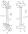
- FIGS 1 and 2 illustrate a preferred embodiment of a fork lift attachment apparatus 2 of the invention.
- the attachment apparatus 2 comprises a spacing member in the form of a rigid bar 4.
- the rigid bar 4 has at one end thereof a fork lift connection means in the form of a T-bar 6, which comprises a cross-bar 10, perpendicular to the rigid bar 4, and a stem 12 connected to the rigid bar 4.
- a pallet connection means in the form of a T-bar 8 which comprises a cross-bar 14 and stem 16, the cross-bar 14 being perpendicular to the rigid bar 4 of the attachment apparatus 2.
- Both of the T-bars 6 and 8 are rotatably connected to the respective ends of the rigid bar 4, such that they may be rotated round the longitudinal axis of the rigid bar 4.
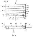
- a pallet 18 generally comprises spaced apart and parallel top surface beams 20, which are connected at either end thereof by cross beams 24 perpendicular to the top surface beams 20. Extending from the cross beams 24 are corner spacers 22, attached to the bottom of which are spaced apart bottom surface beams 26. Thus, the top surface beams 20 are separated from the bottom surface beams 26 by a cavity 27.
- the pallet 18 is loaded with desired goods, and for example, transported on the back of a lorry or van.
- the attachment apparatus 2 is oriented towards the pallet 18 and the T-bar 8 rotated such that the cross-bar 14 fits between the top surface beams 20 and bottom surface beams 26 of the pallet 18.
- the cross-bar 14 is inserted between the top 20 and bottom 26 surface beams, into the cavity 27 of the pallet 18.
- the T-bar 8 is then rotated such that the cross-bar 14 extends through the gap 23 between parallel and spaced apart top surface beams 20, and through the gap 23 located between parallel and spaced apart bottom surface beams 26.
- One of the arms of the cross-bar 14 thus protrudes above the plane of the top surface beams 20 and the end of the other of the arms of the cross-bar 14 abuts the floor of the lorry or van, parallel with the bottom surface beam 26.
- the arms of the cross-bar 14 abut the side surface of one of the top 20 and bottom 26 surface beams, therefore pulling the pallet out of the van or lorry at the same time.
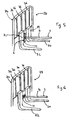
- Figures 5 and 6 illustrate the fork lift blades of a fork lift which comprises left and right fork lift blades 30 and 32, which include substantially upright portions 29 and 31 respectively.
- the upright portions 29 and 31 are connected to a fork support frame 34 which include a plurality of substantially upright support bars 36.
- the cross-bar 10 of the T-bar 6 is rotated about the rigid bar 4, such that the arms of the cross-bar 10 are parallel with the substantially vertical portions 29 and 31 of the forks 30 and 32 of the fork lift 28, and are positioned in the gap between the forks 30 and 32.
- the fork lift 28 is then moved forward such that the cross-bar 10 extends between the forks 30 and 32, behind the forks.
- the cross-bar 10 is then rotated about the rigid bar 4 such that the arms of the cross-bar 10 extend perpendicular to the substantially vertical portions 29 and 30 of the fork lift 28, behind the forks 30 and 32, as shown in Figure 6.
- the fork lift 28 is reversed, such that the arms of the cross-bar T abut the substantially vertical portions 29 and 31 of the forks 30 and 32. Further reverse movements of the fork lift 28 results in movement of the pallet 18 from the back of the truck or lorry, until the pallet 18 is at the opening to the cargo bay of the truck or lorry.
- the attachment apparatus 2 is then disconnected from both the pallet and the fork lift by rotating the T-bars 6 and 8 to their respective first orientations as described above.
- the attachment apparatus 2 is then removed, and the forks of the fork lift 28 manoeuvred such that they extend into the cavity 27 between the top 20 and bottom 26 surface beams of the pallet 18.
- the pallet 18 may then be completely removed from the back of the truck or lorry by the fork lift 28.
- the T-bar 8 of the pallet connection means may be oriented at different positions with respect to the pallet 18, such that only one of the arms of the cross-bar 14 may connect to the pallet 18, such as extending into the gap 23 between parallel top surface beams 20 from above the top surface beams 20.
- the fork lift connection T-bar 6 may also be inserted in the spaces between the support bars 36 of the fork lift fork back support 34. Furthermore, the fork lift connection T-bar 6 may be oriented such that only one of the arms of the cross-bar 10 connects to a fork 30 or 32, or a support bar 36 of the fork lift back support 34.
- the rigid bar 4 of the attachment apparatus 2 may also be extendable and retractable, such as by utilising a telescopic bar 4 such that the distance between the T-bar 6 and 8 may be extended and shortened depending on the access distance of a pallet 18 to be removed from, for example, the back of a truck or lorry.
- Figure 7 illustrates a second preferred embodiment of a fork lift attachment apparatus 2 of the invention.
- the fork lift attachment apparatus 2 of Figure 7 is similar to that of Figures 1 and 2 and like numerals represent like components.
- the fork lift connection means 6 comprises a single member having a single protruding arm 40, extending perpendicular to the rigid bar 4.
- the pallet connection means 8 comprises a single member having a single protruding arm 42, extending perpendicular from the rigid bar 4. Both the fork lift connection means 6 and the pallet connection means 8 are rotatable about the rigid bar 4, such that they may be rotated around the longitudinal axis of the rigid bar 4.
- the apparatus 2 of Figure 7 is substantially the same as use of the apparatus 2 of the embodiments shown in Figures 1 and 2, except that the single members 40 and 42 are arranged to be connected to a fork lift and pallet respectively behind a single structural element of each of the fork lift and pallets.
- the rigid bar 4 may be telescopic
- the fork lift connection means 6 and pallet connection means 8 may be rigidly connected to the rigid bar 4, but oriented such that the protruding arms 40 and 42 extend diametrically opposed on the rigid bar 4.
Landscapes
- Engineering & Computer Science (AREA)
- Transportation (AREA)
- Structural Engineering (AREA)
- Civil Engineering (AREA)
- Life Sciences & Earth Sciences (AREA)
- Geology (AREA)
- Mechanical Engineering (AREA)
- Forklifts And Lifting Vehicles (AREA)
Applications Claiming Priority (2)
| Application Number | Priority Date | Filing Date | Title |
|---|---|---|---|
| GBGB0211681.2A GB0211681D0 (en) | 2002-05-22 | 2002-05-22 | Improvements in and relating to pallet handling |
| GB0211681 | 2002-05-22 |
Publications (2)
| Publication Number | Publication Date |
|---|---|
| EP1364907A2 true EP1364907A2 (fr) | 2003-11-26 |
| EP1364907A3 EP1364907A3 (fr) | 2005-06-08 |
Family
ID=9937111
Family Applications (1)
| Application Number | Title | Priority Date | Filing Date |
|---|---|---|---|
| EP03010554A Withdrawn EP1364907A3 (fr) | 2002-05-22 | 2003-05-12 | Améliorations apportées ou se rapportant à la manipulation des palettes |
Country Status (2)
| Country | Link |
|---|---|
| EP (1) | EP1364907A3 (fr) |
| GB (1) | GB0211681D0 (fr) |
Cited By (1)
| Publication number | Priority date | Publication date | Assignee | Title |
|---|---|---|---|---|
| CN116946602A (zh) * | 2023-08-31 | 2023-10-27 | 江苏海事职业技术学院 | 一种仓储物流用堆垛设备及其方法 |
Family Cites Families (5)
| Publication number | Priority date | Publication date | Assignee | Title |
|---|---|---|---|---|
| US62309A (en) * | 1867-02-26 | Improvement in saw-mill dogs | ||
| US2842822A (en) * | 1955-10-10 | 1958-07-15 | William F Bennett | Collapsible utility hook |
| US3727966A (en) * | 1971-05-12 | 1973-04-17 | A Stockwell | Freight-skid tow bar |
| US4421353A (en) * | 1980-05-12 | 1983-12-20 | Smith Jr James P | Pallet puller |
| US6206628B1 (en) * | 1997-07-03 | 2001-03-27 | Lumper Industries, Inc. | Pallet jack adapter |
-
2002
- 2002-05-22 GB GBGB0211681.2A patent/GB0211681D0/en not_active Ceased
-
2003
- 2003-05-12 EP EP03010554A patent/EP1364907A3/fr not_active Withdrawn
Cited By (1)
| Publication number | Priority date | Publication date | Assignee | Title |
|---|---|---|---|---|
| CN116946602A (zh) * | 2023-08-31 | 2023-10-27 | 江苏海事职业技术学院 | 一种仓储物流用堆垛设备及其方法 |
Also Published As
| Publication number | Publication date |
|---|---|
| EP1364907A3 (fr) | 2005-06-08 |
| GB0211681D0 (en) | 2002-07-03 |
Similar Documents
| Publication | Publication Date | Title |
|---|---|---|
| US10723605B2 (en) | Forklift adapter | |
| EP3707095B1 (fr) | Système de dépôt de véhicule industriel | |
| AU2009225256A1 (en) | A load restraint assembly | |
| US5807053A (en) | Multiple hay bale transporter and loader | |
| US6220811B1 (en) | Apparatus and method for handling and transporting bales | |
| US9783217B2 (en) | Hand-operated and rolling device for lifting and moving pallets with lifting effect by wheel camber change | |
| US5899652A (en) | Hay bale transporter | |
| US20090315004A1 (en) | Container Lifting Device | |
| US6530739B1 (en) | Vehicle mounted forklift mounting system and a forklift and carrier using the same | |
| US7198312B2 (en) | Arrangement for handling objects such as nursery stock or the like | |
| US5145307A (en) | Cargo vehicle | |
| US2992749A (en) | Method of handling strip or bar materials | |
| US5306112A (en) | Dock-aid | |
| JP2002518279A (ja) | パレットプーラー装置 | |
| US20050079038A1 (en) | Tire lift, storage and transporter | |
| JP3790670B2 (ja) | コンテナに対する積載物の搬入装置及び搬出装置並びに搬入方法及び搬出方法 | |
| FI95225C (fi) | Menetelmä kuormatilojen käsittelemiseksi ja kuormatilayhdistelmä | |
| US20040022617A1 (en) | Vehicle-mounted multiple stack loading and unloading system | |
| JP7577326B2 (ja) | 荷物押出補助装置及び荷物押出方法 | |
| CN110114226B (zh) | 用于提升以及运输货物的拖车 | |
| JP2002274250A (ja) | 重量物搬送台車及びそれを備えた重量物搬送装置 | |
| WO2026092974A1 (fr) | Véhicule de transport | |
| RU2849660C2 (ru) | Устройство манипулирования с изменяемой площадью опоры для манипулирования контейнерами | |
| CA3076675C (fr) | Systeme de depot de vehicule industriel | |
| JP2024000902A (ja) | 台車搬送補助車 |
Legal Events
| Date | Code | Title | Description |
|---|---|---|---|
| PUAI | Public reference made under article 153(3) epc to a published international application that has entered the european phase |
Free format text: ORIGINAL CODE: 0009012 |
|
| AK | Designated contracting states |
Kind code of ref document: A2 Designated state(s): AT BE BG CH CY CZ DE DK EE ES FI FR GB GR HU IE IT LI LU MC NL PT RO SE SI SK TR |
|
| AX | Request for extension of the european patent |
Extension state: AL LT LV MK |
|
| PUAL | Search report despatched |
Free format text: ORIGINAL CODE: 0009013 |
|
| AK | Designated contracting states |
Kind code of ref document: A3 Designated state(s): AT BE BG CH CY CZ DE DK EE ES FI FR GB GR HU IE IT LI LU MC NL PT RO SE SI SK TR |
|
| AX | Request for extension of the european patent |
Extension state: AL LT LV MK |
|
| RIC1 | Information provided on ipc code assigned before grant |
Ipc: 7B 66F 9/19 A |
|
| 17P | Request for examination filed |
Effective date: 20051202 |
|
| AKX | Designation fees paid |
Designated state(s): AT BE BG CH CY CZ DE DK EE ES FI FR GB GR HU IE IT LI LU MC NL PT RO SE SI SK TR |
|
| STAA | Information on the status of an ep patent application or granted ep patent |
Free format text: STATUS: THE APPLICATION IS DEEMED TO BE WITHDRAWN |
|
| 18D | Application deemed to be withdrawn |
Effective date: 20080807 |