EP1365084A1 - Aus Rundmaterialstäben gebildete durchbrochene Verkleidung von Bauwerkteilen - Google Patents
Aus Rundmaterialstäben gebildete durchbrochene Verkleidung von Bauwerkteilen Download PDFInfo
- Publication number
- EP1365084A1 EP1365084A1 EP03011695A EP03011695A EP1365084A1 EP 1365084 A1 EP1365084 A1 EP 1365084A1 EP 03011695 A EP03011695 A EP 03011695A EP 03011695 A EP03011695 A EP 03011695A EP 1365084 A1 EP1365084 A1 EP 1365084A1
- Authority
- EP
- European Patent Office
- Prior art keywords
- recesses
- clamp
- cladding according
- cladding
- carrier plate
- Prior art date
- Legal status (The legal status is an assumption and is not a legal conclusion. Google has not performed a legal analysis and makes no representation as to the accuracy of the status listed.)
- Granted
Links
- 238000005253 cladding Methods 0.000 title claims description 32
- 229910001220 stainless steel Inorganic materials 0.000 claims description 22
- 239000010935 stainless steel Substances 0.000 claims description 22
- 239000000463 material Substances 0.000 claims description 21
- 230000000295 complement effect Effects 0.000 claims description 20
- 229920002943 EPDM rubber Polymers 0.000 claims description 5
- 239000002184 metal Substances 0.000 claims description 4
- 238000004519 manufacturing process Methods 0.000 description 3
- 238000006073 displacement reaction Methods 0.000 description 2
- 238000003780 insertion Methods 0.000 description 2
- 230000037431 insertion Effects 0.000 description 2
- 229910000746 Structural steel Inorganic materials 0.000 description 1
- 230000006978 adaptation Effects 0.000 description 1
- 238000010276 construction Methods 0.000 description 1
- 230000002349 favourable effect Effects 0.000 description 1
- 230000036316 preload Effects 0.000 description 1
Images


Classifications
-
- E—FIXED CONSTRUCTIONS
- E04—BUILDING
- E04B—GENERAL BUILDING CONSTRUCTIONS; WALLS, e.g. PARTITIONS; ROOFS; FLOORS; CEILINGS; INSULATION OR OTHER PROTECTION OF BUILDINGS
- E04B7/00—Roofs; Roof construction with regard to insulation
- E04B7/08—Vaulted roofs
- E04B7/10—Shell structures, e.g. of hyperbolic-parabolic shape; Grid-like formations acting as shell structures; Folded structures
- E04B7/105—Grid-like structures
-
- E—FIXED CONSTRUCTIONS
- E04—BUILDING
- E04F—FINISHING WORK ON BUILDINGS, e.g. STAIRS, FLOORS
- E04F13/00—Coverings or linings, e.g. for walls or ceilings
- E04F13/07—Coverings or linings, e.g. for walls or ceilings composed of covering or lining elements; Sub-structures therefor; Fastening means therefor
- E04F13/08—Coverings or linings, e.g. for walls or ceilings composed of covering or lining elements; Sub-structures therefor; Fastening means therefor composed of a plurality of similar covering or lining elements
- E04F13/0801—Separate fastening elements
Definitions
- the invention relates to an openwork formed from round material rods Cladding of structural parts according to the preamble of claim 1
- the structural parts are, in particular, existing structures made of pipes, which in two directions are curved, ie have at least two radii of curvature.
- Such structures can be designed in particular as roof stems be and have, for example, wing-like profiles that also curved over the floor plan, i.e. arcuate, can run.
- At this Cladding is at least three carrier plates, each with at least one Series of recesses arranged at transverse distances from one another, whose profiles are essentially identical to the cross sections of the bars are.
- the recesses are open on one side.
- the transverse distances of the recesses are equidistant in the first carrier plate and in the third carrier plate.
- the transverse distances of the recesses in the second carrier plate are in relation to the equidistant transverse distances by a difference greater or smaller than this.
- the carrier plates are arranged parallel to each other, namely so that the recesses of the first carrier plate and the third carrier plate aligned with each other and the recesses of the second carrier plate against it are offset by the difference. As a result, they are in the recesses lying bars clamped.
- this clamping ensures not a specific rotatability and longitudinal displacement of the rods in the Assembly to adapt to a curvature of the building part or at a Change in length of the bars due to temperature influences.
- the present invention is therefore based on the object Round material bars formed openwork cladding of building parts to create largely any curvatures that are easy to assemble, good adaptation to the curvatures of the structural parts and constancy of the Excellent surface shape of the cladding, even in the event of temperature expansion.
- Carrier plates are assumed, in which the arrangement of the recesses corresponds to a first curvature of the structural part to be clad, i.e. is approximately the same.
- the carrier plates designed in this way are then corresponding to a second curvature of the one to be clad Building part not parallel to each other, but in the radial direction of this Curvature, especially the center point in the case of a circular arc Curvature aligned, see claim 8.
- the round material bars are only clamped with such a clamping force that they are during assembly twist and especially with thermal expansion in the recesses the carrier plates can move in the longitudinal direction of the round material bars.
- the round material rods can be individually one of the Adjust the curvature of the building part.
- the carrier plate is made with a clamp, preferably with two to the recesses the carrier plate complementary recesses. This is the Clamp preferably on the carrier plate in a hole or a hole screwable, which is a single assembly point between the recesses forms.
- the clamping forces with two each Adjacent round material bars between the clamp and the carrier plate held clamped, can be adjusted slightly evenly since the clamp around the assembly point, for example for screw mounting on the carrier plate can be pivoted until it ends evenly on the round material bars suppressed ..
- the desired clamping preload is also used expediently achieved according to claim 9 by rubber-elastic profile elements, the one between the recesses of the carrier plates and the clamps and the clamped round material rods on the other hand are.
- the rubber-elastic profile elements can be in the shape that essentially is determined by the recesses, and with the desired cross section molded from EPDM rubber.
- the recesses of the carrier plates and the clamps and accordingly the Rubber-elastic profile elements are in particular in the form of a circular arc.
- the recesses of the clamps preferably extend at each of its two ends approximated by a quarter circle.
- Two side by side Clamps screwed onto the carrier plate complement each other each for holding a round material rod in one of the recesses in Support plate.
- the recess of the But clamps also extend over approximately a semicircle, so that these a carrier plate a round material rod over the recess on the carrier plate completely covers.
- the clamp according to claim 12 is bent from sheet metal, with essentially shape-matched clamp legs, including the rubber-elastic Profile elements on the edges of the recesses and the round material bars between the recesses of the clamps and the carrier plate on one central hole between two adjacent recesses of the carrier plate are screwed to them according to claim 7.
- the support plate according to claim 13 in a section away from the recesses have elongated holes on a Support clamp can be installed.
- the structural clamp is in the present Suitable case, clamped to the structure consisting of pipes to become.
- By combining the structural clamp with the carrier plate also an exact alignment of the carrier plate radially to one of the curvatures of the building part. - But it is also possible to use the carrier plate to be attached to a part of the structure in another way, especially if this does not consist of pipes.
- the support clamp is also cheaper to manufacture Way according to claim 14 as a package of two supporting structure plates with each formed a complementary tube recess, which includes Legs of a substantially U-shaped support plate and one Tube can be screwed together.
- the two clamp plates also have elongated holes for connection to the one enclosed between them Carrier plate on.
- the actual cladding elements are preferably used according to claim 16 Stainless steel pipes with smooth outer walls, which defined the desired one Rotation and longitudinal displacement in the carrier plate under the clamps guarantee.
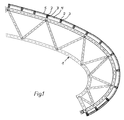
- 1 is a structure consisting of pipes as part of a building ledge denotes, which is curved in two directions, from Figure 1 shows only one direction of curvature.
- the structure can in particular be welded from the pipes.
- Stainless steel tubes arranged side by side as openwork cladding is generally designated 5.
- the stainless steel tubes are not individual shown because they are relatively close together with much shorter Intervals as the pipes of the structure are arranged; they run parallel to the neighboring pipes of the structure.
- FIG. 2 three short sections of the stainless steel tubes 6 to 8 are shown. They rest in approximately semicircular recesses 9 to 11 of a carrier plate 4, in which they are inserted.
- a clamp 12 is used to hold two adjacent stainless steel tubes, for example 6, 7, in each case, to which further similar clamps 13, 14 can be connected on the right.
- the clamps are mounted close together, so that a continuous impression is created, as shown in Figure 4 above.
- the clamps consist of an approximately inverted U-shaped sheet, see clamp 12 in FIG. 2 and in FIG. 5, from which recesses are formed at their ends essentially in the form of a quarter circle, which in FIG. 2 are 15, 16 are designated.
- the recesses 15, 16 of the clamp are also referred to as complementary recesses.
- the clamp 12 is drilled with aligned holes 17, 18 so that the clamp can be screwed into one of the holes 19 to 21 of the carrier plate, see FIGS. 4 and 5.
- the carrier plate are from these slots 22 to 25 in the horizontal direction formed, which are used for screwing to the support clamp 3.
- FIGS. 2 to 5 show how the carrier plate 4 is attached to an outer, arranged to a support tube opening 26 distant portion 27 of the support bracket 3 is.
- section 27 have two parallel support plate plates 28, 29, which the carrier plate 4 in the region of the elongated holes 22 to 25 include, also elongated holes 30 to 33, but oriented vertically are.
- the support plate 4 By screwing the support plate 4 to the support clamp plates 28, 29 in the elongated holes 22 to 25, 30 to 33 - the elongated holes in the rear Structure clamp plate 29 are not designated - can the support plate with the held in it stainless steel tubes 6 to 8 opposite the structural clamp 3 and the pipe of the structure not shown in FIGS. 2 to 5 to which the structural clamp is attached can be adjusted to the position of the stainless steel pipes 6 to 8 optimally adapt in the structure.
- the support clamp 3 is completed by a substantially U-shaped Structure receiving plate 34 with a tube recess 35, which together with complementary tube recesses 36, 37 of the supporting plate plates 28, 29 form the support tube opening 26 when the supporting structure receiving plate and the structural clamp plates, as shown in FIGS. 2 to 5, are put together.
- the support plate 28 and 29 and the Structure support plate 34 can include one in Figures 2 and 3 not shown tube of the structure are screwed together, where each screw by three consecutive, vertical in the drawing pass oriented elongated holes, of which only the front one Elongated hole of the upper support plate 28 in FIG. 2 with a reference number 38 or 39 or 40 or 41 is provided.
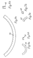
- the structure Before mounting on a pipe the structure is in the pipe recess 35 of the support plate 34 and in the complementary tube recesses 36, 37 of the supporting structure clamp plates 40, 41 these tube recesses compared to shorter rubber-elastic profile strips 42, 43, 44 made of EPDM rubber inserted, their circular segment-shaped course, for example using the profile strip 42 emerges from FIG. 8a and its approximately inverted U-shape Cross section of Figure 8b can be seen.
- the profile strip 42 is there shown larger than the tube recess 35 in Figure 2 and Figure 4.
- the supporting structure clamp plates 40, 41 provided with the profile strips 42 to 44 and structure support plate 34 are radial on a tube 2 of the structure aligned and with screws 45 to 48 through the elongated holes 38 to 41 reach through, screwed together, see Figure 4, in which the tube 2 of the Structure is not shown pinched for clarity.
- Supporting clamp plates 28, 29 are also screwed to the support plate 4, which, as indicated in Figure 4, extends laterally beyond the support bracket 3 and on several structural clamps analogous to the structural clamp 3 in can be mounted on one level.
- the distance between each two can cross neighboring structure clamps on one of the pipes of the structure typically be 3 to 31 ⁇ 2 m.
- the pre-assembled on the support plate 4 support bracket 3 is after this the tube 49 of the structure initially comprises loosely aligned so that the Structural clamp in the radial direction of the curved tube 2 and thus the Curvature of the building structure is aligned in this area.
- the neighboring ones Structural clamps can thus be arranged in a fan shape on the tube 2 his.
- each of the profile elements e.g. 61
- the shape of each of the profile elements is a side view of Figure 7a and can be seen in cross section from FIG. 7b.
- the profile element can be between the legs of the clamp bent from sheet metal, e.g. 12, be used.
Landscapes
- Engineering & Computer Science (AREA)
- Architecture (AREA)
- Physics & Mathematics (AREA)
- Electromagnetism (AREA)
- Civil Engineering (AREA)
- Structural Engineering (AREA)
- Clamps And Clips (AREA)
- Joining Of Building Structures In Genera (AREA)
- Roof Covering Using Slabs Or Stiff Sheets (AREA)
- Buffer Packaging (AREA)
- Wire Processing (AREA)
- Laminated Bodies (AREA)
Abstract
Description
- Figur 1
- in verkleinerter Darstellung eine Seitenansicht durch ein aus Rohren bestehendes Tragwerk mit Verkleidung, wobei das Tragwerk nicht nur in der dargestellten Zeichenebene gekrümmt ist, sondern auch im wesentlichen rechtwinklig dazu,
- Figur 2
- in schaubildlicher Ansicht eine Trägerplatte von drei verkürzt dargestellten Edelstahlrohren als Verkleidungselementen, wobei die Trägerplatte in ihrer Montagekonfiguration in einer Tragwerkschelle in noch nicht fixiertem Zustand dargestellt ist,
- Figur 3
- in einer Seitenansicht die Trägerplatte ohne Edelstahlrohre in der Tragwerkschelle in dem Zustand gemäß Figur 2,
- Figur 4
- eine Draufsicht auf die Trägerplatte mit Edelstahlrohren, die durch drei Schellen fixiert sind, wobei die Trägerplatte in der Tragwerkschelle verschraubt ist,
- Figur 5
- in einer Seitenansicht die Trägerplatte mit Schellen, jedoch ohne Edelstahlrohre, in der Tragwerkschelle verschraubt,
- Figur 6a
- eine Draufsicht auf ein elastisches Profilelement, welches zur Einlage in Ausnehmungen der Trägerplatte geeignet ist,
- Figur 6b
- einen Querschnitt durch das Profilelement nach Figur 6a,
- Figur 7a
- in einer Draufsicht ein Profilelement zum Einklemmen in eine Schelle,
- Figur 7b
- einen Querschnitt durch das Profilelement gemäß Figur 7a,
- Figur 8a
- eine Draufsicht auf einen gummielastischen Profilstreifen zur Einlage in eine Rohrausnehmung der Tragwerkschelle und
- Figur 8b
- einen Querschnitt durch den Profilstreifen nach Figur 8a.
Die Schellen bestehen in ihrer Grundausführung aus einem annähernd umgekehrt U-förmig gebogenen Blech, siehe Schelle 12 in Figur 2 und in Figur 5, aus dem an seinen Enden Ausnehmungen im wesentlichen in Form eines Viertelkreises ausgeformt sind, die in Figur 2 mit 15, 16 bezeichnet sind. Da jeweils zwei solcher Ausnehmungen, wenn sie benachbart sind, eine der Ausnehmungen, z.B. 9, der Trägerplatte annähernd kreisförmig ergänzen, sind die Ausnehmungen 15, 16 der Schelle auch als komplementäre Ausnehmungen bezeichnet. In der Mitte zwischen zwei Ausnehmungen 15, 16 ist die Schelle 12 mit fluchtenden Löchern 17, 18 durchbohrt, so daß die Schelle in einem der Löcher 19 bis 21 der Trägerplatte verschraubt werden kann, siehe Figuren 4 und 5.
- 1
- Tragwerk
- 2
- Rohre
- 3
- Tragwerkschellen
- 4
- Trägerplatte
- 5
- Edelstahlrohr
- 6
- Verkleidung
- 7
- Edelstahlrohr
- 8
- Edelstahlrohr
- 9
- Ausnehmung
- 10
- Ausnehmung
- 11
- Ausnehmung
- 12
- Schelle
- 13
- Schelle
- 14
- Schelle
- 15
- komplementäre Ausnehmung
- 16
- komplementäre Ausnehmung
- 17
- Loch der Schelle
- 18
- Loch der Schelle
- 19
- Loch der Trägerplatte
- 20
- Loch der Trägerplatte
- 21
- Loch der Trägerplatte
- 22
- Langloch
- 23
- Langloch
- 24
- Langloch
- 25
- Langloch
- 26
- Tragrohröffnung
- 27
- Abschnitt
- 28
- Tragwerkschellenplatte
- 29
- Tragwerkschellenplatte
- 30
- Langloch
- 31
- Langloch
- 32
- Langloch
- 33
- Langloch
- 34
- Tragwerkaufnahmeplatte
- 35
- Rohrausnehmung
- 36
- komplementäre Rohrausnehmung
- 37
- komplementäre Rohrausnehmung
- 38
- Langloch
- 39
- Langloch
- 40
- Langloch
- 41
- Langloch
- 42
- Profilstreifen
- 43
- Profilstreifen
- 44
- Profilstreifen
- 45
- Schrauben
- 46
- Schrauben
- 47
- Schrauben
- 48
- Schrauben
- 49
- -
- 50
- Schrauben
- 51
- Schrauben
- 52
- Schrauben
- 53
- Schrauben
- 54
- Langloch
- 55
- Profilelemente
- 56
- Profilelemente
- 57
- Profilelemente
- 58
- komplementäre Ausnehmungen
- 59
- komplementäre Ausnehmungen
- 60
- komplementäre Ausnehmungen
- 61
- Profilelement
- 62
- Profilelement
- 63
- Profilelement
- 64
- Profilelement
- 65
- Profilelement
Claims (16)
- Aus Rundmetallstäben gebildete durchbrochene Verkleidung (6) von Bauwerkteilen mit in Längsrichtung der Rundmaterialstäbe beabstandet angeordneten Trägerplatten (4), aus denen jeweils längs einer Kante in Querabständen zueinander angeordnete, an der Kante offene, im wesentlichen kreissegmentförmige Ausnehmungen (9 bis 11) ausgeformt sind, wobei die Rundmaterialstäbe in die Ausnehmungen eingeklemmt sind,
dadurch gekennzeichnet, daß eine zwei benachbarte Ausnehmungen (9, 10 bzw. 10, 11) zumindest teilweise übergreifende Schelle (12, 13, 14) nur an einer Montagestelle zwischen den beiden Ausnehmungen gelagert und nach Einstellung von der Schelle (12, 13, 14) auf zwei in die Ausnehmungen (9 bis 11) eingelegte Rundmaterialstäbe ausgeübter und im wesentlichen gleicher Klemmkräfte fixierbar ist. - Verkleidung nach Anspruch 1,
dadurch gekennzeichnet, daß die Montagestelle der Schelle (12, 13, 14) durch ein Loch (19, 20, 21) in der Trägerplatte (4) realisiert ist. - Verkleidung nach Anspruch 1 oder 2,
dadurch gekennzeichnet, daß mehrere Schellen (12 bis 14) entlang den Ausnehmungen (9 bis 11) aus der Trägerplatte (4) so in einer Reihe nebeneinander angeordnet sind, daß benachbarte Enden je zweier Schellen (12, 13 bzw. 13, 14) je eine der Ausnehmungen (9 bis 11) annähernd hälftig überdecken. - Verkleidung nach einem der Ansprüche 1 bis 3,
dadurch gekennzeichnet, daß die Schelle (12 bis 14) an jedem ihrer Enden eine Ausnehmung (15, 16, 58 bis 60) im wesentlichen in Form eines Viertelkreissegments aufweist, welches zu der Ausnehmung (9 bis 11) aus der Trägerplatte (4) komplementär ist. - Verkleidung nach Anspruch 1 oder 2,
dadurch gekennzeichnet, daß eines der beiden Enden der Schelle eine Ausnehmung im wesentlichen in Form eines Halbkreissegments aufweist, welches zu der Ausnehmung aus der Trägerplatte komplementär ist. - Verkleidung nach einem der vorangehenden Ansprüche,
dadurch gekennzeichnet, daß mit den Schellen (12 bis 14) eine so große Klemmkraft auf die Rundmaterialstäbe eingestellt ist, daß diese verdrehbar und insbesondere bei Wärmeausdehnung in den Ausnehmungen (9 bis 10) der Trägerplatten (4) in Längsrichtung der Rundmaterialstäbe verschiebbar sind. - Verkleidung nach einem der vorangehenden Ansprüche,
dadurch gekennzeichnet, daß die Schellen (12 bis 14) an die Trägerplatte (4) angeschraubt sind. - Verkleidung nach einem der vorangehenden Ansprüche,
dadurch gekennzeichnet, daß zur Verkleidung von zweifach gekrümmten Bauwerkteilen die Trägerplatten (4) radial zu einer der Krümmungen ausgerichtet sind. - Verkleidung nach einem der vorangehenden Ansprüche,
dadurch gekennzeichnet, daß zwischen den Ausnehmungen (9 bis 11, 58 bis 60) der Trägerplatten (4) und der Schellen (12, 13, 14) einerseits und den eingeklemmten Rundmaterialstäben andererseits gummielastische Profilelemente (55 bis 58, 61 bis 65) angeordnet sind. - Verkleidung nach Anspruch 9,
dadurch gekennzeichnet, daß die gummielastischen Profilelemente (55 bis 57, 61 bis 65) aus EPDM-Gummi formgespritzt sind. - Verkleidung nach Anspruch 9 oder 10,
dadurch gekennzeichnet, daß die gummielastischen Profilelemente (55 bis 57, 61 bis 65) kreissegmentförmig sind. - Verkleidung nach einem der vorangehenden Ansprüche,
dadurch gekennzeichnet, daß die Schelle (12, 13, 14) aus Blech im Querschnitt im wesentlichen umgekehrt U-förmig mit zwei im wesentlichen formgleichen Schellenschenkeln gebogen ist, zwischen denen an Rändern der Ausnehmungen (15, 16, 58 bis 60) die Profilelemente (61 bis 65) eingeschlossen sind und zwischen denen die Trägerplatte (4) gesteckt ist, die an der einen Montagestelle mit den Schellenschenkeln zusammengeschraubt ist. - Verkleidung nach einem der vorangehenden Ansprüche,
dadurch gekennzeichnet, daß die Trägerplatte (4) in einem von den Ausnehmungen (15, 16, 58 bis 60) entfernten Abschnitt Langlöcher (22 bis 25; 54) zur Anbringung an einer Tragwerkschelle (3) aufweist, die an ein aus Rohren bestehendes Tragwerk (1) klemmbar ist. - Verkleidung nach Anspruch 13,
dadurch gekennzeichnet, daß die Tragwerkschelle (3) ein Paket zweier Tragwerkschellenplatten (28, 29) mit je einer komplementären Rohrausnehmung (36, 37) umfaßt, die unter Einschluß von Schenkeln einer im wesentlichen U-förmigen Tragwerkaufnahmeplatte (34) und eines Rohrs (2) zusammenschraubbar sind und daß die beiden Tragwerkschellenplatten (28, 29) Langlöcher (30 bis 33) zur Verbindung mit der zwischen ihnen eingeschlossenen Trägerplatte (4) aufweisen. - Verkleidung nach Anspruch 14,
dadurch gekennzeichnet, daß die Rohrausnehmung (35) und die komplementären Rohrausnehmungen (36, 37) der Tragwerkschelle (3) in gummielastische Profilstreifen (42 bis 44) eingefaßt sind. - Verkleidung nach einem der vorangehenden Ansprüche,
gekennzeichnet durch
Edelstahlrohre (6 bis 8) mit glatten Außenwänden als Rundmaterialstäbe.
Applications Claiming Priority (2)
| Application Number | Priority Date | Filing Date | Title |
|---|---|---|---|
| DE20208145U DE20208145U1 (de) | 2002-05-24 | 2002-05-24 | Aus Rundmaterialstäben gebildete durchbrochene Verkleidung von Bauwerksteilen |
| DE20208145U | 2002-05-24 |
Publications (2)
| Publication Number | Publication Date |
|---|---|
| EP1365084A1 true EP1365084A1 (de) | 2003-11-26 |
| EP1365084B1 EP1365084B1 (de) | 2009-11-04 |
Family
ID=7971496
Family Applications (1)
| Application Number | Title | Priority Date | Filing Date |
|---|---|---|---|
| EP03011695A Expired - Lifetime EP1365084B1 (de) | 2002-05-24 | 2003-05-23 | Aus Rundmaterialstäben gebildete durchbrochene Verkleidung von Bauwerkteilen |
Country Status (3)
| Country | Link |
|---|---|
| EP (1) | EP1365084B1 (de) |
| AT (1) | ATE447649T1 (de) |
| DE (2) | DE20208145U1 (de) |
Families Citing this family (2)
| Publication number | Priority date | Publication date | Assignee | Title |
|---|---|---|---|---|
| DE20309902U1 (de) * | 2003-06-26 | 2003-09-25 | Arnold AG, 61381 Friedrichsdorf | Aus Stäben gebildete Verkleidung von Decken, Wänden o.dgl. Bauwerkteilen |
| DE102019002578A1 (de) * | 2019-04-09 | 2020-10-15 | Stobag Ag | Überdachung in Form einer Pergola, eines Glasdachs oder eines Wintergartens |
Citations (5)
| Publication number | Priority date | Publication date | Assignee | Title |
|---|---|---|---|---|
| DE718025C (de) * | 1939-01-18 | 1942-02-28 | Krimhilde Schlitt | Isolierstoffschelle |
| US3437297A (en) * | 1965-09-14 | 1969-04-08 | Anger Kunststoff | Support members for pipes |
| GB1329503A (en) * | 1971-06-01 | 1973-09-12 | Ramcor Inc | Jaw member for a composite clamp |
| US4224721A (en) | 1977-03-28 | 1980-09-30 | Ohlson Kurt L | Device for clamping two generally parallel directed members |
| DE29817115U1 (de) * | 1998-09-24 | 1999-01-07 | Arnold GmbH, 61381 Friedrichsdorf | Aus Stäben, insbesondere Rundmaterial, gebildete Verkleidung von Decken |
Family Cites Families (2)
| Publication number | Priority date | Publication date | Assignee | Title |
|---|---|---|---|---|
| US3934802A (en) | 1974-11-04 | 1976-01-27 | Illinois Tool Works Inc. | Tube clamping fastener |
| DE19739824C1 (de) | 1997-09-11 | 1999-05-27 | Hydac Befestigungstechnik Gmbh | Befestigungssystem mit Bajonettverschluß |
-
2002
- 2002-05-24 DE DE20208145U patent/DE20208145U1/de not_active Expired - Lifetime
-
2003
- 2003-05-23 EP EP03011695A patent/EP1365084B1/de not_active Expired - Lifetime
- 2003-05-23 DE DE50312082T patent/DE50312082D1/de not_active Expired - Lifetime
- 2003-05-23 AT AT03011695T patent/ATE447649T1/de active
Patent Citations (5)
| Publication number | Priority date | Publication date | Assignee | Title |
|---|---|---|---|---|
| DE718025C (de) * | 1939-01-18 | 1942-02-28 | Krimhilde Schlitt | Isolierstoffschelle |
| US3437297A (en) * | 1965-09-14 | 1969-04-08 | Anger Kunststoff | Support members for pipes |
| GB1329503A (en) * | 1971-06-01 | 1973-09-12 | Ramcor Inc | Jaw member for a composite clamp |
| US4224721A (en) | 1977-03-28 | 1980-09-30 | Ohlson Kurt L | Device for clamping two generally parallel directed members |
| DE29817115U1 (de) * | 1998-09-24 | 1999-01-07 | Arnold GmbH, 61381 Friedrichsdorf | Aus Stäben, insbesondere Rundmaterial, gebildete Verkleidung von Decken |
Also Published As
| Publication number | Publication date |
|---|---|
| ATE447649T1 (de) | 2009-11-15 |
| EP1365084B1 (de) | 2009-11-04 |
| DE20208145U1 (de) | 2002-08-14 |
| DE50312082D1 (de) | 2009-12-17 |
Similar Documents
| Publication | Publication Date | Title |
|---|---|---|
| DE3606112C2 (de) | Tragschiene für Unterdecken | |
| EP0531869A2 (de) | Montageklemme | |
| EP1561956A1 (de) | Verbindungsvorrichtung | |
| DE2846110C3 (de) | Kardierplatte | |
| DE8019598U1 (de) | Klammer zum Befestigen von Fußboden-Heizungsrohren | |
| DE202005006528U1 (de) | Befestigungsprofil | |
| DE69210796T3 (de) | Klammer, insbesondere zur Befestigung von Heizkörpern | |
| EP4053469A1 (de) | Traggestell zu einer schrägen befestigung eines solarmoduls auf einem dach | |
| DE10018658B4 (de) | Rundschalungsmodul | |
| DE2537244A1 (de) | Zaun | |
| DE2923903C2 (de) | ||
| AT402834B (de) | Verstellbarer firstlattenhalter für eine dachstuhlkonstruktion | |
| EP1365084B1 (de) | Aus Rundmaterialstäben gebildete durchbrochene Verkleidung von Bauwerkteilen | |
| EP0033904B1 (de) | Metallklammer für Wand- und Deckenverkleidungen | |
| DE2335916C2 (de) | Lamellenträgerelement zur Verwendung für Sonnenschutzschirme oder für Fassadenverkleidungen | |
| AT396379B (de) | Dacheindeckung aus nebeneinanderliegend angeordneten blechtafeln | |
| DE2118419C3 (de) | Treppengeländer | |
| DE8701832U1 (de) | Scharnierelement | |
| DE3545917C2 (de) | ||
| DE29516040U1 (de) | Tragstütze sowie Tragvorrichtung mit wenigstens vier im Abstand zueinander angeordneten Tragstützen | |
| EP1878842B1 (de) | Aus Stäben gebildete Verkleidung von Decken, Wänden oder dergleichen Bauwerkteilen | |
| DE9306127U1 (de) | Geräteeinbaudose für Installationskanäle | |
| DE4143114C2 (de) | Zaun und Vorrichtung zum Verbinden von Zaunmatten | |
| DE60000313T2 (de) | Befestigungssystem an einer Säule für ein Trägerelement | |
| CH671082A5 (de) |
Legal Events
| Date | Code | Title | Description |
|---|---|---|---|
| PUAI | Public reference made under article 153(3) epc to a published international application that has entered the european phase |
Free format text: ORIGINAL CODE: 0009012 |
|
| 17P | Request for examination filed |
Effective date: 20030828 |
|
| AK | Designated contracting states |
Kind code of ref document: A1 Designated state(s): AT BE BG CH CY CZ DE DK EE ES FI FR GB GR HU IE IT LI LU MC NL PT RO SE SI SK TR |
|
| AX | Request for extension of the european patent |
Extension state: AL LT LV MK |
|
| AKX | Designation fees paid |
Designated state(s): AT CH DE GB LI |
|
| 17Q | First examination report despatched |
Effective date: 20070927 |
|
| GRAP | Despatch of communication of intention to grant a patent |
Free format text: ORIGINAL CODE: EPIDOSNIGR1 |
|
| GRAC | Information related to communication of intention to grant a patent modified |
Free format text: ORIGINAL CODE: EPIDOSCIGR1 |
|
| GRAS | Grant fee paid |
Free format text: ORIGINAL CODE: EPIDOSNIGR3 |
|
| GRAA | (expected) grant |
Free format text: ORIGINAL CODE: 0009210 |
|
| AK | Designated contracting states |
Kind code of ref document: B1 Designated state(s): AT CH DE GB LI |
|
| REG | Reference to a national code |
Ref country code: GB Ref legal event code: FG4D Free format text: NOT ENGLISH |
|
| REG | Reference to a national code |
Ref country code: CH Ref legal event code: NV Representative=s name: BOHEST AG Ref country code: CH Ref legal event code: EP |
|
| REF | Corresponds to: |
Ref document number: 50312082 Country of ref document: DE Date of ref document: 20091217 Kind code of ref document: P |
|
| PLBE | No opposition filed within time limit |
Free format text: ORIGINAL CODE: 0009261 |
|
| STAA | Information on the status of an ep patent application or granted ep patent |
Free format text: STATUS: NO OPPOSITION FILED WITHIN TIME LIMIT |
|
| 26N | No opposition filed |
Effective date: 20100805 |
|
| REG | Reference to a national code |
Ref country code: CH Ref legal event code: PCAR Free format text: NEW ADDRESS: HOLBEINSTRASSE 36-38, 4051 BASEL (CH) |
|
| PGFP | Annual fee paid to national office [announced via postgrant information from national office to epo] |
Ref country code: AT Payment date: 20140528 Year of fee payment: 12 |
|
| PGFP | Annual fee paid to national office [announced via postgrant information from national office to epo] |
Ref country code: CH Payment date: 20150516 Year of fee payment: 13 Ref country code: GB Payment date: 20150518 Year of fee payment: 13 Ref country code: DE Payment date: 20150518 Year of fee payment: 13 |
|
| REG | Reference to a national code |
Ref country code: AT Ref legal event code: MM01 Ref document number: 447649 Country of ref document: AT Kind code of ref document: T Effective date: 20150523 |
|
| PG25 | Lapsed in a contracting state [announced via postgrant information from national office to epo] |
Ref country code: AT Free format text: LAPSE BECAUSE OF NON-PAYMENT OF DUE FEES Effective date: 20150523 |
|
| REG | Reference to a national code |
Ref country code: DE Ref legal event code: R119 Ref document number: 50312082 Country of ref document: DE |
|
| REG | Reference to a national code |
Ref country code: CH Ref legal event code: PL |
|
| GBPC | Gb: european patent ceased through non-payment of renewal fee |
Effective date: 20160523 |
|
| PG25 | Lapsed in a contracting state [announced via postgrant information from national office to epo] |
Ref country code: CH Free format text: LAPSE BECAUSE OF NON-PAYMENT OF DUE FEES Effective date: 20160531 Ref country code: LI Free format text: LAPSE BECAUSE OF NON-PAYMENT OF DUE FEES Effective date: 20160531 |
|
| PG25 | Lapsed in a contracting state [announced via postgrant information from national office to epo] |
Ref country code: DE Free format text: LAPSE BECAUSE OF NON-PAYMENT OF DUE FEES Effective date: 20161201 |
|
| PG25 | Lapsed in a contracting state [announced via postgrant information from national office to epo] |
Ref country code: GB Free format text: LAPSE BECAUSE OF NON-PAYMENT OF DUE FEES Effective date: 20160523 |