EP1365084B1 - Revêtement ajouré pour parties de bâtiment composé de barres à section circulaire - Google Patents
Revêtement ajouré pour parties de bâtiment composé de barres à section circulaire Download PDFInfo
- Publication number
- EP1365084B1 EP1365084B1 EP03011695A EP03011695A EP1365084B1 EP 1365084 B1 EP1365084 B1 EP 1365084B1 EP 03011695 A EP03011695 A EP 03011695A EP 03011695 A EP03011695 A EP 03011695A EP 1365084 B1 EP1365084 B1 EP 1365084B1
- Authority
- EP
- European Patent Office
- Prior art keywords
- clamp
- recesses
- round bars
- cladding according
- open work
- Prior art date
- Legal status (The legal status is an assumption and is not a legal conclusion. Google has not performed a legal analysis and makes no representation as to the accuracy of the status listed.)
- Expired - Lifetime
Links
Images



Classifications
-
- E—FIXED CONSTRUCTIONS
- E04—BUILDING
- E04B—GENERAL BUILDING CONSTRUCTIONS; WALLS, e.g. PARTITIONS; ROOFS; FLOORS; CEILINGS; INSULATION OR OTHER PROTECTION OF BUILDINGS
- E04B7/00—Roofs; Roof construction with regard to insulation
- E04B7/08—Vaulted roofs
- E04B7/10—Shell structures, e.g. of hyperbolic-parabolic shape; Grid-like formations acting as shell structures; Folded structures
- E04B7/105—Grid-like structures
-
- E—FIXED CONSTRUCTIONS
- E04—BUILDING
- E04F—FINISHING WORK ON BUILDINGS, e.g. STAIRS, FLOORS
- E04F13/00—Coverings or linings, e.g. for walls or ceilings
- E04F13/07—Coverings or linings, e.g. for walls or ceilings composed of covering or lining elements; Sub-structures therefor; Fastening means therefor
- E04F13/08—Coverings or linings, e.g. for walls or ceilings composed of covering or lining elements; Sub-structures therefor; Fastening means therefor composed of a plurality of similar covering or lining elements
- E04F13/0801—Separate fastening elements
Definitions
- the invention relates to an openwork panel of structural parts formed from round material rods according to the preamble of claim 1
- the structural parts are in particular structures consisting of pipes, which are curved in two directions, that is, have at least two radii of curvature.
- Such structures may in particular be designed as roof stems and, for example, have wing-like profiles that also curve over the ground plan, i. arcuate, can run.
- cladding in particular planar building parts, such as ceilings, walls, already includes a made of rods, in particular round material cladding to the prior art, which in this case allows for easy installation and mounted aesthetically very appealing ( DE-U-298 17 115 ).
- rods in particular round material cladding to the prior art, which in this case allows for easy installation and mounted aesthetically very appealing ( DE-U-298 17 115 ).
- at least three support plates are each provided with at least one row of mutually spaced transversely spaced recesses whose profiles are substantially identical to the cross sections of the rods are.
- the recesses are open on one side.
- the transverse distances of the recesses are equidistant in the first carrier plate and in the third carrier plate.
- the transverse distances of the recesses in the second carrier plate are, based on the equidistant transverse distances, by a difference greater or less than these.
- the support plates are arranged parallel to each other, in such a way that the recesses of the first support plate and the third support plate are aligned and the recesses of the second support plate are offset by the difference measure.
- the rods lying in the recesses are clamped.
- this clamping does not ensure a specific rotation and longitudinal displacement of the rods during assembly to adapt to a curvature of the building part or a change in length of the rods due to temperature influences.
- the counterpart in the longitudinal direction of the two recesses is rotated away from them and for clamping the counterpart is rotated transversely to the inserted metal tubes.
- An axis of rotation of the counterpart is arranged essentially at right angles to longitudinal axes of the recesses or of the metal tubes received by them.
- the flat counterpart is formed with two inclined planar surfaces which extend on both sides of the axis of rotation.
- the axis of rotation may be formed by a pin in one of the two parts of the clamping device and a pin receiving hole in the other part.
- the pin and the hole are partially elliptical shaped so that they can be assembled in a mutual rotational position.
- the counterpart despite complicated shape of the hole and the pin is not pivotally as a whole about an axis which extends in the longitudinal direction of the metal tubes.
- the present invention is therefore an object of the invention to provide a formed of round rods rods openwork of building parts largely arbitrary curvatures, which is characterized by simple installation, good adaptation to the curvature of the building parts and constancy of the surface shape of the panel even at temperature expansion.
- carrier plates in which the arrangement of the recesses corresponds to a first curvature of the building part to be covered, ie, is approximately equal.
- the support plate formed in this way are then not parallel to each other according to a second curvature of the structural part to be clad, but aligned in the radial direction of this curvature, in particular its center in the case of a circular arc curvature, see claim 7.
- the round rods are clamped only with such a clamping force in that they twist during assembly and in particular when there is thermal expansion in the recesses the carrier plates in the longitudinal direction of the round material rods can move.
- the round material rods can individually adjust to one of the curvatures of the building part.
- the clamping of the round rods in each two adjacent recesses of the support plate is carried out with a clamp, preferably with two complementary to the recesses of the support plate recesses.
- the clamp is preferably screwed to the support plate in a hole or a bore, which forms a single mounting point between the recesses.
- the desired clamping prestressing according to claim 8 is advantageously achieved by rubber-elastic profile elements, which are arranged between the recesses of the carrier plates and the clamps on the one hand and the clamped round bars on the other.
- the rubber-elastic profile elements may be injection molded in the mold, which is essentially determined by the recesses, and with the desired EPDM rubber cross-section.
- the recesses of the carrier plates and the clamps and accordingly the rubber-elastic profile elements are in particular according to claim 10 circular arc.
- Two clamps screwed next to one another on the carrier plate complement each other for holding a round material bar in one of the recesses of the carrier plate.
- the recess of the clamps can also extend over approximately a semicircle, so that this one carrier plate completely covers a round material rod over the recess on the carrier plate.
- the arrangement of the clamps next to each other along one edge of the carrier plate, and by the abutting circular arc-shaped recesses a largely closed overall impression is achieved.
- the clamp is bent according to claim 11 of sheet metal, with substantially identical clamp legs, including the rubber-elastic profile elements at the edges of the recesses and the round rods between the recesses of the clamps and the support plate to a central Hole between two adjacent recesses of the support plate are screwed to this according to claim 6.
- the support plate according to claim 12 in a remote from the recesses section slots which are mounted on a frame clamp.
- the structural clamp is suitable in the present case, to be clamped to the existing structure of pipes.
- the framework clamp is also formed in a production-favorable manner according to claim 13 as a package of two structural clamp plates, each with a complementary pipe recess, including the inclusion of Legs of a substantially U-shaped support frame receiving plate and a tube can be screwed together.
- the two clamp plates also have slots for connection with the enclosed between them support plate.
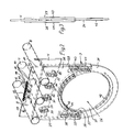
- FIG. 1 a tubular structure as part of a building projection, which is curved in two directions, wherein FIG. 1 only one direction of curvature is visible.
- the structure can be welded in particular from the tubes.
- On pipes 2, which are in FIG. 1 are shown cut in the plane of the drawing and initially perpendicular to the section plane, but curved to this, are clamped clamps 3, which are bolted to support plates 4.
- the support plates carry juxtaposed stainless steel tubes as a perforated cladding, which is generally denoted by 5.
- the stainless steel tubes are not shown individually because they are relatively close together with much shorter intervals than the tubes of the structure are arranged; they run parallel to the adjacent pipes of the structure.
- FIG. 2 three short sections of the stainless steel tubes 6 to 8 are shown. They rest in approximately semicircular recesses 9 to 11 of a support plate 4, in which they are inserted.
- a clamp 12 for clamping holding two adjacent each Stainless steel tubes, eg 6, 7, serves a clamp 12 to which more similar clamps 13, 14 can connect to the right.
- the clamps are mounted close to each other, so that a continuous impression arises, as in FIG. 4 shown above.
- the clamps consist in their basic version of an approximately inverted U-shaped bent sheet metal, see clamp 12 in FIG. 2 and in FIG. 5 , are formed from the recesses at its ends substantially in the form of a quarter circle, the in FIG. 2 are designated 15, 16.
- the recesses 15, 16 of the clamp are also referred to as complementary recesses.
- the clamp 12 is pierced with aligned holes 17, 18, so that the clamp can be screwed into one of the holes 19 to 21 of the support plate, see FIGS. 4 and 5 ,
- At one of the open-topped recesses 9 to 11 remote portion of the support plate are formed from these slots 22 to 25 in the horizontal direction, which serve for screwing to the supporting frame clamp 3.
- FIGS. 2 to 5 is shown as the support plate 4 is disposed on an outer, to a support tube opening 26 remote portion 27 of the support frame 3.
- two parallel structural clamp plates 28, 29, which include the support plate 4 in the region of the slots 22 to 25, also elongated holes 30 to 33, which are, however, oriented vertically.
- the slots in the rear support plate clamp 29 are not designated - can the support plate with held in it stainless steel tubes 6 to 8 relative to the support frame 3 and the pipe in the FIGS. 2 to 5 not prepared pipe of the structure to which the structural clamp is attached, to be adjusted to optimally adjust the position of the stainless steel tubes 6 to 8 in the structure.
- the structural clamp 3 is completed by a substantially U-shaped support receiving plate 34 having a Rohraus Principleung 35, which together with complementary tube recesses 36, 37 of the structural clamp plates 28, 29 form the support tube opening 26, when the supporting structure receiving plate and the supporting clamp plates, as in the FIGS. 2 to 5 shown, are plugged together.
- the structural clamp plates 28 and 29 and the support receiving plate 34 may include one in the FIGS. 2 and 3 not shown tube of the structure are bolted together, each screw passing through three consecutive, vertically oriented in the drawing slots, of which only the foremost slot in FIG. 2 upper structural clamp plate 28 is provided with reference numerals 38 and 39 or 40 and 41, respectively.
- FIG. 8a Prior to mounting on a pipe of the structure are in the pipe recess 35 of the support receiving plate 34 and in the complementary tube recesses 36, 37 of the structural clamp plates 40, 41 these tube recesses against shorter rubber-elastic profile strips 42, 43, 44 inserted from EPDM rubber whose circular segment-shaped course, for example, based on the profile strip 42 FIG. 8a emerges and their approximately inverted U-shaped cross-section FIG. 8b is apparent.
- the profile strip 42 is shown larger than the pipe recess 35 in FIG. 2 respectively.
- FIG. 4
- structural clamp plates 40, 41 and support mounting plate 34 are radially aligned on a pipe 2 of the structure and screwed together with screws 45 to 48, which extend through the slots 38 to 41, see FIG. 4 in which the tube 2 of the structure is not shown clamped for clarity.
- the support plate 4 is further screwed, which, as in FIG. 4 indicated, extends laterally beyond the structural clamp 3 and can be mounted on a plurality of structural clamps analogous to the structural clamp 3 in a plane. Transversely, the distance between each two each adjacent structural clamps on one of the tubes of the structure typically be 3 to 31 ⁇ 2 m.
- FIG. 4 can also be seen how the recesses 9 to 11 may be provided at the top of the support plate 4 with circular-segment-shaped rubber-elastic profile elements 55 to 57 made of EPDM rubber in plan view.
- One of these profile elements 55 is in FIG. 6a bigger in a top view and in FIG. 6b shown in cross section.
- the profile elements may be cast on the carrier plate.
- the preassembled on the support plate 4 structural clamp 3, after the first comprises the tube 49 of the structure loosely, aligned so that the support frame is aligned in the radial direction of the curved tube 2 and thus the curvature of the building structure in this area.
- the adjacent structural clamps can thus be arranged fan-shaped on the tube 2. Another curvature of the structural part or of the structure 1 in the region of the tube 2 is taken into account by the arrangement of the recesses 9 to 11 in the support plate 4.
- the stainless steel tubes 6 to 8 After mounting the truss clamp 3 with the support plate 4 on one of the tubes 2 of the structure and mounting other structural clamps on adjacent pipes of the structure, the same Bear support plate 4 or a flush with this support plate, the stainless steel tubes 6 to 8 inserted into the recesses 9 to 11 and in these under defined uniform clamping pressure, which is exerted by the first to the screws 66 to 68 pivotable clamps 12 to 14 on them , to be assembled.
- the stainless steel tubes take on the curvature according to the divergence or convergence of the arrangement of the structural clamps 3.
- the clamps are provided at their complementary recesses 15, 16, 58 to 60 with the rubber-elastic profile elements 61 to 65, see FIG.
- each of the profile elements eg 61
- the shape of each of the profile elements, eg 61, is in side view Figure 7a and in cross section from the FIG. 7b seen.
- the profile element can be inserted between the legs of the clamp bent from sheet metal, for example 12.
Landscapes
- Engineering & Computer Science (AREA)
- Architecture (AREA)
- Physics & Mathematics (AREA)
- Electromagnetism (AREA)
- Civil Engineering (AREA)
- Structural Engineering (AREA)
- Clamps And Clips (AREA)
- Wire Processing (AREA)
- Laminated Bodies (AREA)
- Joining Of Building Structures In Genera (AREA)
- Roof Covering Using Slabs Or Stiff Sheets (AREA)
- Buffer Packaging (AREA)
Claims (15)
- Revêtement ajouré (5) composé de barres de section circulaire (6 à 8) pour des éléments de construction, comportant des plaques de support (4), disposées à distance dans la direction longitudinale des barres de section circulaire (6 à 8), dans lesquelles sont formés des évidements (9 à 11), disposés respectivement le long d'un bord selon un écart transversal les uns par rapport aux autres, ouverts sur le bord et sensiblement en forme de segments circulaires, les barres de section circulaire étant serrées dans les évidements, caractérisé en ce qu'un collier de serrage (12, 13, 14) recouvrant au moins partiellement deux évidements adjacents (9, 10 ou 10, 11) est logé entre les deux évidements seulement au niveau d'un emplacement de montage, et, après ajustement, peut être fixé par des forces de serrage exercées par le collier de serrage (12, 13, 14) sur deux barres de section circulaire (6 à 8) insérées dans les évidements (9 à 11) et sensiblement équivalentes, en ce que l'emplacement de montage du collier de serrage (12, 13, 14) est conçu sous forme d'un trou ou d'un alésage (19, 20, 21) dans la plaque de support (4) qui s'étend dans le sens longitudinal des barres de section circulaire (6 à 8), en ce qu'un élément de fixation, de préférence une vis (66, 67, 68), est prévu dans le trou ou l'alésage (19, 20,21), et en ce que le collier de serrage (12, 13, 14) peut pivoter autour de l'emplacement de montage formé par l'alésage (19, 20, 21) et la vis (66, 67, 68), jusqu'à ce qu'il exerce sur les barres de section circulaire (6 à 8) une pression uniforme au niveau de leurs extrémités.
- Revêtement selon la revendication 1, caractérisé en ce que plusieurs colliers de serrage (12 à 14) sont disposés le long des évidements (9 à 11) de la plaque de support (4) alignés les uns à la suite des autres de sorte que des extrémités adjacentes de chaque paire de collier (12, 13 ou 13, 14) recouvrent respectivement l'un des évidements (9 à 11) approximativement de moitié.
- Revêtement selon la revendication 1 ou 2, caractérisé en ce que le collier de serrage (12 à 14) comporte à chacune de ses extrémités un évidement (15, 16, 58 à 60) qui a sensiblement la forme d'un segment en quart de cercle et qui est complémentaire de l'évidement (9 à 11) de la plaque de support (4).
- Revêtement selon la revendication 1 ou 2, caractérisé en ce que l'une des deux extrémités du collier de serrage comporte un évidement qui a sensiblement la forme d'un segment semi-circulaire et qui est complémentaire de l'évidement de la plaque de support.
- Revêtement selon l'une des revendications précédentes, caractérisé en ce que les colliers de serrage (12 à 14) permettent d'ajuster sur les barres de section circulaire une force de serrage importante au point que celles-ci peuvent être tordues et, en particulier en cas de dilatation thermique, peuvent être déplacées dans un plan longitudinal des barres de section circulaire dans les évidements (9 et 10) des plaques de support (4).
- Revêtement selon l'une des revendications précédentes, caractérisé en ce que les colliers de serrage (12 à 14) sont vissés à la plaque de support (4).
- Revêtement selon l'une des revendications précédentes, caractérisé en ce que pour le revêtement d'éléments de construction doublement cintrés, les plaques de support (4) sont orientées radialement à l'une des courbures.
- Revêtement selon l'une des revendications précédentes, caractérisé en ce que des éléments profilés élastiques (55 à 57, 61 à 65) sont disposés entre les évidements (9 à 11, 58 à 60) des plaques de support (4) et les colliers de serrage (12, 13, 14) d'une part et les barres de section circulaire serrées d'autre part.
- Revêtement selon la revendication 8, caractérisé en ce que les éléments profilés élastiques (55 à 57, 61 à 65) sont moulés par injection dans un caoutchouc EPDM.
- Revêtement selon la revendication 8 ou 9, caractérisé en ce que les éléments profilés élastiques (55 à 57, 61 à 65) sont en forme de segments circulaires.
- Revêtement selon l'une des revendications précédentes, caractérisé en ce que le collier de serrage (12, 13,14) en tôle, vu en coupe transversale, est cintré avec une forme sensiblement en U inversé ayant deux branches de collier de forme sensiblement identique, entre lesquelles les éléments profilés (61 à 65) sont enfermés au niveau des bords des évidements (15, 16, 58 à 60) et entre lesquelles est enfoncée la plaque de support (4), qui est vissée sur l'un des emplacements de montage avec les branches du collier de serrage.
- Revêtement selon l'une des revendications précédentes, caractérisé en ce que la plaque de support (4) comporte dans un segment distant des évidements (15, 16, 58 à 60) des trous oblongs (22 à 25 ; 54) pour le raccordement à un collier-support (3) qui peut être serré sur une structure porteuse (1) constituée de tubes.
- Revêtement selon la revendication 12, caractérisé en ce que le collier-support (3) comporte un ensemble de deux plaques de serrage de structure porteuse (28, 29) comprenant chacune un évidement tubulaire complémentaire (36, 37) qui, en refermant des branches d'une plaque support de structure porteuse sensiblement en U (34) et un tube (2), peuvent être vissées entre elles, et en ce que les deux plaques de serrage de structure porteuse (28, 29) comportent des trous oblongs (30 à 33) pour le raccordement à la plaque de support (4) insérée entre elles.
- Revêtement selon la revendication 13, caractérisé en ce que l'évidement tubulaire (35) et les évidements tubulaires complémentaires (36, 37) du collier-support (3) sont enserrés dans des bandes profilées élastiques (42 à 44).
- Revêtement selon l'une des revendications précédentes, caractérisé par des tubes en acier inoxydable (6 à 8) pourvus de parois extérieures lisses en tant que barres de section circulaire.
Applications Claiming Priority (2)
| Application Number | Priority Date | Filing Date | Title |
|---|---|---|---|
| DE20208145U DE20208145U1 (de) | 2002-05-24 | 2002-05-24 | Aus Rundmaterialstäben gebildete durchbrochene Verkleidung von Bauwerksteilen |
| DE20208145U | 2002-05-24 |
Publications (2)
| Publication Number | Publication Date |
|---|---|
| EP1365084A1 EP1365084A1 (fr) | 2003-11-26 |
| EP1365084B1 true EP1365084B1 (fr) | 2009-11-04 |
Family
ID=7971496
Family Applications (1)
| Application Number | Title | Priority Date | Filing Date |
|---|---|---|---|
| EP03011695A Expired - Lifetime EP1365084B1 (fr) | 2002-05-24 | 2003-05-23 | Revêtement ajouré pour parties de bâtiment composé de barres à section circulaire |
Country Status (3)
| Country | Link |
|---|---|
| EP (1) | EP1365084B1 (fr) |
| AT (1) | ATE447649T1 (fr) |
| DE (2) | DE20208145U1 (fr) |
Families Citing this family (2)
| Publication number | Priority date | Publication date | Assignee | Title |
|---|---|---|---|---|
| DE20309902U1 (de) * | 2003-06-26 | 2003-09-25 | Arnold AG, 61381 Friedrichsdorf | Aus Stäben gebildete Verkleidung von Decken, Wänden o.dgl. Bauwerkteilen |
| DE102019002578A1 (de) * | 2019-04-09 | 2020-10-15 | Stobag Ag | Überdachung in Form einer Pergola, eines Glasdachs oder eines Wintergartens |
Family Cites Families (7)
| Publication number | Priority date | Publication date | Assignee | Title |
|---|---|---|---|---|
| DE718025C (de) * | 1939-01-18 | 1942-02-28 | Krimhilde Schlitt | Isolierstoffschelle |
| DE1290016B (de) * | 1965-09-14 | 1969-02-27 | Anger Kunststoff | Plattenfoermiger Abstandshalter fuer gebuendelt zu verlegende Rohre |
| GB1329503A (en) * | 1971-06-01 | 1973-09-12 | Ramcor Inc | Jaw member for a composite clamp |
| US3934802A (en) | 1974-11-04 | 1976-01-27 | Illinois Tool Works Inc. | Tube clamping fastener |
| SE7703556L (sv) | 1977-03-28 | 1978-09-29 | Ohlson Kurt L | Anordning for fasthallande av tva parallellt eller atminstone vesentligen parallellt orienterade organ |
| DE19739824C1 (de) | 1997-09-11 | 1999-05-27 | Hydac Befestigungstechnik Gmbh | Befestigungssystem mit Bajonettverschluß |
| DE29817115U1 (de) | 1998-09-24 | 1999-01-07 | Arnold GmbH, 61381 Friedrichsdorf | Aus Stäben, insbesondere Rundmaterial, gebildete Verkleidung von Decken |
-
2002
- 2002-05-24 DE DE20208145U patent/DE20208145U1/de not_active Expired - Lifetime
-
2003
- 2003-05-23 AT AT03011695T patent/ATE447649T1/de active
- 2003-05-23 DE DE50312082T patent/DE50312082D1/de not_active Expired - Lifetime
- 2003-05-23 EP EP03011695A patent/EP1365084B1/fr not_active Expired - Lifetime
Also Published As
| Publication number | Publication date |
|---|---|
| DE50312082D1 (de) | 2009-12-17 |
| ATE447649T1 (de) | 2009-11-15 |
| EP1365084A1 (fr) | 2003-11-26 |
| DE20208145U1 (de) | 2002-08-14 |
Similar Documents
| Publication | Publication Date | Title |
|---|---|---|
| EP0212228B1 (fr) | Dispositif pour l'ancrage de plaques | |
| DE3606112A1 (de) | Tragschiene fuer unterdecken und zubehoer | |
| DE8324810U1 (de) | Halterung zum fixieren einer rohrschleife einer fussbodenheizung | |
| EP2084340B1 (fr) | Revêtement, habillage ou analogue pour bâtiments ou parties de bâtiments | |
| DE69210796T2 (de) | Klammer, insbesondere zur Befestigung von Heizkörpern | |
| DE10018658B4 (de) | Rundschalungsmodul | |
| EP0427880A1 (fr) | Support pour tuyaux et méthode de son fabrication | |
| EP1365084B1 (fr) | Revêtement ajouré pour parties de bâtiment composé de barres à section circulaire | |
| DE10262175B4 (de) | Antennenhalter | |
| EP0826850B1 (fr) | Elément porteur pour façade | |
| AT394239B (de) | Schalungstraeger | |
| DE4418746A1 (de) | Anordnung zur Verbindung von Profilleisten | |
| AT402834B (de) | Verstellbarer firstlattenhalter für eine dachstuhlkonstruktion | |
| DE10134396C1 (de) | Bausatz zum Einsetzen eines Wandelementes in eine Wandöffnung einer doppelschaligen Ständerwand | |
| DE2118419C3 (de) | Treppengeländer | |
| DE69815904T2 (de) | Klemmverbindungselement zum Verbinden zweier Wandprofile miteinander | |
| AT518435B1 (de) | Beschlagverbund für das Verbinden von länglichen Deckelementen | |
| DE19500457A1 (de) | Bauelementesatz zum Ausrichten und Befestigen eines Pfostens | |
| EP0572633B1 (fr) | Cloture et procede d'assemblage de clotures | |
| DE3422125A1 (de) | Schalttafel | |
| DE29912065U1 (de) | Vorrichtung zum Verbinden mindestens zweier in einem Punkt zusammenlaufender Stäbe eines Stabtragwerks | |
| DE19628843A1 (de) | Trennwandprofil aus gerolltem Blech mit mittiger Kehlung | |
| EP0859113A2 (fr) | Etrier de fixation pour dormant | |
| DE9312742U1 (de) | Montagehilfe für die Verlegung von Installationsrohren | |
| DE202012102532U1 (de) | Aufsatzhalter für einen Stehfalz |
Legal Events
| Date | Code | Title | Description |
|---|---|---|---|
| PUAI | Public reference made under article 153(3) epc to a published international application that has entered the european phase |
Free format text: ORIGINAL CODE: 0009012 |
|
| 17P | Request for examination filed |
Effective date: 20030828 |
|
| AK | Designated contracting states |
Kind code of ref document: A1 Designated state(s): AT BE BG CH CY CZ DE DK EE ES FI FR GB GR HU IE IT LI LU MC NL PT RO SE SI SK TR |
|
| AX | Request for extension of the european patent |
Extension state: AL LT LV MK |
|
| AKX | Designation fees paid |
Designated state(s): AT CH DE GB LI |
|
| 17Q | First examination report despatched |
Effective date: 20070927 |
|
| GRAP | Despatch of communication of intention to grant a patent |
Free format text: ORIGINAL CODE: EPIDOSNIGR1 |
|
| GRAC | Information related to communication of intention to grant a patent modified |
Free format text: ORIGINAL CODE: EPIDOSCIGR1 |
|
| GRAS | Grant fee paid |
Free format text: ORIGINAL CODE: EPIDOSNIGR3 |
|
| GRAA | (expected) grant |
Free format text: ORIGINAL CODE: 0009210 |
|
| AK | Designated contracting states |
Kind code of ref document: B1 Designated state(s): AT CH DE GB LI |
|
| REG | Reference to a national code |
Ref country code: GB Ref legal event code: FG4D Free format text: NOT ENGLISH |
|
| REG | Reference to a national code |
Ref country code: CH Ref legal event code: NV Representative=s name: BOHEST AG Ref country code: CH Ref legal event code: EP |
|
| REF | Corresponds to: |
Ref document number: 50312082 Country of ref document: DE Date of ref document: 20091217 Kind code of ref document: P |
|
| PLBE | No opposition filed within time limit |
Free format text: ORIGINAL CODE: 0009261 |
|
| STAA | Information on the status of an ep patent application or granted ep patent |
Free format text: STATUS: NO OPPOSITION FILED WITHIN TIME LIMIT |
|
| 26N | No opposition filed |
Effective date: 20100805 |
|
| REG | Reference to a national code |
Ref country code: CH Ref legal event code: PCAR Free format text: NEW ADDRESS: HOLBEINSTRASSE 36-38, 4051 BASEL (CH) |
|
| PGFP | Annual fee paid to national office [announced via postgrant information from national office to epo] |
Ref country code: AT Payment date: 20140528 Year of fee payment: 12 |
|
| PGFP | Annual fee paid to national office [announced via postgrant information from national office to epo] |
Ref country code: CH Payment date: 20150516 Year of fee payment: 13 Ref country code: GB Payment date: 20150518 Year of fee payment: 13 Ref country code: DE Payment date: 20150518 Year of fee payment: 13 |
|
| REG | Reference to a national code |
Ref country code: AT Ref legal event code: MM01 Ref document number: 447649 Country of ref document: AT Kind code of ref document: T Effective date: 20150523 |
|
| PG25 | Lapsed in a contracting state [announced via postgrant information from national office to epo] |
Ref country code: AT Free format text: LAPSE BECAUSE OF NON-PAYMENT OF DUE FEES Effective date: 20150523 |
|
| REG | Reference to a national code |
Ref country code: DE Ref legal event code: R119 Ref document number: 50312082 Country of ref document: DE |
|
| REG | Reference to a national code |
Ref country code: CH Ref legal event code: PL |
|
| GBPC | Gb: european patent ceased through non-payment of renewal fee |
Effective date: 20160523 |
|
| PG25 | Lapsed in a contracting state [announced via postgrant information from national office to epo] |
Ref country code: CH Free format text: LAPSE BECAUSE OF NON-PAYMENT OF DUE FEES Effective date: 20160531 Ref country code: LI Free format text: LAPSE BECAUSE OF NON-PAYMENT OF DUE FEES Effective date: 20160531 |
|
| PG25 | Lapsed in a contracting state [announced via postgrant information from national office to epo] |
Ref country code: DE Free format text: LAPSE BECAUSE OF NON-PAYMENT OF DUE FEES Effective date: 20161201 |
|
| PG25 | Lapsed in a contracting state [announced via postgrant information from national office to epo] |
Ref country code: GB Free format text: LAPSE BECAUSE OF NON-PAYMENT OF DUE FEES Effective date: 20160523 |