EP1365085B1 - Laufsteg - Google Patents
Laufsteg Download PDFInfo
- Publication number
- EP1365085B1 EP1365085B1 EP03011608A EP03011608A EP1365085B1 EP 1365085 B1 EP1365085 B1 EP 1365085B1 EP 03011608 A EP03011608 A EP 03011608A EP 03011608 A EP03011608 A EP 03011608A EP 1365085 B1 EP1365085 B1 EP 1365085B1
- Authority
- EP
- European Patent Office
- Prior art keywords
- toe
- board
- deck
- walkway according
- plate
- Prior art date
- Legal status (The legal status is an assumption and is not a legal conclusion. Google has not performed a legal analysis and makes no representation as to the accuracy of the status listed.)
- Expired - Lifetime
Links
Images

Classifications
-
- E—FIXED CONSTRUCTIONS
- E04—BUILDING
- E04F—FINISHING WORK ON BUILDINGS, e.g. STAIRS, FLOORS
- E04F15/00—Flooring
- E04F15/02—Flooring or floor layers composed of a number of similar elements
- E04F15/06—Flooring or floor layers composed of a number of similar elements of metal, whether or not in combination with other material
Definitions
- the invention relates to a catwalk, in particular for attachment to a machine system, with at least one plank as tread, which is provided at least on one outer side with a formed as a hollow profile skirting.
- Such catwalks as machine inspections made of aluminum or stainless steel are already known.
- the skirting board which usually projects upwardly over the plank, serves on the one hand safety aspects, such as preventing the falling of objects from the planks or slipping the person's foot off the plank in case it slides on the catwalk, as well Attachment of the catwalk on a substructure, for example, the console of a machinery.
- the baseboards are designed as angle profiles, which are welded to the plank or boards and by means of which the entire catwalk is fastened to a machine console. The planks and baseboards are thus the bearing parts of the catwalk.
- Welding joints on supporting parts always present a safety risk because it is extremely difficult to produce high-quality welds and then control their quality. Due to the welded joints between planks and skirting boards, pre-anodizing of the parts is also not possible because the anodisation would be destroyed by the welding in the area of the welds. Welded joints also have the disadvantage that they are insoluble, so that disassembly of the catwalk is extremely difficult.
- a catwalk which has a plank and a baseboard.
- the baseboard has a side groove without undercut, which receives a plank edge. Furthermore, the baseboard has a groove with undercut, which is intended to receive a spacer. It is envisaged that the plank and the baseboard are joined at one point by welding. Furthermore, it is disclosed that the plank and the baseboard can be connected by screws.
- the present invention has for its object to provide a catwalk, which avoids the disadvantages mentioned.
- the design of the baseboard as a hollow profile increases the stability of the baseboard as a supporting element.
- the planks can be releasably anchored by means of fastening means, such as screws, which welds and the associated safety problems are avoided.
- the detachable connection of baseboard and plank allows a relatively easy disassembly of the catwalk.
- the baseboard may be provided on its side facing the planks or side with at least two parallel longitudinal grooves in which fastening means for anchoring steps are receivable.
- the skirting then forms the corresponding to the slope of the stairs extending lateral boundary of the stairs. Due to the spaced arrangement of at least two grooves, the stairs can also by means of fastening means, For example, screws are attached to the baseboard.
- the baseboard is therefore also applicable to stairs without the production of welds.
- the baseboard may also be provided on its lower narrow side with an undercut groove for receiving fasteners for anchoring the baseboard to a console of a machinery and / or attachment of a panel or other accessories.
- the catwalk is thus also attached to the machine as a whole with a detachable connection.
- Other accessories such as bezels can also be mounted in the groove on the bottom.
- Such panels can carry labels, for example.
- skirting board at its upper narrow side with a groove for mounting brackets for railing posts.
- railing can be connected directly to the catwalk and requires no further attachment to the machine or other substructure.
- the baseboard is an extruded hollow profile and the at least one plank is also a profile body, wherein the pressing directions of baseboard and plank in the mutually mounted state are perpendicular to each other.
- This type of design of the walkways allows to produce different width webs, the width can be varied continuously.
- the profile body of the planks are simply cut to length.
- the catwalk can be made in a conventional manner of aluminum or stainless steel. By completely eliminating welds, the parts, especially the planks and skirting boards can be anodized.
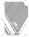
- Fig. 1 shows a catwalk 10 with two plank elements 11 which form the running surface of the catwalk 10 and which are laterally flanked by baseboards 12. Both the planks 11 and the baseboards 12 are profile elements, the cross-sectional shapes of Figs. 2 and 3 can be seen.
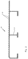
- planks 11 are approximately C-shaped in cross-section and have a reinforcing web 11.1 in the center. Their surface is provided with corrugations 11.2 to prevent slipping.
- Fig. 3 shows that the baseboards 12 are hollow profile elements which are provided on their outer surfaces with undercut grooves 13, 14, 15 and 16.
- the planks 11 are fastened by means of fastening angles 17 and screws 18 (FIG. 1), wherein the nuts not shown here are held to the screws 18 by the undercuts in the groove 13.
- FIG. 1 shows the Pressing direction of the profile of the plank 11 and the pressing direction of the profile of the baseboard 12 perpendicular to each other. This makes it possible in a simple way to produce walkways 10 different width.
- the planks 11 are simply cut to length.
- undercut grooves 14, 15 on the planks 11 facing side of the baseboards 12 are used for the attachment of stairs.
- the baseboards 12 then form the oblique lateral boundaries of the stairs.
- fastening means for anchoring the entire catwalk 10 can be accommodated on a machine console.
- this groove is also suitable for attachment of additional elements such as screens or the like.
- a relatively wide, rounded groove 17 is provided, can be hung in the brackets, not shown, for railing posts.
- the hollow profile element of the baseboard 12 could also be provided on the outer side with additional grooves, resulting in further mounting options for additional parts. All parts of the catwalk 10 can also be anodized because no welds are required to make it. If screw is used for mutual connection of the parts, the catwalk 10 is also easy to disassemble.
Landscapes
- Engineering & Computer Science (AREA)
- Architecture (AREA)
- Civil Engineering (AREA)
- Structural Engineering (AREA)
- Forms Removed On Construction Sites Or Auxiliary Members Thereof (AREA)
- Road Signs Or Road Markings (AREA)
- Devices Affording Protection Of Roads Or Walls For Sound Insulation (AREA)
- Connection Of Plates (AREA)
- Road Paving Structures (AREA)
- Bridges Or Land Bridges (AREA)
- Floor Finish (AREA)
- Mechanical Treatment Of Semiconductor (AREA)
- Glass Compositions (AREA)
- Control Of Motors That Do Not Use Commutators (AREA)
Description
- Die Erfindung betrifft einen Laufsteg, insbesondere zum Anbau an eine Maschinenanlage, mit mindestens einer Planke als Lauffläche, die mindestens an einer Außenseite mit einer als Hohlprofil ausgebildeten Fußleiste versehen ist.
- Solche Laufstege als Maschinenbegehungen aus Aluminium oder Edelstahl sind bereits bekannt. Die Fußleiste, die in der Regel nach oben über die Planke vorsteht, dient einerseits Sicherheitsaspekten, wie beispielsweise der Verhinderung des Herunterfallens von Gegenständen von den Planken oder des Abgleitens des Fußes einer Person von der Planke, falls sie auf dem Laufsteg ausrutscht, als auch der Befestigung des Laufstegs an einem Unterbau, beispielsweise der Konsole einer Maschinenanlage. Bei bekannten Laufstegen, wie sie auch von der Anmelderin selbst gefertigt werden, sind die Fußleisten als Winkelprofile ausgebildet, die mit der oder den Planken verschweißt werden und mittels derer der gesamte Laufsteg an einer Maschinenkonsole befestigbar ist. Die Planken und die Fußleisten sind somit die tragenden Teile des Laufstegs. Schweißverbindungen an tragenden Teilen stellen stets ein Sicherheitsrisiko dar, da es äußerst schwierig ist, qualitativ hochwertige Schweißungen herzustellen und deren Qualität anschließend zu kontrollieren. Aufgrund der Schweißverbindungen zwischen Planken und Fußleisten ist außerdem ein Voreloxieren der Teile nicht möglich, da die Eloxierung durch die Verschweißung im Bereich der Schweißnähte wieder zerstört würde. Schweißverbindungen haben außerdem den Nachteil, dass sie unlösbar sind, sodass eine Demontage des Laufstegs nur äußerst schwierig möglich ist.
- Aus der US 5,775,463 ist ein Laufsteg bekannt, der eine Planke und eine Fußleiste aufweist. Die Fußleiste weist eine seitliche Nut ohne Hinterschneidung auf, die einen Plankenrand aufnimmt. Weiterhin weist die Fußleiste eine Nut mit Hinterschneidung auf, die zur Aufnahme eines Abstandshalters bestimmt ist. Es ist vorgesehen, dass die Planke und die Fußleiste an einer Stelle durch Schweißen verbunden werden. Weiterhin ist offenbart, dass die Planke und die Fußleiste über Schrauben verbunden werden können.
- Der vorliegenden Erfindung liegt die Aufgabe zugrunde, einen Laufsteg zu schaffen, der die genannten Nachteile vermeidet.
- Die Aufgabe wird mit einem Laufsteg mit den Merkmalen des Anspruchs 1 gelöst.
- Die Ausgestaltung der Fußleiste als Hohlprofil erhöht die Stabilität der Fußleiste als tragendes Element. In der oder den Nuten an der Außenfläche können die Planken mittels Befestigungsmitteln, beispielsweise Schrauben, lösbar verankert werden, wodurch Schweißnähte und die damit verbundenen Sicherheitsprobleme vermieden werden. Außerdem erlaubt die lösbare Verbindung von Fußleiste und Planke eine relativ einfache Demontage des Laufstegs.
- Bei einer besonders vorteilhaften Ausführungsform kann die Fußleiste an ihrer der oder den Planken zugewandten Seite mit mindestens zwei parallelen Längsnuten versehen sein, in denen Befestigungsmittel zur Verankerung von Treppenstufen aufnehmbar sind. Die Fußleiste bildet dann die entsprechend der Steigung der Treppe verlaufende seitliche Berandung der Treppenstufen. Durch die beabstandete Anordnung von mindestens zwei Nuten können die Treppenstufen ebenfalls mittels Befestigungsmitteln, beispielsweise Schrauben, an der Fußleiste befestigt werden. Die Fußleiste ist somit auch bei Treppen ohne die Herstellung von Schweißnähten einsetzbar.
- Die Fußleiste kann außerdem an ihrer unteren Schmalseite mit einer hinterschnittenen Nut zur Aufnahme von Befestigungsmitteln zur Verankerung der Fußleiste an einer Konsole einer Maschinenanlage und/oder zur Befestigung einer Blende oder weiterer Zubehörteile versehen sein. Der Laufsteg wird somit insgesamt ebenfalls mit einer lösbaren Verbindung an der Maschine befestigt. Weitere Zubehörteile wie Blenden können ebenfalls in der Nut auf der Unterseite befestigt werden. Solche Blenden können beispielsweise Beschriftungen tragen.
- Weiterhin ist es möglich, die Fußleiste an ihrer oberen Schmalseite mit einer Nut zum Einhängen von Halterungen für Geländerpfosten zu versehen. Damit lässt sich also auch das Geländer unmittelbar mit dem Laufsteg verbinden und benötigt keine weitere Befestigung an der Maschine oder einem anderen Unterbau.
- Es ist außerdem von Vorteil, wenn die Fußleiste ein stranggepresstes Hohlprofil und die mindestens eine Planke ebenfalls ein Profilkörper ist, wobei die Pressrichtungen von Fußleiste und Planke im aneinander montierten Zustand senkrecht zueinander stehen. Diese Art der Ausgestaltung der Laufstege ermöglicht, verschieden breite Stege herzustellen, wobei die Breite stufenlos variiert werden kann. Die Profilkörper der Planken werden einfach entsprechend abgelängt.
- Der Laufsteg kann in an sich bekannter Weise aus Aluminium oder Edelstahl gefertigt sein. Durch den vollständigen Verzicht auf Schweißnähte können die Teile, insbesondere die Planken und die Fußleisten voreloxiert werden.
- Nachfolgend wird ein bevorzugtes Ausführungsbeispiel eines erfindungsgemäßen Laufstegs anhand der Zeichnung näher beschrieben.
- Es zeigen:
- Fig. 1
- eine teilweise aufgerissene perspektivische Ansicht von Planken eines erfindungsgemäßen Laufstegs mit seitlichen Fußleisten;
- Fig. 2
- einen Querschnitt durch eine Planke des Laufstegs aus Fig. 1,
- Fig. 3
- einen Querschnitt durch eine Fußleiste des Laufstegs aus Fig. 1.
- Fig. 1 zeigt einen Laufsteg 10 mit zwei Plankenelementen 11, die die Lauffläche des Laufstegs 10 bilden und die seitlich von Fußleisten 12 flankiert sind. Sowohl die Planken 11 als auch die Fußleisten 12 sind Profilelemente, deren Querschnittsformen aus den Fig. 2 und 3 ersichtlich sind.
- Wie Fig. 2 zeigt, sind die Planken 11 im Querschnitt ungefähr C-förmig und haben in der Mitte einen Verstärkungssteg 11.1. Ihre Oberfläche ist mit Riffelungen 11.2 versehen, die ein Ausgleiten verhindern sollen.
- Fig. 3 zeigt, dass die Fußleisten 12 Hohlprofilelemente sind, die an ihren Außenflächen mit hinterschnittenen Nuten 13, 14, 15 und 16 versehen sind. In der unteren Nut 13 werden die Planken 11 mittels Befestigungswinkeln 17 und Schrauben 18 (Fig. 1) befestigt, wobei die hier nicht ersichtlichen Muttern zu den Schrauben 18 durch die Hinterschneidungen in der Nut 13 gehalten werden. Bei dieser Art der Befestigung verläuft die Pressrichtung des Profils der Planke 11 und die Pressrichtung des Profils der Fußleiste 12 senkrecht zueinander. Dadurch ist es auf einfache Weise möglich, Laufstege 10 unterschiedlicher Breite herzustellen. Die Planken 11 werden einfach entsprechend abgelängt.
- Die weiteren, aus Fig. 3 ersichtlichen hinterschnittenen Nuten 14, 15 auf der den Planken 11 zugewandten Seite der Fußleisten 12 dienen der Befestigung von Treppenstufen. Die Fußleisten 12 bilden dann die schräg verlaufenden seitlichen Begrenzungen der Treppe.
- In der Nut 16 auf der unteren Schmalseite der Fußleiste 12 können Befestigungsmittel zur Verankerung des gesamten Laufstegs 10 an einer Maschinenkonsole aufgenommen werden. Außerdem eignet sich diese Nut auch zur Befestigung von zusätzlichen Elementen wie Blenden oder dergleichen.
- An der oberen Schmalseite der Fußleiste 12 ist eine relativ breite, abgerundete Nut 17 vorgesehen, in die nicht dargestellte Halterungen für Geländerpfosten eingehängt werden können.
- Selbstverständlich könnte das Hohlprofilelement der Fußleiste 12 auch auf der äußeren Seite mit zusätzlichen Nuten versehen sein, wodurch sich weitere Befestigungsmöglichkeiten für Zusatzteile ergeben. Alle Teile des Laufstegs 10 können außerdem voreloxiert werden, da keinerlei Schweißnähte zu seiner Herstellung erforderlich sind. Werden Schraubverbindungen zur gegenseitigen Verbindung der Teile eingesetzt, ist der Laufsteg 10 außerdem leicht demontierbar.
Claims (8)
- Laufsteg, insbesondere zum Anbau an eine Maschinenanlage, mit mindestens einer Planke (11) als Lauffläche, die mindestens an einer Außenseite mit einer als Hohlprofil ausgebildeten Fußleiste (12) versehen ist, dadurch gekennzeichnet, dass die Fußleiste (12) eine oder mehrere an mindestens einer Außenfläche eingearbeitete mit Hinterschneidungen versehene Befestigungsmittelaufnahmenuten (13, 14, 15, 16) zur Aufnahme von Befestigungsmitteln (18) aufweist und mit der oder den Planken (11) mittels in den Nuten (13, 14, 15, 16) verankerbaren Befestigungsmitteln (18) lösbar verbindbar ist.
- Laufsteg nach Anspruch 1, dadurch gekennzeichnet, dass die Fußleiste (12) an ihrer der oder den Planken (11) zugewandten Seite mit mindestens zwei parallelen Längsnuten (13, 14, 15) versehen ist, in denen Befestigungsmittel (18) zur Verankerung von Treppenstufen aufnehmbar sind.
- Laufsteg nach Anspruch 1 oder 2, dadurch gekennzeichnet, dass die Fußleiste (12) an ihrer unteren Schmalseite mit einer hinterschnittenen Nut (16) zur Verankerung der Fußleiste (12) an einer Konsole einer Maschinenanlage und/oder zur Befestigung einer Blende oder weiterer Zusatzteile versehen ist.
- Laufsteg nach einem der Ansprüche 1 bis 3, dadurch gekennzeichnet, dass die Fußleiste (12) an ihrer oberen Schmalseite mit einer Nut (19) zum Einhängen von Halterungen für Geländerpfosten versehen ist.
- Laufsteg nach einem der Ansprüche 1 bis 4, dadurch gekennzeichnet, dass die Fußleiste (12) ein stranggepresstes Hohlprofil und die mindestens eine Planke (11) ebenfalls ein Profilkörper ist, wobei die Pressrichtungen von Fußleiste (12) und Planke (11) im aneinander montierten Zustand senkrecht zueinander stehen.
- Laufsteg nach einem der Ansprüche 1 bis 5, dadurch gekennzeichnet, dass er aus Aluminium oder Edelstahl gefertigt ist.
- Laufsteg nach einem der Ansprüche 1 bis 6, dadurch gekennzeichnet, dass die Planken (11) und die Fußleisten (12) voreloxiert sind.
- Laufsteg nach einem der Ansprüche 1 bis 7, dadurch gekennzeichnet, dass die Befestigungsmittel Schrauben (18) mit Muttern sind.
Applications Claiming Priority (2)
| Application Number | Priority Date | Filing Date | Title |
|---|---|---|---|
| DE20207902U | 2002-05-22 | ||
| DE20207902U DE20207902U1 (de) | 2002-05-22 | 2002-05-22 | Laufsteg |
Publications (2)
| Publication Number | Publication Date |
|---|---|
| EP1365085A1 EP1365085A1 (de) | 2003-11-26 |
| EP1365085B1 true EP1365085B1 (de) | 2006-07-05 |
Family
ID=7971356
Family Applications (1)
| Application Number | Title | Priority Date | Filing Date |
|---|---|---|---|
| EP03011608A Expired - Lifetime EP1365085B1 (de) | 2002-05-22 | 2003-05-22 | Laufsteg |
Country Status (4)
| Country | Link |
|---|---|
| EP (1) | EP1365085B1 (de) |
| AT (1) | ATE332425T1 (de) |
| DE (2) | DE20207902U1 (de) |
| ES (1) | ES2265536T3 (de) |
Families Citing this family (1)
| Publication number | Priority date | Publication date | Assignee | Title |
|---|---|---|---|---|
| DE102019110932A1 (de) * | 2019-04-29 | 2020-10-29 | Voith Patent Gmbh | Laufsteg |
Family Cites Families (3)
| Publication number | Priority date | Publication date | Assignee | Title |
|---|---|---|---|---|
| DE3822621A1 (de) * | 1988-07-04 | 1989-11-30 | Hydropac Friedhofstechnik Inh | Laufrostanordnung |
| CA2033136C (en) | 1990-12-24 | 1994-12-27 | Ronald Lubinski | Knock-down base for platforms |
| US5775463A (en) * | 1996-07-15 | 1998-07-07 | Alumax Extrusions, Inc. | Toeboard system for a deckplate |
-
2002
- 2002-05-22 DE DE20207902U patent/DE20207902U1/de not_active Expired - Lifetime
-
2003
- 2003-05-22 AT AT03011608T patent/ATE332425T1/de active
- 2003-05-22 DE DE50304120T patent/DE50304120D1/de not_active Expired - Lifetime
- 2003-05-22 ES ES03011608T patent/ES2265536T3/es not_active Expired - Lifetime
- 2003-05-22 EP EP03011608A patent/EP1365085B1/de not_active Expired - Lifetime
Also Published As
| Publication number | Publication date |
|---|---|
| DE20207902U1 (de) | 2002-08-22 |
| DE50304120D1 (de) | 2006-08-17 |
| ES2265536T3 (es) | 2007-02-16 |
| ATE332425T1 (de) | 2006-07-15 |
| EP1365085A1 (de) | 2003-11-26 |
Similar Documents
| Publication | Publication Date | Title |
|---|---|---|
| EP2642045B1 (de) | Überlappungs-Anordnung von wenigstens zwei Laufplanken | |
| DE2916826C2 (de) | ||
| EP3137406B1 (de) | Fahrbahnsystem für eine fahrtreppe oder einen fahrsteig | |
| EP3034714B1 (de) | Spannvorrichtung zur aussteifung von hohlprofilen und verwendung derselben | |
| DE102008060212B3 (de) | Treppenmetallträger | |
| EP2295663A2 (de) | Verbindungsvorrichtung zwischen einem Decken- und Trennwandaufbau | |
| DE3821870A1 (de) | Schild, wegweiser oder verkehrszeichen | |
| EP1365085A1 (de) | Laufsteg | |
| EP4102007A1 (de) | Oberseitige begehungsmöglichkeit für ein wetterschutzdach | |
| EP2275625B1 (de) | Gerüstkonstruktion für ein Hauptgerüst und zweites Gerüst, insbesondere Podestgerüsttreppe | |
| DE10305145B4 (de) | Gerüsttreppenmodul | |
| DE69720692T2 (de) | Zustiegsvorrichtung | |
| EP2949834A1 (de) | Befestigungskonsole für Gerüstbretter, Gerüstbrett und Gerüst | |
| EP0268197A2 (de) | Gerüst, insbesondere Baugerüst | |
| DE19811750A1 (de) | Geländervorrichtung | |
| EP1347116B1 (de) | Profilelement mit einer Schiene und einer Hafte, Dachsystem und Verfahren zum Eindecken eines Daches | |
| EP0647748B1 (de) | Baugerüst aus Vertikalrahmen, Belagbohlen und Bordelementen | |
| DE4311788A1 (de) | Lauf- und Arbeitsflächen-Element | |
| DE9316247U1 (de) | Balkongeländer | |
| EP3733996B1 (de) | Laufsteg | |
| DE20200500U1 (de) | Anpassbare Treppe | |
| DE2401461B2 (de) | Befestigung von gelaenderholmen an gelaenderpfosten | |
| DE2231572A1 (de) | Montagetreppe | |
| DE202004013090U1 (de) | Gerüstmodul, insbesondere zum Anbau an eine Maschinenanlage | |
| DE1930677C (de) | An verschiedene Neigungen anpaßbare Treppe |
Legal Events
| Date | Code | Title | Description |
|---|---|---|---|
| PUAI | Public reference made under article 153(3) epc to a published international application that has entered the european phase |
Free format text: ORIGINAL CODE: 0009012 |
|
| AK | Designated contracting states |
Kind code of ref document: A1 Designated state(s): AT BE BG CH CY CZ DE DK EE ES FI FR GB GR HU IE IT LI LU MC NL PT RO SE SI SK TR |
|
| AX | Request for extension of the european patent |
Extension state: AL LT LV MK |
|
| 17P | Request for examination filed |
Effective date: 20040515 |
|
| AKX | Designation fees paid |
Designated state(s): AT BE BG CH CY CZ DE DK EE ES FI FR GB GR HU IE IT LI LU MC NL PT RO SE SI SK TR |
|
| 17Q | First examination report despatched |
Effective date: 20050318 |
|
| GRAP | Despatch of communication of intention to grant a patent |
Free format text: ORIGINAL CODE: EPIDOSNIGR1 |
|
| GRAS | Grant fee paid |
Free format text: ORIGINAL CODE: EPIDOSNIGR3 |
|
| GRAA | (expected) grant |
Free format text: ORIGINAL CODE: 0009210 |
|
| AK | Designated contracting states |
Kind code of ref document: B1 Designated state(s): AT BE BG CH CY CZ DE DK EE ES FI FR GB GR HU IE IT LI LU MC NL PT RO SE SI SK TR |
|
| PG25 | Lapsed in a contracting state [announced via postgrant information from national office to epo] |
Ref country code: SK Free format text: LAPSE BECAUSE OF FAILURE TO SUBMIT A TRANSLATION OF THE DESCRIPTION OR TO PAY THE FEE WITHIN THE PRESCRIBED TIME-LIMIT Effective date: 20060705 Ref country code: IT Free format text: LAPSE BECAUSE OF FAILURE TO SUBMIT A TRANSLATION OF THE DESCRIPTION OR TO PAY THE FEE WITHIN THE PRESCRIBED TIME-LIMIT;WARNING: LAPSES OF ITALIAN PATENTS WITH EFFECTIVE DATE BEFORE 2007 MAY HAVE OCCURRED AT ANY TIME BEFORE 2007. THE CORRECT EFFECTIVE DATE MAY BE DIFFERENT FROM THE ONE RECORDED. Effective date: 20060705 Ref country code: RO Free format text: LAPSE BECAUSE OF FAILURE TO SUBMIT A TRANSLATION OF THE DESCRIPTION OR TO PAY THE FEE WITHIN THE PRESCRIBED TIME-LIMIT Effective date: 20060705 Ref country code: SI Free format text: LAPSE BECAUSE OF FAILURE TO SUBMIT A TRANSLATION OF THE DESCRIPTION OR TO PAY THE FEE WITHIN THE PRESCRIBED TIME-LIMIT Effective date: 20060705 Ref country code: NL Free format text: LAPSE BECAUSE OF FAILURE TO SUBMIT A TRANSLATION OF THE DESCRIPTION OR TO PAY THE FEE WITHIN THE PRESCRIBED TIME-LIMIT Effective date: 20060705 Ref country code: IE Free format text: LAPSE BECAUSE OF FAILURE TO SUBMIT A TRANSLATION OF THE DESCRIPTION OR TO PAY THE FEE WITHIN THE PRESCRIBED TIME-LIMIT Effective date: 20060705 Ref country code: CZ Free format text: LAPSE BECAUSE OF FAILURE TO SUBMIT A TRANSLATION OF THE DESCRIPTION OR TO PAY THE FEE WITHIN THE PRESCRIBED TIME-LIMIT Effective date: 20060705 Ref country code: GB Free format text: LAPSE BECAUSE OF FAILURE TO SUBMIT A TRANSLATION OF THE DESCRIPTION OR TO PAY THE FEE WITHIN THE PRESCRIBED TIME-LIMIT Effective date: 20060705 |
|
| REG | Reference to a national code |
Ref country code: GB Ref legal event code: FG4D Free format text: NOT ENGLISH |
|
| REG | Reference to a national code |
Ref country code: CH Ref legal event code: EP |
|
| REG | Reference to a national code |
Ref country code: CH Ref legal event code: NV Representative=s name: ROTTMANN, ZIMMERMANN + PARTNER AG |
|
| REG | Reference to a national code |
Ref country code: IE Ref legal event code: FG4D Free format text: LANGUAGE OF EP DOCUMENT: GERMAN |
|
| REF | Corresponds to: |
Ref document number: 50304120 Country of ref document: DE Date of ref document: 20060817 Kind code of ref document: P |
|
| PG25 | Lapsed in a contracting state [announced via postgrant information from national office to epo] |
Ref country code: BG Free format text: LAPSE BECAUSE OF FAILURE TO SUBMIT A TRANSLATION OF THE DESCRIPTION OR TO PAY THE FEE WITHIN THE PRESCRIBED TIME-LIMIT Effective date: 20061005 Ref country code: DK Free format text: LAPSE BECAUSE OF FAILURE TO SUBMIT A TRANSLATION OF THE DESCRIPTION OR TO PAY THE FEE WITHIN THE PRESCRIBED TIME-LIMIT Effective date: 20061005 |
|
| REG | Reference to a national code |
Ref country code: SE Ref legal event code: TRGR |
|
| NLV1 | Nl: lapsed or annulled due to failure to fulfill the requirements of art. 29p and 29m of the patents act | ||
| PG25 | Lapsed in a contracting state [announced via postgrant information from national office to epo] |
Ref country code: PT Free format text: LAPSE BECAUSE OF FAILURE TO SUBMIT A TRANSLATION OF THE DESCRIPTION OR TO PAY THE FEE WITHIN THE PRESCRIBED TIME-LIMIT Effective date: 20061205 |
|
| GBV | Gb: ep patent (uk) treated as always having been void in accordance with gb section 77(7)/1977 [no translation filed] |
Effective date: 20060705 |
|
| ET | Fr: translation filed | ||
| REG | Reference to a national code |
Ref country code: ES Ref legal event code: FG2A Ref document number: 2265536 Country of ref document: ES Kind code of ref document: T3 |
|
| REG | Reference to a national code |
Ref country code: IE Ref legal event code: FD4D |
|
| PLBE | No opposition filed within time limit |
Free format text: ORIGINAL CODE: 0009261 |
|
| STAA | Information on the status of an ep patent application or granted ep patent |
Free format text: STATUS: NO OPPOSITION FILED WITHIN TIME LIMIT |
|
| 26N | No opposition filed |
Effective date: 20070410 |
|
| BERE | Be: lapsed |
Owner name: KRAMER G.M.B.H. Effective date: 20070531 |
|
| PG25 | Lapsed in a contracting state [announced via postgrant information from national office to epo] |
Ref country code: MC Free format text: LAPSE BECAUSE OF NON-PAYMENT OF DUE FEES Effective date: 20070531 |
|
| PG25 | Lapsed in a contracting state [announced via postgrant information from national office to epo] |
Ref country code: BE Free format text: LAPSE BECAUSE OF NON-PAYMENT OF DUE FEES Effective date: 20070531 |
|
| PG25 | Lapsed in a contracting state [announced via postgrant information from national office to epo] |
Ref country code: GR Free format text: LAPSE BECAUSE OF FAILURE TO SUBMIT A TRANSLATION OF THE DESCRIPTION OR TO PAY THE FEE WITHIN THE PRESCRIBED TIME-LIMIT Effective date: 20061006 |
|
| PG25 | Lapsed in a contracting state [announced via postgrant information from national office to epo] |
Ref country code: EE Free format text: LAPSE BECAUSE OF FAILURE TO SUBMIT A TRANSLATION OF THE DESCRIPTION OR TO PAY THE FEE WITHIN THE PRESCRIBED TIME-LIMIT Effective date: 20060705 |
|
| PG25 | Lapsed in a contracting state [announced via postgrant information from national office to epo] |
Ref country code: CY Free format text: LAPSE BECAUSE OF FAILURE TO SUBMIT A TRANSLATION OF THE DESCRIPTION OR TO PAY THE FEE WITHIN THE PRESCRIBED TIME-LIMIT Effective date: 20060705 Ref country code: LU Free format text: LAPSE BECAUSE OF NON-PAYMENT OF DUE FEES Effective date: 20070522 |
|
| PG25 | Lapsed in a contracting state [announced via postgrant information from national office to epo] |
Ref country code: TR Free format text: LAPSE BECAUSE OF FAILURE TO SUBMIT A TRANSLATION OF THE DESCRIPTION OR TO PAY THE FEE WITHIN THE PRESCRIBED TIME-LIMIT Effective date: 20060705 Ref country code: HU Free format text: LAPSE BECAUSE OF FAILURE TO SUBMIT A TRANSLATION OF THE DESCRIPTION OR TO PAY THE FEE WITHIN THE PRESCRIBED TIME-LIMIT Effective date: 20070106 |
|
| REG | Reference to a national code |
Ref country code: CH Ref legal event code: PFA Owner name: KRAEMER GMBH Free format text: KRAEMER GMBH#HEINRICH-HEINE-STRASSE 32#72555 METZINGEN (DE) -TRANSFER TO- KRAEMER GMBH#HEINRICH-HEINE-STRASSE 32#72555 METZINGEN (DE) |
|
| REG | Reference to a national code |
Ref country code: FR Ref legal event code: PLFP Year of fee payment: 13 |
|
| REG | Reference to a national code |
Ref country code: FR Ref legal event code: PLFP Year of fee payment: 14 |
|
| REG | Reference to a national code |
Ref country code: CH Ref legal event code: PCAR Free format text: NEW ADDRESS: GARTENSTRASSE 28 A, 5400 BADEN (CH) |
|
| REG | Reference to a national code |
Ref country code: FR Ref legal event code: PLFP Year of fee payment: 15 |
|
| REG | Reference to a national code |
Ref country code: FR Ref legal event code: PLFP Year of fee payment: 16 |
|
| PGFP | Annual fee paid to national office [announced via postgrant information from national office to epo] |
Ref country code: SE Payment date: 20220523 Year of fee payment: 20 Ref country code: IT Payment date: 20220531 Year of fee payment: 20 Ref country code: FR Payment date: 20220523 Year of fee payment: 20 Ref country code: ES Payment date: 20220617 Year of fee payment: 20 Ref country code: DE Payment date: 20220518 Year of fee payment: 20 |
|
| PGFP | Annual fee paid to national office [announced via postgrant information from national office to epo] |
Ref country code: FI Payment date: 20220517 Year of fee payment: 20 Ref country code: CH Payment date: 20220523 Year of fee payment: 20 Ref country code: AT Payment date: 20220517 Year of fee payment: 20 |
|
| REG | Reference to a national code |
Ref country code: DE Ref legal event code: R071 Ref document number: 50304120 Country of ref document: DE |
|
| REG | Reference to a national code |
Ref country code: ES Ref legal event code: FD2A Effective date: 20230529 |
|
| REG | Reference to a national code |
Ref country code: CH Ref legal event code: PL |
|
| REG | Reference to a national code |
Ref country code: SE Ref legal event code: EUG |
|
| REG | Reference to a national code |
Ref country code: AT Ref legal event code: MK07 Ref document number: 332425 Country of ref document: AT Kind code of ref document: T Effective date: 20230522 |
|
| PG25 | Lapsed in a contracting state [announced via postgrant information from national office to epo] |
Ref country code: ES Free format text: LAPSE BECAUSE OF EXPIRATION OF PROTECTION Effective date: 20230523 |