EP1365131A2 - Procédé de reglage d'un catalyseur d'accumulation de NOx - Google Patents
Procédé de reglage d'un catalyseur d'accumulation de NOx Download PDFInfo
- Publication number
- EP1365131A2 EP1365131A2 EP03090075A EP03090075A EP1365131A2 EP 1365131 A2 EP1365131 A2 EP 1365131A2 EP 03090075 A EP03090075 A EP 03090075A EP 03090075 A EP03090075 A EP 03090075A EP 1365131 A2 EP1365131 A2 EP 1365131A2
- Authority
- EP
- European Patent Office
- Prior art keywords
- catalytic converter
- regeneration
- storage catalytic
- storage
- xse
- Prior art date
- Legal status (The legal status is an assumption and is not a legal conclusion. Google has not performed a legal analysis and makes no representation as to the accuracy of the status listed.)
- Granted
Links
Images


Classifications
-
- F—MECHANICAL ENGINEERING; LIGHTING; HEATING; WEAPONS; BLASTING
- F02—COMBUSTION ENGINES; HOT-GAS OR COMBUSTION-PRODUCT ENGINE PLANTS
- F02D—CONTROLLING COMBUSTION ENGINES
- F02D41/00—Electrical control of supply of combustible mixture or its constituents
- F02D41/02—Circuit arrangements for generating control signals
- F02D41/14—Introducing closed-loop corrections
- F02D41/1438—Introducing closed-loop corrections using means for determining characteristics of the combustion gases; Sensors therefor
- F02D41/1444—Introducing closed-loop corrections using means for determining characteristics of the combustion gases; Sensors therefor characterised by the characteristics of the combustion gases
- F02D41/146—Introducing closed-loop corrections using means for determining characteristics of the combustion gases; Sensors therefor characterised by the characteristics of the combustion gases the characteristics being an NOx content or concentration
-
- F—MECHANICAL ENGINEERING; LIGHTING; HEATING; WEAPONS; BLASTING
- F01—MACHINES OR ENGINES IN GENERAL; ENGINE PLANTS IN GENERAL; STEAM ENGINES
- F01N—GAS-FLOW SILENCERS OR EXHAUST APPARATUS FOR MACHINES OR ENGINES IN GENERAL; GAS-FLOW SILENCERS OR EXHAUST APPARATUS FOR INTERNAL-COMBUSTION ENGINES
- F01N13/00—Exhaust or silencing apparatus characterised by constructional features
- F01N13/009—Exhaust or silencing apparatus characterised by constructional features having two or more separate purifying devices arranged in series
-
- F—MECHANICAL ENGINEERING; LIGHTING; HEATING; WEAPONS; BLASTING
- F02—COMBUSTION ENGINES; HOT-GAS OR COMBUSTION-PRODUCT ENGINE PLANTS
- F02D—CONTROLLING COMBUSTION ENGINES
- F02D41/00—Electrical control of supply of combustible mixture or its constituents
- F02D41/02—Circuit arrangements for generating control signals
- F02D41/021—Introducing corrections for particular conditions exterior to the engine
- F02D41/0235—Introducing corrections for particular conditions exterior to the engine in relation with the state of the exhaust gas treating apparatus
- F02D41/027—Introducing corrections for particular conditions exterior to the engine in relation with the state of the exhaust gas treating apparatus to purge or regenerate the exhaust gas treating apparatus
- F02D41/0275—Introducing corrections for particular conditions exterior to the engine in relation with the state of the exhaust gas treating apparatus to purge or regenerate the exhaust gas treating apparatus the exhaust gas treating apparatus being a NOx trap or adsorbent
-
- F—MECHANICAL ENGINEERING; LIGHTING; HEATING; WEAPONS; BLASTING
- F01—MACHINES OR ENGINES IN GENERAL; ENGINE PLANTS IN GENERAL; STEAM ENGINES
- F01N—GAS-FLOW SILENCERS OR EXHAUST APPARATUS FOR MACHINES OR ENGINES IN GENERAL; GAS-FLOW SILENCERS OR EXHAUST APPARATUS FOR INTERNAL-COMBUSTION ENGINES
- F01N2430/00—Influencing exhaust purification, e.g. starting of catalytic reaction, filter regeneration, or the like, by controlling engine operating characteristics
- F01N2430/06—Influencing exhaust purification, e.g. starting of catalytic reaction, filter regeneration, or the like, by controlling engine operating characteristics by varying fuel-air ratio, e.g. by enriching fuel-air mixture
-
- F—MECHANICAL ENGINEERING; LIGHTING; HEATING; WEAPONS; BLASTING
- F01—MACHINES OR ENGINES IN GENERAL; ENGINE PLANTS IN GENERAL; STEAM ENGINES
- F01N—GAS-FLOW SILENCERS OR EXHAUST APPARATUS FOR MACHINES OR ENGINES IN GENERAL; GAS-FLOW SILENCERS OR EXHAUST APPARATUS FOR INTERNAL-COMBUSTION ENGINES
- F01N2560/00—Exhaust systems with means for detecting or measuring exhaust gas components or characteristics
- F01N2560/02—Exhaust systems with means for detecting or measuring exhaust gas components or characteristics the means being an exhaust gas sensor
- F01N2560/026—Exhaust systems with means for detecting or measuring exhaust gas components or characteristics the means being an exhaust gas sensor for measuring or detecting NOx
-
- F—MECHANICAL ENGINEERING; LIGHTING; HEATING; WEAPONS; BLASTING
- F01—MACHINES OR ENGINES IN GENERAL; ENGINE PLANTS IN GENERAL; STEAM ENGINES
- F01N—GAS-FLOW SILENCERS OR EXHAUST APPARATUS FOR MACHINES OR ENGINES IN GENERAL; GAS-FLOW SILENCERS OR EXHAUST APPARATUS FOR INTERNAL-COMBUSTION ENGINES
- F01N3/00—Exhaust or silencing apparatus having means for purifying, rendering innocuous, or otherwise treating exhaust
- F01N3/08—Exhaust or silencing apparatus having means for purifying, rendering innocuous, or otherwise treating exhaust for rendering innocuous
- F01N3/0807—Exhaust or silencing apparatus having means for purifying, rendering innocuous, or otherwise treating exhaust for rendering innocuous by using absorbents or adsorbents
- F01N3/0828—Exhaust or silencing apparatus having means for purifying, rendering innocuous, or otherwise treating exhaust for rendering innocuous by using absorbents or adsorbents characterised by the absorbed or adsorbed substances
- F01N3/0842—Nitrogen oxides
-
- F—MECHANICAL ENGINEERING; LIGHTING; HEATING; WEAPONS; BLASTING
- F02—COMBUSTION ENGINES; HOT-GAS OR COMBUSTION-PRODUCT ENGINE PLANTS
- F02D—CONTROLLING COMBUSTION ENGINES
- F02D2200/00—Input parameters for engine control
- F02D2200/02—Input parameters for engine control the parameters being related to the engine
- F02D2200/08—Exhaust gas treatment apparatus parameters
- F02D2200/0802—Temperature of the exhaust gas treatment apparatus
-
- F—MECHANICAL ENGINEERING; LIGHTING; HEATING; WEAPONS; BLASTING
- F02—COMBUSTION ENGINES; HOT-GAS OR COMBUSTION-PRODUCT ENGINE PLANTS
- F02D—CONTROLLING COMBUSTION ENGINES
- F02D2200/00—Input parameters for engine control
- F02D2200/02—Input parameters for engine control the parameters being related to the engine
- F02D2200/08—Exhaust gas treatment apparatus parameters
- F02D2200/0814—Oxygen storage amount
Definitions
- the invention relates to a method for controlling a NO x storage catalytic converter with the features mentioned in the preamble of claim 1.
- the exhaust gas is passed over at least one catalytic converter, which converts one or more pollutant components of the exhaust gas.
- Catalytic converter which converts one or more pollutant components of the exhaust gas.
- Oxidation catalysts promote the oxidation of unburned hydrocarbons (HC) and carbon monoxide (CO), while reduction catalysts help reduce nitrogen oxides (NO x ) in the exhaust gas.
- 3-way catalysts are used to catalyze the conversion of the three aforementioned components (HC, CO, NO X ) at the same time.
- lean-burn internal combustion engines are used to optimize the consumption of motor vehicles.
- a fuel-efficient lean-burn operation in which the internal combustion engine is operated with an excess of oxygen, that is to say with ⁇ > 1, a complete 3-way catalytic conversion of NO x is not possible.
- NO x storage catalysts are used which, in addition to a catalytic component, contain a NO x storage which stores NO x in the form of nitrate in the lean operating phases.
- intermediate rich regeneration phases at ⁇ ⁇ 1 in which HC and CO are formed, which act as reducing agents, the nitrates are reduced to nitrogen N 2 .
- a catalyst for example a 3-way catalyst, is often connected upstream of the NO x storage catalyst.
- a regeneration period is predefined by means of a rich exhaust gas atmosphere.
- the actual loading state of the NO x storage catalytic converter and a current regeneration rate thereof cannot be taken into account disadvantageously.
- Such a procedure therefore harbors the risk that the regeneration period is too short or too long, in the first case an incomplete regeneration of the storage and in the second case an unnecessary increase in fuel consumption and an emission of environmentally harmful reducing agents (HC and CO) are accepted.
- Various methods are known for initiating the regeneration of the NO x storage catalytic converter, which are usually based on stored behavior models of the NO x storage catalytic converter or on emission profiles measured by means of a NO x sensor, for example. Particularly in the latter case it may be that the initiation of regeneration is exclusively demand performed at appropriate NOx breakthrough.
- the NO X regeneration is carried out in such a way that the regeneration is ended as soon as the signal from the downstream oxygen-sensitive sensor system has reached a certain threshold value or a behavior model for the catalytic converter has determined the time of its complete emptying. Both processes are usually designed so that there is only a small breakthrough of reducing agent at the end of regeneration. In exceptional cases, a small excess of reducing agent can be tolerated for various reasons.
- the invention is therefore based on the object of providing a method for controlling a NO x storage catalytic converter which is optimized with respect to the lowest possible reducing agent emissions compared to the prior art and which is too high saturation and thus poorer regenerability of the NO x Storage catalytic converter avoids.
- the first method step according to the invention which takes place at the beginning of a regeneration phase, ensures that the rich exhaust gases located at the end of a regeneration phase in front of the NO x storage catalytic converter, due to the determination of a combustion lambda, which takes into account the diffusion rate of the oxygen-containing components of the catalyst coating, optimally
- Regeneration of the NO x storage catalyst can be used, so that a reducing agent breakthrough is advantageously reduced.
- the engine operating point, the exhaust gas mass flow and / or the catalyst state which can be determined by known methods, for example by means of a conversion factor, can be used to determine the combustion lambda.
- the NO x signal of the NO x sensor and preferably no timing diagram is preferably used.
- this becomes Regeneration of air-fuel mixture (combustion lambda) not only at the beginning set during regeneration, but also varies during regeneration as the Conditions for determining the combustion lambda after the start of regeneration can be changeable. This variation can be carried out using known methods become.
- the two further method steps of the main claim which are carried out alternatively, avoid saturation of the NO x storage catalytic converter, or their effects are compensated for by inventive measures. Therefore, the NO x storage catalytic converter can usually be completely discharged during the regeneration phase.
- the predefined threshold value for the saturation state of the NO x storage catalytic converter is determined in advance by suitable tests. This provides information about the loading of the NO x storage catalytic converter with which the NO x regeneration with normal implementation still leads to an adequate conversion of all stored nitrogen oxides.
- the current value for the loading of the NO x storage catalytic converter is determined by balancing the NO x M constrictions before and after the NO x storage catalytic converter.
- the signal of the NO X- sensitive measuring device for example the signal of a second NO X- sensitive measuring device located in front of the NO X * storage catalytic converter or a corresponding modeling in the engine control unit can be used.
- the threshold value can additionally be dependent on further factors, for example catalyst / exhaust gas temperature, exhaust gas mass flow, NO x raw mass flow, HC content of the lean exhaust gas and the like, which may have to be taken into account as correction values for the threshold value.
- At least one next NO X regeneration can be extended explicitly.
- An increased breakthrough of reducing agents due to the more intensive regeneration is accepted.
- reaching the threshold value can be used for diagnosis of the catalyst or other evaluating the current storage capacity of the catalyst Deactivate functionalities in the following period.
- the withdrawal of this Deactivation can, for example, be made dependent on a certain cumulative Amount of reducing agent or a predetermined minimum number of Regenerative processes.
- the NO X -sensitive measuring device is a NOx sensor, which also provides an oxygen-dependent signal which can be used to monitor the regeration of the NO X storage catalytic converter.
- an additional oxygen-sensitive measuring device such as a lambda broadband or step probe can be used to monitor the regeneration phase.
- the internal combustion engine 10 shown in FIG. 1 is followed by an exhaust system 12.
- the exhaust system 12 has an exhaust duct 14, in which a pre-catalytic converter 16 arranged near the engine and a large-volume NO x storage catalytic converter 18 are located.
- the exhaust gas duct 14 usually has various gas and / or temperature sensors for regulating the internal combustion engine 10, but not shown here. 1 shows only one NO X sensor 20, which is arranged downstream of the NO X storage catalytic converter 18 and which supplies a signal U NOX for the proportion of NO X in the exhaust gas.
- the NO x sensor 20 is equipped with a lambda measurement function, so that a signal U ⁇ which is dependent on an oxygen component of the exhaust gas is additionally provided.
- the signals U NOX and U ⁇ are transmitted to an engine control unit 22, in which they are digitized and further processed. Further information relating to the operating state of the internal combustion engine 10 is also input into the engine control unit 22.
- a control unit 24 is also integrated in the engine control unit 22.
- the engine control unit 22 and the control unit 24 influence at least one operating parameter of the internal combustion engine 10, in particular an air / fuel mixture to be supplied (combustion lambda), as a function of the signals U NOX and U ⁇ of the NO X sensor 20.
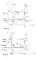
- FIG. 2 shows the course over time of various parameters of the internal combustion engine 10 and of the exhaust system 12 during a NO x regeneration of the NO x storage catalytic converter 18, which takes place according to the prior art.
- the internal combustion engine 10 is in a lean operating mode, in which an oxygen-rich air-fuel mixture with ⁇ M »1 is fed to it (graph 100).
- the exhaust gas contains an excess of nitrogen oxides NO x , which cannot be completely converted by the pre-catalyst 16.
- NO X is therefore stored in the NO X storage catalytic converter 18, the NO X loading of which increases continuously until the NO XMAX saturation (graph 102).
- a suitable criterion a need for NO x regeneration is recognized at a time t A.
- the internal combustion engine 10 is switched by influencing the engine control unit 22 in a rich operating mode with ⁇ F ⁇ 1.
- the stored in the NO X storing catalyst 18 NO X is desorbed and reduced to nitrogen.
- a decrease in the NO x loading of the storage catalytic converter 18 can only be recorded after a certain time delay after switching over the internal combustion engine 10, since at the point in time t A the exhaust gas duct 14 is still filled with lean exhaust gas, which initially still contains the storage catalytic converter 18 must happen before the reducing agents reach it.
- the course of the NO x regeneration is followed in the meantime with the aid of the signal U ⁇ provided by the NO x sensor 20.
- the signal U ⁇ (graph 104) is inversely proportional to an oxygen concentration of the exhaust gas downstream of the storage catalytic converter 18. As the reducing agents are consumed to an ever smaller extent as regeneration progresses, the signal U ⁇ of the NO x sensor 20 rises slowly. At a time t E , the signal U ⁇ reaches a predetermined threshold value U SE , whereupon the internal combustion engine 10 is usually switched back to a lean operating mode with ⁇ M »1.
- FIG. 3 In order to prevent the saturation of the NO x storage catalytic converter and the associated incomplete outsourcing of the nitrates in the regeneration phase, the approach shown in FIG. 3 is followed according to the invention, the course over time of the same parameters as in FIG. 2 and additionally the course of the signal U NOX (graph 108) of the NO x sensor 20 for the NO x emission is shown.
- the NO x emission rises steeply with increasing loading of the NO x storage catalytic converter 18, at the time t A when a predetermined threshold value NO XSE is reached , which is determined by balancing the amounts of NO x before and after the NO x storage catalytic converter 18 and which is related to the saturation of the NO x storage catalytic converter 18, the regeneration of the NO x storage catalytic converter 18 is initiated.
- the threshold value NO XSE is determined experimentally in advance and indicates the point in the NO X storage loading at which a complete emptying of the NO X storage catalytic converter is still possible in a subsequent regeneration phase . After initiation of regeneration, the NO X emission drops sharply and remains at a constantly low level.
- the course of the NO x loading of the NO x storage catalytic converter 18 - represented by graph 102 - essentially corresponds to the course according to FIG. 2, since the loading and the emptying are subject to the same mechanisms. However, the graph 102 is at a lower level since the emptying begins at a lower loading state and only ends when the emptying is complete.
- the temperature of the storage catalytic converter 18 is determined at time t A and transmitted to the engine control unit 22, which then the internal combustion engine 10 is switched from a lean operating mode with ⁇ M »1 to a rich mode with ⁇ F ⁇ 1, the determined catalyst temperature being used to determine an optimized combustion lambda.
- a combustion lambda ⁇ F is set, which can be higher ( ⁇ FT1 ), lower ( ⁇ FT2 ) or equal to the combustion lambda ⁇ FT0 , which can be carried out without evaluating the temperature of the NO x Storage catalyst 18 would have been set.
- the setting of a combustion lambda ⁇ F which takes into account at least the temperature of the NO x storage catalytic converter 18 as a decisive factor, ensures that the rich exhaust gases at the time t E at the end of a regeneration phase before the NO x storage catalytic converter 18 still have to be regenerated of the NO x storage catalyst 18 can be used. A breakthrough of reducing agents can thus be significantly reduced.
Landscapes
- Engineering & Computer Science (AREA)
- Chemical & Material Sciences (AREA)
- Combustion & Propulsion (AREA)
- Mechanical Engineering (AREA)
- General Engineering & Computer Science (AREA)
- Exhaust Gas After Treatment (AREA)
- Electrical Control Of Air Or Fuel Supplied To Internal-Combustion Engine (AREA)
- Catalysts (AREA)
- Exhaust Gas Treatment By Means Of Catalyst (AREA)
Applications Claiming Priority (2)
| Application Number | Priority Date | Filing Date | Title |
|---|---|---|---|
| DE10221568 | 2002-05-08 | ||
| DE10221568A DE10221568A1 (de) | 2002-05-08 | 2002-05-08 | Verfahren zur Steuerung eines NO¶x¶-Speicherkatalysators |
Publications (3)
| Publication Number | Publication Date |
|---|---|
| EP1365131A2 true EP1365131A2 (fr) | 2003-11-26 |
| EP1365131A3 EP1365131A3 (fr) | 2004-04-07 |
| EP1365131B1 EP1365131B1 (fr) | 2006-08-16 |
Family
ID=29285423
Family Applications (1)
| Application Number | Title | Priority Date | Filing Date |
|---|---|---|---|
| EP03090075A Expired - Lifetime EP1365131B1 (fr) | 2002-05-08 | 2003-03-20 | Procédé de reglage d'un catalyseur d'accumulation de NOx |
Country Status (3)
| Country | Link |
|---|---|
| EP (1) | EP1365131B1 (fr) |
| AT (1) | ATE336650T1 (fr) |
| DE (2) | DE10221568A1 (fr) |
Cited By (1)
| Publication number | Priority date | Publication date | Assignee | Title |
|---|---|---|---|---|
| DE10360072A1 (de) * | 2003-12-20 | 2005-07-14 | Audi Ag | Abgasanlage für eine Brennkraftmaschine eines Fahrzeuges, insbesondere eines Kraftfahrzeuges |
Families Citing this family (1)
| Publication number | Priority date | Publication date | Assignee | Title |
|---|---|---|---|---|
| DE102004022814B4 (de) * | 2004-05-08 | 2010-06-10 | Audi Ag | Verfahren zum Betreiben einer magerlauffähigen Brennkraftmaschine eines Fahrzeuges, insbesondere eines Kraftfahrzeuges |
Family Cites Families (4)
| Publication number | Priority date | Publication date | Assignee | Title |
|---|---|---|---|---|
| DE59800195D1 (de) * | 1998-01-09 | 2000-08-17 | Ford Global Tech Inc | Verfahren zur Regeneration einer Stickoxidfalle im Abgassystem eines Verbrennungsmotors |
| DE19851564C2 (de) * | 1998-11-09 | 2000-08-24 | Siemens Ag | Verfahren zum Betreiben und Überprüfen eines NOx-Speicherreduktionskatalysators einer Mager-Brennkraftmaschine |
| DE19929292A1 (de) * | 1999-06-25 | 2000-12-28 | Volkswagen Ag | Verfahren zur Steuerung eines Arbeitsmodus einer Verbrennungskraftmaschine |
| DE19933712A1 (de) * | 1999-07-19 | 2001-05-17 | Volkswagen Ag | Verfahren zur Regelung eines Arbeitsmodus einer Verbrennungskraftmaschine |
-
2002
- 2002-05-08 DE DE10221568A patent/DE10221568A1/de not_active Withdrawn
-
2003
- 2003-03-20 EP EP03090075A patent/EP1365131B1/fr not_active Expired - Lifetime
- 2003-03-20 AT AT03090075T patent/ATE336650T1/de not_active IP Right Cessation
- 2003-03-20 DE DE50304630T patent/DE50304630D1/de not_active Expired - Lifetime
Cited By (1)
| Publication number | Priority date | Publication date | Assignee | Title |
|---|---|---|---|---|
| DE10360072A1 (de) * | 2003-12-20 | 2005-07-14 | Audi Ag | Abgasanlage für eine Brennkraftmaschine eines Fahrzeuges, insbesondere eines Kraftfahrzeuges |
Also Published As
| Publication number | Publication date |
|---|---|
| DE10221568A1 (de) | 2003-12-04 |
| ATE336650T1 (de) | 2006-09-15 |
| DE50304630D1 (de) | 2006-09-28 |
| EP1365131A3 (fr) | 2004-04-07 |
| EP1365131B1 (fr) | 2006-08-16 |
Similar Documents
| Publication | Publication Date | Title |
|---|---|---|
| EP1214511B1 (fr) | PROCEDE POUR SURVEILLER LE FONCTIONNEMENT D'UN DETECTEUR DE NOx PLACE DANS LA CONDUITE DES GAZ D'ECHAPPEMENT D'UN MOTEUR A COMBUSTION INTERNE | |
| DE19801625A1 (de) | Diagnose eines NOx-Speicherkatalysators beim Betrieb von Verbrennungsmotoren | |
| DE10226187B4 (de) | Verfahren und Vorrichtung zur Quantifizierung von in einer Emissionsbegrenzungseinrichtung gespeichertem Sauerstoff | |
| DE19961165A1 (de) | Verfahren zur Entschwefelung eines in einem Abgaskanal einer Verbrennungskraftmaschine angeordneten NO¶x¶-Speicherkatalysators | |
| EP1311748B1 (fr) | Procede et modele de modelisation d'une phase d'extraction d'un pot catalytique a accumulation d'oxyde d'azote | |
| DE102009046433A1 (de) | Verfahren und Vorrichtung zur Überwachung einer Abgasreinigungsanlage | |
| DE10003219A1 (de) | Verfahren und Vorrichtung zur Regelung eines in einem Abgaskanal einer Verbrennungskraftmaschine angeordneten NOx-Speicherkatalysators | |
| EP1192343B1 (fr) | PROCEDE PERMETTANT DE LANCER ET DE SURVEILLER LA DESULFURATION D'AU MOINS UN CATALYSEUR A STOCKAGE DE NOx PLACE DANS UN TUYAU D'ECHAPPEMENT D'UN MOTEUR A COMBUSTION INTERNE | |
| DE10361286B4 (de) | Verfahren zur Regeneration eines Stickoxid-Speicherkatalysators | |
| DE102015215365A1 (de) | Verfahren zur Regeneration von Abgasnachbehandlungskomponenten eines Verbrennungsmotors sowie Abgasnachbehandlungsvorrichtung für einen Verbrennungsmotor | |
| EP1203144B1 (fr) | Procede de reglage d'un mode de travail d'un moteur a combustion interne | |
| DE102015200762A1 (de) | Verfahren zur Überwachung einer Abgasnachbehandlungsanlage eines Verbrennungsmotors sowie Steuerungseinrichtung für eine Abgasnachbehandlungsanlage | |
| DE10160704A1 (de) | Verfahren zum Betrieb von Abgasreinigungsvorrichtungen | |
| DE10125759B4 (de) | Verfahren zur Ermittlung eines Beladungszustandes eines NOx-Speicherkatalysators | |
| EP1209332B1 (fr) | Méthode et appareil de régénération d'un catalyseur accumulateur de NOx | |
| EP1365131B1 (fr) | Procédé de reglage d'un catalyseur d'accumulation de NOx | |
| DE102016216062B4 (de) | Optimierte LNT-Diagnose | |
| EP1160425B1 (fr) | Méthode et procédé pour la régénération d'un catalyseur à stockage de NOx | |
| DE10123148B4 (de) | Verfahren und Vorrichtung zur Entschwefelung eines Vorkatalysators | |
| DE10057938A1 (de) | Verfahren und Vorrichtung zur Regeneration eines NOx-Speicherkatalysators | |
| DE102004060125B4 (de) | Verfahren zur Steuerung der Be- und Entladung des Sauerstoffspeichers eines Abgaskatalysators | |
| DE10036390B4 (de) | Verfahren und Vorrichtung zur Entschwefelung eines NOx-Speicherkatalysators | |
| DE10010031B4 (de) | Verfahren und Vorrichtung zur Durchführung einer NOx-Regeneration eines in einem Abgaskanal einer Verbrennungskraftmaschine angeordneten NOx-Speicherkatalysators | |
| EP1188915B1 (fr) | Procédé de réglage de la régénération d'un catalyseur d'accumulation de NOx | |
| DE10057936A1 (de) | Verfahren und Vorrichtung zur Regeneration eines NOx-Speicherkatalysators |
Legal Events
| Date | Code | Title | Description |
|---|---|---|---|
| PUAI | Public reference made under article 153(3) epc to a published international application that has entered the european phase |
Free format text: ORIGINAL CODE: 0009012 |
|
| AK | Designated contracting states |
Kind code of ref document: A2 Designated state(s): AT BE BG CH CY CZ DE DK EE ES FI FR GB GR HU IE IT LI LU MC NL PT RO SE SI SK TR |
|
| AX | Request for extension of the european patent |
Extension state: AL LT LV MK |
|
| PUAL | Search report despatched |
Free format text: ORIGINAL CODE: 0009013 |
|
| AK | Designated contracting states |
Kind code of ref document: A3 Designated state(s): AT BE BG CH CY CZ DE DK EE ES FI FR GB GR HU IE IT LI LU MC NL PT RO SE SI SK TR |
|
| AX | Request for extension of the european patent |
Extension state: AL LT LV MK |
|
| 17P | Request for examination filed |
Effective date: 20041007 |
|
| AKX | Designation fees paid |
Designated state(s): AT BE BG CH CY CZ DE DK EE ES FI FR GB GR HU IE IT LI LU MC NL PT RO SE SI SK TR |
|
| 17Q | First examination report despatched |
Effective date: 20041122 |
|
| GRAP | Despatch of communication of intention to grant a patent |
Free format text: ORIGINAL CODE: EPIDOSNIGR1 |
|
| RIN1 | Information on inventor provided before grant (corrected) |
Inventor name: HAHN, HERMANN DR. Inventor name: HINZE, SOEREN |
|
| GRAS | Grant fee paid |
Free format text: ORIGINAL CODE: EPIDOSNIGR3 |
|
| RIN1 | Information on inventor provided before grant (corrected) |
Inventor name: HAHN, HERMANN DR. Inventor name: HINZE, SOEREN |
|
| GRAA | (expected) grant |
Free format text: ORIGINAL CODE: 0009210 |
|
| AK | Designated contracting states |
Kind code of ref document: B1 Designated state(s): AT BE BG CH CY CZ DE DK EE ES FI FR GB GR HU IE IT LI LU MC NL PT RO SE SI SK TR |
|
| PG25 | Lapsed in a contracting state [announced via postgrant information from national office to epo] |
Ref country code: IT Free format text: LAPSE BECAUSE OF FAILURE TO SUBMIT A TRANSLATION OF THE DESCRIPTION OR TO PAY THE FEE WITHIN THE PRESCRIBED TIME-LIMIT;WARNING: LAPSES OF ITALIAN PATENTS WITH EFFECTIVE DATE BEFORE 2007 MAY HAVE OCCURRED AT ANY TIME BEFORE 2007. THE CORRECT EFFECTIVE DATE MAY BE DIFFERENT FROM THE ONE RECORDED. Effective date: 20060816 Ref country code: SK Free format text: LAPSE BECAUSE OF FAILURE TO SUBMIT A TRANSLATION OF THE DESCRIPTION OR TO PAY THE FEE WITHIN THE PRESCRIBED TIME-LIMIT Effective date: 20060816 Ref country code: CZ Free format text: LAPSE BECAUSE OF FAILURE TO SUBMIT A TRANSLATION OF THE DESCRIPTION OR TO PAY THE FEE WITHIN THE PRESCRIBED TIME-LIMIT Effective date: 20060816 Ref country code: SI Free format text: LAPSE BECAUSE OF FAILURE TO SUBMIT A TRANSLATION OF THE DESCRIPTION OR TO PAY THE FEE WITHIN THE PRESCRIBED TIME-LIMIT Effective date: 20060816 Ref country code: RO Free format text: LAPSE BECAUSE OF FAILURE TO SUBMIT A TRANSLATION OF THE DESCRIPTION OR TO PAY THE FEE WITHIN THE PRESCRIBED TIME-LIMIT Effective date: 20060816 Ref country code: IE Free format text: LAPSE BECAUSE OF FAILURE TO SUBMIT A TRANSLATION OF THE DESCRIPTION OR TO PAY THE FEE WITHIN THE PRESCRIBED TIME-LIMIT Effective date: 20060816 Ref country code: NL Free format text: LAPSE BECAUSE OF FAILURE TO SUBMIT A TRANSLATION OF THE DESCRIPTION OR TO PAY THE FEE WITHIN THE PRESCRIBED TIME-LIMIT Effective date: 20060816 Ref country code: FI Free format text: LAPSE BECAUSE OF FAILURE TO SUBMIT A TRANSLATION OF THE DESCRIPTION OR TO PAY THE FEE WITHIN THE PRESCRIBED TIME-LIMIT Effective date: 20060816 |
|
| REG | Reference to a national code |
Ref country code: GB Ref legal event code: FG4D Free format text: NOT ENGLISH |
|
| REG | Reference to a national code |
Ref country code: CH Ref legal event code: EP |
|
| REG | Reference to a national code |
Ref country code: IE Ref legal event code: FG4D Free format text: LANGUAGE OF EP DOCUMENT: GERMAN |
|
| REF | Corresponds to: |
Ref document number: 50304630 Country of ref document: DE Date of ref document: 20060928 Kind code of ref document: P |
|
| PG25 | Lapsed in a contracting state [announced via postgrant information from national office to epo] |
Ref country code: DK Free format text: LAPSE BECAUSE OF FAILURE TO SUBMIT A TRANSLATION OF THE DESCRIPTION OR TO PAY THE FEE WITHIN THE PRESCRIBED TIME-LIMIT Effective date: 20061116 Ref country code: SE Free format text: LAPSE BECAUSE OF FAILURE TO SUBMIT A TRANSLATION OF THE DESCRIPTION OR TO PAY THE FEE WITHIN THE PRESCRIBED TIME-LIMIT Effective date: 20061116 Ref country code: BG Free format text: LAPSE BECAUSE OF FAILURE TO SUBMIT A TRANSLATION OF THE DESCRIPTION OR TO PAY THE FEE WITHIN THE PRESCRIBED TIME-LIMIT Effective date: 20061116 |
|
| PG25 | Lapsed in a contracting state [announced via postgrant information from national office to epo] |
Ref country code: ES Free format text: LAPSE BECAUSE OF FAILURE TO SUBMIT A TRANSLATION OF THE DESCRIPTION OR TO PAY THE FEE WITHIN THE PRESCRIBED TIME-LIMIT Effective date: 20061127 |
|
| GBT | Gb: translation of ep patent filed (gb section 77(6)(a)/1977) |
Effective date: 20061122 |
|
| PG25 | Lapsed in a contracting state [announced via postgrant information from national office to epo] |
Ref country code: PT Free format text: LAPSE BECAUSE OF FAILURE TO SUBMIT A TRANSLATION OF THE DESCRIPTION OR TO PAY THE FEE WITHIN THE PRESCRIBED TIME-LIMIT Effective date: 20070116 |
|
| NLV1 | Nl: lapsed or annulled due to failure to fulfill the requirements of art. 29p and 29m of the patents act | ||
| REG | Reference to a national code |
Ref country code: IE Ref legal event code: FD4D |
|
| EN | Fr: translation not filed | ||
| PLBE | No opposition filed within time limit |
Free format text: ORIGINAL CODE: 0009261 |
|
| STAA | Information on the status of an ep patent application or granted ep patent |
Free format text: STATUS: NO OPPOSITION FILED WITHIN TIME LIMIT |
|
| 26N | No opposition filed |
Effective date: 20070518 |
|
| REG | Reference to a national code |
Ref country code: CH Ref legal event code: PL |
|
| BERE | Be: lapsed |
Owner name: VOLKSWAGEN A.G. Effective date: 20070331 |
|
| PG25 | Lapsed in a contracting state [announced via postgrant information from national office to epo] |
Ref country code: BE Free format text: LAPSE BECAUSE OF NON-PAYMENT OF DUE FEES Effective date: 20070331 |
|
| PG25 | Lapsed in a contracting state [announced via postgrant information from national office to epo] |
Ref country code: MC Free format text: LAPSE BECAUSE OF NON-PAYMENT OF DUE FEES Effective date: 20070331 |
|
| PG25 | Lapsed in a contracting state [announced via postgrant information from national office to epo] |
Ref country code: CH Free format text: LAPSE BECAUSE OF NON-PAYMENT OF DUE FEES Effective date: 20070331 Ref country code: LI Free format text: LAPSE BECAUSE OF NON-PAYMENT OF DUE FEES Effective date: 20070331 |
|
| PG25 | Lapsed in a contracting state [announced via postgrant information from national office to epo] |
Ref country code: FR Free format text: LAPSE BECAUSE OF FAILURE TO SUBMIT A TRANSLATION OF THE DESCRIPTION OR TO PAY THE FEE WITHIN THE PRESCRIBED TIME-LIMIT Effective date: 20070511 Ref country code: GR Free format text: LAPSE BECAUSE OF FAILURE TO SUBMIT A TRANSLATION OF THE DESCRIPTION OR TO PAY THE FEE WITHIN THE PRESCRIBED TIME-LIMIT Effective date: 20061117 |
|
| PG25 | Lapsed in a contracting state [announced via postgrant information from national office to epo] |
Ref country code: AT Free format text: LAPSE BECAUSE OF NON-PAYMENT OF DUE FEES Effective date: 20070320 |
|
| PG25 | Lapsed in a contracting state [announced via postgrant information from national office to epo] |
Ref country code: EE Free format text: LAPSE BECAUSE OF FAILURE TO SUBMIT A TRANSLATION OF THE DESCRIPTION OR TO PAY THE FEE WITHIN THE PRESCRIBED TIME-LIMIT Effective date: 20060816 |
|
| PG25 | Lapsed in a contracting state [announced via postgrant information from national office to epo] |
Ref country code: FR Free format text: LAPSE BECAUSE OF FAILURE TO SUBMIT A TRANSLATION OF THE DESCRIPTION OR TO PAY THE FEE WITHIN THE PRESCRIBED TIME-LIMIT Effective date: 20060816 |
|
| PG25 | Lapsed in a contracting state [announced via postgrant information from national office to epo] |
Ref country code: CY Free format text: LAPSE BECAUSE OF FAILURE TO SUBMIT A TRANSLATION OF THE DESCRIPTION OR TO PAY THE FEE WITHIN THE PRESCRIBED TIME-LIMIT Effective date: 20060816 Ref country code: LU Free format text: LAPSE BECAUSE OF NON-PAYMENT OF DUE FEES Effective date: 20070320 |
|
| PG25 | Lapsed in a contracting state [announced via postgrant information from national office to epo] |
Ref country code: TR Free format text: LAPSE BECAUSE OF FAILURE TO SUBMIT A TRANSLATION OF THE DESCRIPTION OR TO PAY THE FEE WITHIN THE PRESCRIBED TIME-LIMIT Effective date: 20060816 Ref country code: HU Free format text: LAPSE BECAUSE OF FAILURE TO SUBMIT A TRANSLATION OF THE DESCRIPTION OR TO PAY THE FEE WITHIN THE PRESCRIBED TIME-LIMIT Effective date: 20070217 |
|
| REG | Reference to a national code |
Ref country code: DE Ref legal event code: R082 Ref document number: 50304630 Country of ref document: DE |
|
| REG | Reference to a national code |
Ref country code: DE Ref legal event code: R084 Ref document number: 50304630 Country of ref document: DE Effective date: 20121026 |
|
| PGFP | Annual fee paid to national office [announced via postgrant information from national office to epo] |
Ref country code: GB Payment date: 20170330 Year of fee payment: 15 |
|
| PGFP | Annual fee paid to national office [announced via postgrant information from national office to epo] |
Ref country code: DE Payment date: 20170331 Year of fee payment: 15 |
|
| REG | Reference to a national code |
Ref country code: DE Ref legal event code: R119 Ref document number: 50304630 Country of ref document: DE |
|
| GBPC | Gb: european patent ceased through non-payment of renewal fee |
Effective date: 20180320 |
|
| PG25 | Lapsed in a contracting state [announced via postgrant information from national office to epo] |
Ref country code: DE Free format text: LAPSE BECAUSE OF NON-PAYMENT OF DUE FEES Effective date: 20181002 |
|
| PG25 | Lapsed in a contracting state [announced via postgrant information from national office to epo] |
Ref country code: GB Free format text: LAPSE BECAUSE OF NON-PAYMENT OF DUE FEES Effective date: 20180320 |