EP1365177A2 - Schaltvorrichtung eines Kraftfahrzeuggetriebes - Google Patents
Schaltvorrichtung eines Kraftfahrzeuggetriebes Download PDFInfo
- Publication number
- EP1365177A2 EP1365177A2 EP03019794A EP03019794A EP1365177A2 EP 1365177 A2 EP1365177 A2 EP 1365177A2 EP 03019794 A EP03019794 A EP 03019794A EP 03019794 A EP03019794 A EP 03019794A EP 1365177 A2 EP1365177 A2 EP 1365177A2
- Authority
- EP
- European Patent Office
- Prior art keywords
- switching device
- selector lever
- switching
- movement
- axis
- Prior art date
- Legal status (The legal status is an assumption and is not a legal conclusion. Google has not performed a legal analysis and makes no representation as to the accuracy of the status listed.)
- Withdrawn
Links
- 230000033001 locomotion Effects 0.000 claims abstract description 85
- 230000005540 biological transmission Effects 0.000 claims description 29
- 239000003795 chemical substances by application Substances 0.000 description 4
- 230000000903 blocking effect Effects 0.000 description 2
- 230000000694 effects Effects 0.000 description 2
- 239000000654 additive Substances 0.000 description 1
- 230000000996 additive effect Effects 0.000 description 1
- 238000003780 insertion Methods 0.000 description 1
- 230000037431 insertion Effects 0.000 description 1
- 230000003993 interaction Effects 0.000 description 1
Images




Classifications
-
- B—PERFORMING OPERATIONS; TRANSPORTING
- B60—VEHICLES IN GENERAL
- B60K—ARRANGEMENT OR MOUNTING OF PROPULSION UNITS OR OF TRANSMISSIONS IN VEHICLES; ARRANGEMENT OR MOUNTING OF PLURAL DIVERSE PRIME-MOVERS IN VEHICLES; AUXILIARY DRIVES FOR VEHICLES; INSTRUMENTATION OR DASHBOARDS FOR VEHICLES; ARRANGEMENTS IN CONNECTION WITH COOLING, AIR INTAKE, GAS EXHAUST OR FUEL SUPPLY OF PROPULSION UNITS IN VEHICLES
- B60K20/00—Arrangement or mounting of change-speed gearing control devices in vehicles
-
- F—MECHANICAL ENGINEERING; LIGHTING; HEATING; WEAPONS; BLASTING
- F16—ENGINEERING ELEMENTS AND UNITS; GENERAL MEASURES FOR PRODUCING AND MAINTAINING EFFECTIVE FUNCTIONING OF MACHINES OR INSTALLATIONS; THERMAL INSULATION IN GENERAL
- F16H—GEARING
- F16H59/00—Control inputs to control units of change-speed- or reversing-gearings for conveying rotary motion
- F16H59/02—Selector apparatus
- F16H59/0204—Selector apparatus for automatic transmissions with means for range selection and manual shifting, e.g. range selector with tiptronic
-
- F—MECHANICAL ENGINEERING; LIGHTING; HEATING; WEAPONS; BLASTING
- F16—ENGINEERING ELEMENTS AND UNITS; GENERAL MEASURES FOR PRODUCING AND MAINTAINING EFFECTIVE FUNCTIONING OF MACHINES OR INSTALLATIONS; THERMAL INSULATION IN GENERAL
- F16H—GEARING
- F16H59/00—Control inputs to control units of change-speed- or reversing-gearings for conveying rotary motion
- F16H59/02—Selector apparatus
- F16H2059/0239—Up- and down-shift or range or mode selection by repeated movement
-
- F—MECHANICAL ENGINEERING; LIGHTING; HEATING; WEAPONS; BLASTING
- F16—ENGINEERING ELEMENTS AND UNITS; GENERAL MEASURES FOR PRODUCING AND MAINTAINING EFFECTIVE FUNCTIONING OF MACHINES OR INSTALLATIONS; THERMAL INSULATION IN GENERAL
- F16H—GEARING
- F16H59/00—Control inputs to control units of change-speed- or reversing-gearings for conveying rotary motion
- F16H59/02—Selector apparatus
- F16H59/08—Range selector apparatus
-
- F—MECHANICAL ENGINEERING; LIGHTING; HEATING; WEAPONS; BLASTING
- F16—ENGINEERING ELEMENTS AND UNITS; GENERAL MEASURES FOR PRODUCING AND MAINTAINING EFFECTIVE FUNCTIONING OF MACHINES OR INSTALLATIONS; THERMAL INSULATION IN GENERAL
- F16H—GEARING
- F16H61/00—Control functions within control units of change-speed- or reversing-gearings for conveying rotary motion ; Control of exclusively fluid gearing, friction gearing, gearings with endless flexible members or other particular types of gearing
- F16H61/22—Locking of the control input devices
-
- Y—GENERAL TAGGING OF NEW TECHNOLOGICAL DEVELOPMENTS; GENERAL TAGGING OF CROSS-SECTIONAL TECHNOLOGIES SPANNING OVER SEVERAL SECTIONS OF THE IPC; TECHNICAL SUBJECTS COVERED BY FORMER USPC CROSS-REFERENCE ART COLLECTIONS [XRACs] AND DIGESTS
- Y10—TECHNICAL SUBJECTS COVERED BY FORMER USPC
- Y10S—TECHNICAL SUBJECTS COVERED BY FORMER USPC CROSS-REFERENCE ART COLLECTIONS [XRACs] AND DIGESTS
- Y10S74/00—Machine element or mechanism
- Y10S74/90—Particular shift pattern
-
- Y—GENERAL TAGGING OF NEW TECHNOLOGICAL DEVELOPMENTS; GENERAL TAGGING OF CROSS-SECTIONAL TECHNOLOGIES SPANNING OVER SEVERAL SECTIONS OF THE IPC; TECHNICAL SUBJECTS COVERED BY FORMER USPC CROSS-REFERENCE ART COLLECTIONS [XRACs] AND DIGESTS
- Y10—TECHNICAL SUBJECTS COVERED BY FORMER USPC
- Y10T—TECHNICAL SUBJECTS COVERED BY FORMER US CLASSIFICATION
- Y10T74/00—Machine element or mechanism
- Y10T74/20—Control lever and linkage systems
- Y10T74/20012—Multiple controlled elements
- Y10T74/20018—Transmission control
- Y10T74/20067—Control convertible between automatic and manual operation
-
- Y—GENERAL TAGGING OF NEW TECHNOLOGICAL DEVELOPMENTS; GENERAL TAGGING OF CROSS-SECTIONAL TECHNOLOGIES SPANNING OVER SEVERAL SECTIONS OF THE IPC; TECHNICAL SUBJECTS COVERED BY FORMER USPC CROSS-REFERENCE ART COLLECTIONS [XRACs] AND DIGESTS
- Y10—TECHNICAL SUBJECTS COVERED BY FORMER USPC
- Y10T—TECHNICAL SUBJECTS COVERED BY FORMER US CLASSIFICATION
- Y10T74/00—Machine element or mechanism
- Y10T74/20—Control lever and linkage systems
- Y10T74/20012—Multiple controlled elements
- Y10T74/20018—Transmission control
- Y10T74/20073—Control of plural mechanisms [e.g., control of transmission and control of 4 - wheel drive]
-
- Y—GENERAL TAGGING OF NEW TECHNOLOGICAL DEVELOPMENTS; GENERAL TAGGING OF CROSS-SECTIONAL TECHNOLOGIES SPANNING OVER SEVERAL SECTIONS OF THE IPC; TECHNICAL SUBJECTS COVERED BY FORMER USPC CROSS-REFERENCE ART COLLECTIONS [XRACs] AND DIGESTS
- Y10—TECHNICAL SUBJECTS COVERED BY FORMER USPC
- Y10T—TECHNICAL SUBJECTS COVERED BY FORMER US CLASSIFICATION
- Y10T74/00—Machine element or mechanism
- Y10T74/20—Control lever and linkage systems
- Y10T74/20012—Multiple controlled elements
- Y10T74/20018—Transmission control
- Y10T74/2014—Manually operated selector [e.g., remotely controlled device, lever, push button, rotary dial, etc.]
- Y10T74/20159—Control lever movable through plural planes
Definitions
- the invention relates to a switching device of a motor vehicle transmission with a Selector lever and kinematics for transferring the dialing movements to the Automatic transmission, with the selector lever in an automatic shift gate for selection of automatic transmission stages and in a sequence shift gate for manual opening and closing Downshifting gear stages can be moved.
- a switching device is known from German Offenlegungsschrift DE 195 26 059 A1 of an automatic motor vehicle transmission known, the one selector lever and one Has kinematics for transferring the selection movements to the automatic transmission, the selector lever for selecting automatic transmission levels in one Automatic shift gate and for manual up and down switching of Gear stages can move in a sequence shift gate.
- the switching device is executed in such a way that the automatic shift gate is seen on the right in the direction of travel is created and the sequence switching lane is to the left of it.
- the switching device is designed for a left-hand drive vehicle. Should a corresponding switching device be installed in a right-hand drive vehicle automatic shift gate and the Sequence switching lanes can be interchanged with respect to their arrangement.
- the means that the automatic shift lane is in a right-hand drive vehicle Driving direction seen on the left and the sequence switching lane to the right.
- a switching device of an automatic Motor vehicle transmission with a selector lever and kinematics for transmitting the Developing dialing movements on the automatic transmission, using the selector lever in a known manner in an automatic shift gate to select Automatic transmission stages and in a sequence shift gate for manual opening and closing Downshifting gear stages can be moved.
- the invention Further development provides that for the selector lever in the automatic shift gate a first shift axis and in the Sequence shift gate a second shift axis is to be provided, the selector lever - each according to the selected shift gate or the one with the shift gate corresponding movement space - is only movable around one of the switching axes.
- the first and the second switching axis can be eccentric be arranged to each other, again preferably the distances between the first and the second shift axis to a shift knob at the end of the selector lever can distinguish. This causes the shift knob to vary depending on Heidelberggasse, or depending on the movement space on different sizes Radii move.
- the Switching device with at least one locking element engagement and at least one To provide locking element this with the inner and outer bridge in such a way cooperate that at certain pivot positions of the central beam - and thus also the inner and outer bridge - at least one locking element and at least one locking element engagement is in mutual engagement while in another pivot position of the central support, no locking element and no Locking element engagement are in engagement - i.e. the outer bridge is opposite the inner bridge can pivot about the second switching axis.
- the first switching axis through the at least one locking element runs. This configuration enables the locking element and the Blocking element engagement form a kind of additional axis of rotation, which is concentric with the first switching axis runs.
- the at least one locking element and the at least one Locking element engagement arranged so that in the case of mutual engagement cause non-rotatable connection between the inner bridge and the outer bridge.
- the at least one locking element engagement with the housing can be preferred here be connected.
- Means for delimiting movement lanes and / or movement spaces are provided become. These means can be partly on the housing and / or partly on the inner Bridge and / or partially attached to the outer bridge.
- Limiting means can either generously choose the possible ways of the selector lever - that is, with appropriate play - be arranged, creating freedom of movement arise, or the limiting means are designed so that for the selector lever in essentially only one-way space is available corresponding movement lanes, which can then represent the switching lanes.
- switching device for Transfer of the switching movement of the selector lever to the motor vehicle transmission in at least one alley a cable or linkage is provided.
- the transmission of the switching movement of the selector lever can Motor vehicle transmission in at least one shift gate via an electronic Transmission device can be made, this type of transmission is preferably used in the sequence switching lane.
- FIGS 1 to 5 show different 3D views of a preferred Embodiment of the switching device according to the invention with different Selector lever positions.
- the structure of this switching device is with its kinematic elements symmetrical with respect to one in Vehicle longitudinal direction and plane perpendicular to it by the switching device, executed.
- the switching device 1 consists essentially of a central carrier 6 which is in the longitudinal direction of the dial axis 9 in one - here only partially shown - housing 2 is mounted.
- the central support 6 has on both long sides a section 6.1 for a bearing insert 11.
- the central support 6 is of a U-shaped, inner bridge 4 laterally enclosed, a round on both sides Axle opening 4.1, in which the bearing insert 11 with the axle element 11.1 engages so that the inner bridge around the axis formed by the bearing insert 11 is rotatable.
- the bearing inserts 11 arranged on both sides of the central support 6 thus generate a first switching axis 7 about which the inner bridge 4 pivot can.
- the inner bridge 4 is itself enclosed by an outer bridge 5, the inner and outer bridges 4 and 5 in the upper area through the second Switch axis 8 are rotatably connected to each other about this axis.
- Farther has the outer bridge 5 on both sides in the lower area a locking element 12.1 and 12.2, which, in the middle position, are arranged on both sides of the housing 2, Interlocking element interventions 2.1 and 2.2, the interlocking element interventions 2.1 and 2.2 represent part of the housing 2, which is firmly connected to the vehicle.
- the Locking elements 12.1 and 12.2 and the locking element interventions 2.1 and 2.2 are such attached to the outer bridge 5 so that when they are in engagement, run concentrically with the first switching axis 7.
- the guide elements 2.3 and 2.4 provide a mutually effective movement shaft represents, in which the inner and outer bridges 4 and 5 by pivoting the side Selector lever 3 can be introduced. Is the selector lever 3 and thus the inner and outer bridges 4 and 5 in a lateral position, so prevent the Guide elements 2.3 and 2.4 tilt the inner bridge 4 while the outer bridge 5 remains movable about the second switching axis 8. In addition, the Guide of the selector lever 3 still guided by the guide elements 2.5.
- FIG. 2 shows the same view as FIG. 1, but the selector lever 3 is located in the middle range of motion, in a forward position. This corresponds to the "D" position of the automatic transmission.
- FIG. 3 shows the switching device 1 with the selector lever 3 in the same position as in Figure 2, but from the opposite side.
- Figure 4 shows the switching device 1 with the selector lever 3 in a lateral Movement space, i.e. in this case in a sequence switching lane, the Selector lever 3 in terms of its pivoting movement in the vehicle direction Middle position. It can be clearly seen that the locking element 12.2 from the Locking element engagement 2.2 is disengaged, so that the outer bridge 5 around the second Switch axis 8 can be pivoted and in this example also relative to the inner one Bridge 4 is pivoted.
- FIGS. 1 to 5 Lock "system 14 a key lock system 10 and a shift are shown in FIGS. 1 to 5 Lock "system 14. Both systems are per se in the prior art for Example from the applicant's patent application DE 197 56 034 Disclosure content hereby incorporated into the registration - known and will therefore not described in detail in their functions.
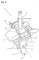
- Figures 6 to 9 again show different 3D views for clarity the interaction of the inner bridge 4, the outer bridge 5 and the Guide parts 2.3 to 2.5 of the housing 2, not shown.
- the outer bridge 5 encompasses the inner bridge 4, the two arms of the Bridges in the lower area also have an axis opening 5.1 into which the Locking elements 12.1 and 12.2 can be used, which are then optionally with the locking element interventions 2.1 and 2.2 of the housing 2 cooperate.
- the Selector lever 3 is in this representation in the middle range of motion mostly corresponds to the automatic shift gate.
- FIG. 7 shows a view similar to FIG. 6, but here the selector lever 3 pivoted to the side and is in relation to the pivoting movement about the second Switch axis 8 in a central position.
- FIG. 8 shows how the selector lever 3 rotates about the second switching axis 8 in one Sequence switching lane is deflected against the vehicle direction. It is clear here to recognize that the axis openings 4.1 and 5.1 are eccentric to each other have positioned.
- FIG. 9 shows the situation from FIG. 8 in a frontal view in Vehicle longitudinal direction.
- Figures 10 to 12 the switching device is broken down into individual parts Service.
- Figure 10 shows the inner bridge 4 with the axis opening 4.1 for the first Switch axis 7 and the lever arm arranged below with the cable connection 13.
- Above the axle opening 4.1 is the axle opening 4.2 for the second one Switching axis 8 and two slots 4.3 arranged on both sides through which the outer bridge 5 is inserted and then rotatably inserted with the inner bolt Bridge 4 is connected.
- a cross member 4.4 In the upper area on the left is a cross member 4.4, the not visible here on the lower side via a detent in the vehicle's longitudinal direction and has a detent in the vehicle transverse direction.
- FIG 11 shows the outer bridge 5, which on the upper cross member with the Selector lever 3 is connected.
- a tie rod 15 which cooperates with a bolt 16.
- the outer bridge 5 has an axis opening 5.1 in the lower area, into which the locking elements 12.1 and 12.2 are used, and in the upper area via an axle opening 5.2 into which a bolt is used to connect the inner and outer bridges becomes.
- the bolt acts as a second switching axis 8.
- Figure 12 shows the central carrier 6 with the selection axis 9 and the side arranged openings 6.1 for the bearing insert 11.
- the arranged on both sides Bearing inserts 11 each have an axle element 11.1, which - mostly of Plastic made - engages in the axis opening 4.1 of the inner bridge 4.
- On the Top of the central support 6 is in the front area Locking curve 6.4, which in cooperation with the tie rod 15 and Latch 16 can limit the movement of the selector lever 3 in the desired manner.
- a locking roller 6.2 and a locking roller 6.3 are on the top arranged.
- the locking roller 6.2 is used for locking a sideways movement, while the locking roller 6.3 for locking a pivoting movement of the inner bridge serves in the direction of the vehicle.
- Figures 13 to 17 show to clarify the idea of the invention schematic representations of the movement spaces of the selector lever of the device according to the invention and optionally arranged therein Movement gates.
- Figures 13 to 15 represent a section A-A of Figures 16 and 17 and show the movement spaces of the example of a switching device according to the invention in one level.
- the movement spaces I, II and III are shown, which in their top view consist of three adjacent rectangles.
- the middle one Rectangle II corresponds to the range of motion assigned to an automatic shift gate can be, while the bilaterally arranged movement spaces I and III, which in are arranged parallel to their longitudinal alignment, which represent movement spaces, which is used for the sequence switching lane or possibly also for two different functions can be used.
- Two shift gates namely the automatic shift gate, are exemplary in FIG. 13a AG and the sequence switching alley SG1 shown, both switching alleys with each other via the dialing street WG1.
- Such a configuration of the Druckgasse is essentially considered if in the Automatic shift gate a detent 6.4, corresponding to that detailed above described example, is present.
- the switching device with the movement spaces shown here Vehicles with different steering wheel positions (right-hand drive or left-hand drive) can be used in a simple way - e.g. by replacing the cover - the Arrangement of the shift lanes can be adjusted to the positioning of the driver's seat. The otherwise complex change in the actual switching device can be omitted.
- FIGS. 14 and 15 show a corresponding example of a switching device the same movement spaces I to III.
- the difference between the two versions a switching device between Figure 14 and Figure 15 is that a mirror-inverted cover with mirror image arranged accordingly Movement lanes is used for the selector lever.
- FIG. 16 the movement spaces I are again shown schematically in a front view, II and III are shown, while Figure 17 is a side view of the same Represents spaces of movement, with the positions in FIG. 17 - in particular the first switching axis 7 and the second switching axis 8 and also the position of the Selector axis 9 - are shown.
- FIG. 18 shows the possible one Positioning of the selector lever including the movement lanes shown.
- This Figure 18 shows a switching device corresponding to Figure 1 with the same view.
- the shown positioning of the bridges 4 and 5 and the central support 6 shows a Situation with selector lever 3 in a middle position in the automatic shift gate.
- the selector lever position 3.1 corresponds to a position of the selector lever 3 in the automatic shift gate in the foremost position ("P" position) while the selector lever is in position 3.2 is shown disengaged in the sequence switch alley on the left.
- Switching device described for using an automatic transmission Sequence switching option is suitable, whereby for a change between right and left-hand drive vehicles the identical switching device can be used.
Landscapes
- Engineering & Computer Science (AREA)
- General Engineering & Computer Science (AREA)
- Mechanical Engineering (AREA)
- Chemical & Material Sciences (AREA)
- Combustion & Propulsion (AREA)
- Transportation (AREA)
- Arrangement Or Mounting Of Control Devices For Change-Speed Gearing (AREA)
- Gear-Shifting Mechanisms (AREA)
Abstract
Description
- einen, um eine Wählachse schwenkbaren Zentralträger aufweist,
- eine am Zentralträger schwenkbar gelagerte innere Brücke aufweist, die um eine im wesentlichen senkrecht zur Wählachse stehende erste Schaltachse
- schwenkbar ist, und
- eine an der inneren Brücke, um eine zweite Schaltachse gelagerte und schwenkbare, äußere Brücke aufweist, die mit dem Wählhebel verbunden ist.
- Figur 1:
- Erfindungsgemäße Schaltvorrichtung in seitlicher 3D-Ansicht von rechts mit Wählhebel in Mittelstellung in der Automatikschaltgasse;
- Figur 2:
- Erfindungsgemäße Schaltvorrichtung in seitlicher 3D-Ansicht von rechts mit Wählhebel in "P"-Stellung in der Automatikschaltgasse;
- Figur 3:
- Erfindungsgemäße Schaltvorrichtung in seitlicher 3D-Ansicht von links mit Wählhebel in "P"-Stellung in der Automatikschaltgasse;
- Figur 4:
- Erfindungsgemäße Schaltvorrichtung in seitlicher 3D-Ansicht von rechts mit Wählhebel in Mittelstellung in der rechten Sequenzschaltgasse;
- Figur 5:
- Erfindungsgemäße Schaltvorrichtung in seitlicher 3D-Ansicht von rechts mit zurückgezogenem Wählhebel in der rechten Sequenzschaltgasse;
- Figur 6:
- Seitliche 3D-Ansicht der inneren und äußeren Brücke mit Teilen des Gehäuses von rechts mit Wählhebel in Mittelstellung in der Automatikschaltgasse;
- Figur 7:
- Seitliche 3D-Ansicht der inneren und äußeren Brücke mit Teilen des Gehäuses von rechts mit Wählhebel in Mittelstellung in der Sequenzschaltgasse;
- Figur 8:
- Seitliche 3D-Ansicht der inneren und äußeren Brücke mit Teilen des Gehäuses von rechts mit zurückgezogenem Wählhebel in der Sequenzschaltgasse;
- Figur 9:
- 3D-Ansicht der inneren und äußeren Brücke mit Teilen des Gehäuses von hinten mit Wählhebel in der Sequenzschaltgasse;
- Figur 10:
- Seitliche 3D-Ansicht der inneren Brücke;
- Figur 11:
- Seitliche 3D-Ansicht der äußeren Brücke;
- Figur 12:
- Seitliche 3D-Ansicht des Zentralträgers;
- Figur 13-14
- Schematische Darstellungen der Bewegungsräume I, II und III;
- Figur 15:
- Schematische Ansicht der Bewegungsräume und Bewegungsgassen im Schnitt A-A der Figuren 16 und 17;
- Figur 16:
- Schematische Ansicht der Bewegungsräume und Bewegungsgassen im Schnitt von hinten;
- Figur 17:
- Schematische Ansicht der Bewegungsräume und Bewegungsgassen im Schnitt von der Seite;
- Figur 18:
- 3D-Ansicht der Schaltvorrichtung mit Wählhebel in zwei unterschiedlichen Positionen in der Automatikschaltgasse und einer Mittelposition in der Sequenzschaltgasse.
- 1
- Schaltvorrichtung
- 2
- Gehäuse
- 2.1, 2.2
- Sperrelementeingriffe
- 2.3 - 2.5
- Führungselemente
- 3
- Wählhebel
- 3.1, 3.2, 3.3
- Wählhebelpositionen
- 4
- innere Brücke
- 4.1, 4.2
- Achsöffnungen
- 4.3
- Einschubschlitze
- 4.4
- Querträger
- 5
- äußere Brücke
- 5.1, 5.2
- Achsöffnungen
- 6
- Zentralträger
- 6.1
- Öffnung (T-förmig)
- 6.2
- Rastierungsrolle
- 6.3
- Rastierungsrolle
- 6.4
- Verriegelungskurvatur
- 7
- erste Schaltachse
- 8
- zweite Schaltachse
- 9
- Wählachse
- 10
- "Key Lock"-System
- 11
- Lagereinsatz
- 11.1
- Achselement
- 12.1, 12.2
- Sperrelemente
- 13
- Seilzuganbindung
- 14
- "Shift Lock"-System
- 15
- Zugstange
- 16
- Riegel
- I
- linker Bewegungsraum
- II
- mittlerer Bewegungsraum
- III
- rechter Bewegungsraum
- AG
- Automatikschaltgasse
- SG1
- Sequenzschaltgasse 1
- SG2
- Sequenzschaltgasse 2
- WG1
- Wählgasse 1
- WG2
- Wählgasse 2
Claims (19)
- Schaltvorrichtung eines Kraftfahrzeuggetriebes mit einem Wählhebel (3) und einer Kinematik (4 - 9) zur Übertragung der Wählbewegungen auf das Kraftfahrzeuggetriebe, wobei der Wählhebel in einer Automatikschaltgasse zur Anwahl von Automatikgetriebestufen und in einer Sequenzschaltgasse zum manuellen Auf- und Abwärtsschalten von Getriebestufen bewegt werden kann,
dadurch gekennzeichnet, dass für den Wählhebel in der Automatikschaltgasse eine erste Schaltachse (7) und in der Sequenzschaltgasse eine zweite Schaltachse (8) vorgesehen ist, wobei der Wählhebel (3) je nach gewählter Schaltgasse nur um eine der Schaltachsen beweglich ist. - Schaltvorrichtung nach dem vorstehenden Anspruch 1,
dadurch gekennzeichnet, dass die erste und die zweite Schaltachse (7, 8) exzentrisch zueinander angeordnet sind. - Schaltvorrichtung nach einem der vorstehenden Ansprüche 1-2,
dadurch gekennzeichnet, dass die erste und die zweite Schaltachse (7, 8) zueinander parallel angeordnet sind. - Schaltvorrichtung nach einem der vorstehenden Ansprüche 1-3,
dadurch gekennzeichnet, dass die Abstände der ersten und der zweiten Schaltachse (7, 8) zu einem Schaltknauf am Ende des Wählhebels (3) sich wesentlich unterscheiden. - Schaltvorrichtung nach einem der vorstehenden Ansprüche,
dadurch gekennzeichnet, dass der Wählhebel (3) eine etwa in Fahrzeuglängsrichtung liegende Wählachse (9) aufweist, um die er schwenkbar gelagert ist. - Schaltvorrichtung nach einem der vorstehenden Ansprüche,
dadurch gekennzeichnet, dass zur Übertragung der Schaltbewegung des Wählhebels (3) zum Kraftfahrzeuggetriebe in zumindest einer Gasse ein Seilzug vorgesehen ist. - Schaltvorrichtung nach einem der Ansprüche 1-5,
dadurch gekennzeichnet, dass zur Übertragung der Schaltbewegung des Wählhebels (3) zum Kraftfahrzeuggetriebe in zumindest einer Gasse ein Gestänge vorgesehen ist. - Schaltvorrichtung nach einem der vorstehenden Ansprüche,
dadurch gekennzeichnet, dass für die Übertragung der Schaltbewegung des Wählhebels (3) zum Kraftfahrzeuggetriebe in mindestens einer Schaltgasse, vorzugsweise der Sequenzschaltgasse, eine elektronische Übertragungsvorrichtung vorgesehen ist. - Schaltvorrichtung nach einem der vorstehenden Ansprüche,
dadurch gekennzeichnet, dass sie über ein "Key Lock"-System (10) verfügt. - Schaltvorrichtung nach einem der vorstehenden Ansprüche,
dadurch gekennzeichnet, dass sie über ein "Shift Lock"-System (14) verfügt. - Schaltvorrichtung nach einem der vorstehenden Ansprüche,
dadurch gekennzeichnet, dass die Schaltvorrichtung:einen, um eine Wählachse (9) schwenkbaren Zentralträger (6) aufweist,eine am Zentralträger (6) schwenkbar gelagerte innere Brücke (4) aufweist, die um eine im wesentlichen senkrecht zur Wählachse (9) stehende erste Schaltachse (7) schwenkbar ist, undeine an der inneren Brücke (4), um eine zweite Schaltachse (8) gelagerte und schwenkbare, äußere Brücke (5) aufweist, die mit dem Wählhebel (3) verbunden ist. - Schaltvorrichtung gemäß Anspruch 11,
dadurch gekennzeichnet, dass mindestens ein Sperrelementeingriff (2.1, 2.2) und mindestens ein Sperrelement (12.1, 12.2) vorgesehen sind, die mit der inneren und äußeren Brücke (4, 5) derart zusammenwirken, dass bei bestimmten Schwenkstellungen des Zentralträgers (6) mindestens ein Sperrelement (12.1, 12.2) und mindestens ein Sperrelementeingriff (2.1,2.2) sich im gegenseitigen Eingriff befinden, während sie sich in anderen Schwenkstellungen des Zentralträgers (6) außer Eingriff befinden. - Schaltvorrichtung gemäß Anspruch 12,
dadurch gekennzeichnet, dass die erste Schaltachse (7) durch das mindestens eine Sperrelement (12.1, 12.2) verläuft. - Schaltvorrichtung gemäß einem der vorstehenden Ansprüche 12-13,
dadurch gekennzeichnet, dass das mindestens eine Sperrelement (12.1, 12.2) und der mindestens eine Sperrelementeingriff (2.1, 2.2) im Falle des gegenseitigen Eingriffs eine drehfeste Verbindung zwischen der inneren Brücke (4) und der äußeren Brücke (5) bilden. - Schaltvorrichtung gemäß einem der vorstehenden Ansprüche 12-14,
dadurch gekennzeichnet, dass der mindestens eine Sperrelementeingriff (2.1, 2.2) mit dem Gehäuse (2) der Schaltvorrichtung einstückig verbunden ist. - Schaltvorrichtung gemäß einem der vorstehenden Ansprüche,
dadurch gekennzeichnet, dass Mittel (2.3-2.5) zur Begrenzung von Bewegungsgassen und/oder Bewegungsräumen vorgesehen sind. - Schaltvorrichtung gemäß Anspruch 16,
dadurch gekennzeichnet, dass die Mittel (2.3-2.5) zur Begrenzung von Bewegungsgassen und/oder Bewegungsräumen zumindest teilweise am Gehäuse (2) befestigt sind. - Schaltvorrichtung gemäß einem der vorstehenden Ansprüche 16-17,
dadurch gekennzeichnet, dass die Mittel (2.3-2.5) zur Begrenzung von Bewegungsgassen und/oder Bewegungsräumen zumindest teilweise an der inneren Brücke (4) befestigt sind. - Schaltvorrichtung gemäß einem der vorstehenden Ansprüche 16-18,
dadurch gekennzeichnet, dass die Mittel (2.3-2.5) zur Begrenzung von Bewegungsgassen und/oder Bewegungsräumen zumindest teilweise an der äußeren Brücke (5) befestigt sind.
Applications Claiming Priority (3)
| Application Number | Priority Date | Filing Date | Title |
|---|---|---|---|
| DE19853934A DE19853934B4 (de) | 1998-11-23 | 1998-11-23 | Schaltvorrichtung eines Kraftfahrzeuggetriebes |
| DE19853934 | 1998-11-23 | ||
| EP99964355A EP1064168B1 (de) | 1998-11-23 | 1999-11-22 | Schaltvorrichtung eines kraftfahrzeuggetriebes |
Related Parent Applications (1)
| Application Number | Title | Priority Date | Filing Date |
|---|---|---|---|
| EP99964355A Division EP1064168B1 (de) | 1998-11-23 | 1999-11-22 | Schaltvorrichtung eines kraftfahrzeuggetriebes |
Publications (2)
| Publication Number | Publication Date |
|---|---|
| EP1365177A2 true EP1365177A2 (de) | 2003-11-26 |
| EP1365177A3 EP1365177A3 (de) | 2004-07-14 |
Family
ID=7888686
Family Applications (3)
| Application Number | Title | Priority Date | Filing Date |
|---|---|---|---|
| EP03019794A Withdrawn EP1365177A3 (de) | 1998-11-23 | 1999-11-22 | Schaltvorrichtung eines Kraftfahrzeuggetriebes |
| EP99964355A Expired - Lifetime EP1064168B1 (de) | 1998-11-23 | 1999-11-22 | Schaltvorrichtung eines kraftfahrzeuggetriebes |
| EP03019798A Expired - Lifetime EP1365178B1 (de) | 1998-11-23 | 1999-11-22 | Schaltvorrichtung eines Kraftfahrzeuggetriebes |
Family Applications After (2)
| Application Number | Title | Priority Date | Filing Date |
|---|---|---|---|
| EP99964355A Expired - Lifetime EP1064168B1 (de) | 1998-11-23 | 1999-11-22 | Schaltvorrichtung eines kraftfahrzeuggetriebes |
| EP03019798A Expired - Lifetime EP1365178B1 (de) | 1998-11-23 | 1999-11-22 | Schaltvorrichtung eines Kraftfahrzeuggetriebes |
Country Status (8)
| Country | Link |
|---|---|
| US (1) | US6386061B1 (de) |
| EP (3) | EP1365177A3 (de) |
| JP (1) | JP3497473B2 (de) |
| KR (1) | KR100542035B1 (de) |
| CN (1) | CN1183343C (de) |
| DE (1) | DE19853934B4 (de) |
| ES (2) | ES2248695T3 (de) |
| WO (1) | WO2000030885A2 (de) |
Families Citing this family (19)
| Publication number | Priority date | Publication date | Assignee | Title |
|---|---|---|---|---|
| EP1210242A4 (de) * | 1999-07-29 | 2006-01-25 | Grand Haven Stamped Products | Schalthebel mit parksperre und neutralblockierung |
| DE19937698C2 (de) | 1999-08-10 | 2001-09-13 | Zf Lemfoerder Metallwaren Ag | Schaltvorrichtung eines automatischen Kraftfahrzeuggetriebes |
| DE10015079C2 (de) * | 2000-03-28 | 2002-01-24 | Zf Lemfoerder Metallwaren Ag | Schaltvorrichtung für ein Automatikgetriebe eines Kraftfahrzeuges |
| DE10060803A1 (de) * | 2000-12-07 | 2002-07-04 | Deere & Co | Schaltvorrichtung für ein Fahrzeuggetriebe |
| DE10105491B4 (de) * | 2001-02-07 | 2010-05-12 | Jopp Gmbh | Schaltvorrichtung für ein Getriebe |
| AU2002951613A0 (en) * | 2002-09-24 | 2002-10-10 | M.T.M. Pty Ltd | A shift lever assembly |
| DE10249074B4 (de) | 2002-10-21 | 2006-05-04 | ZF Lemförder Metallwaren AG | Schaltvorrichtung für ein automatisches Getriebe |
| KR20040038206A (ko) * | 2002-10-31 | 2004-05-08 | 현대자동차주식회사 | 수동변속기용 케이블의 어저스트 기구 |
| DE10252009B4 (de) | 2002-11-06 | 2005-03-31 | ZF Lemförder Metallwaren AG | Schaltvorrichtung zur Übertragung von Schaltbefehlen an ein Automatikgetriebe |
| DE10344287B4 (de) * | 2003-09-23 | 2005-12-08 | Zf Friedrichshafen Ag | Rastiervorrichtung |
| JP4450634B2 (ja) * | 2004-01-14 | 2010-04-14 | 株式会社東海理化電機製作所 | シフトレバー装置 |
| DE102004033672B4 (de) * | 2004-07-09 | 2006-09-21 | Zf Friedrichshafen Ag | Schaltvorrichtung für ein Automatikgetriebe |
| JP4389985B2 (ja) * | 2007-09-04 | 2009-12-24 | トヨタ自動車株式会社 | 状態切替要素の作動装置、自動変速機のレンジ切替装置、ならびにパーキング装置 |
| DE102007058922B3 (de) * | 2007-12-05 | 2009-06-18 | Zf Friedrichshafen Ag | Betätigungseinrichtung mit Kulissenwelle |
| CN101545538B (zh) * | 2009-05-12 | 2012-12-05 | 湘潭电机股份有限公司 | 一种变速箱换档执行机构 |
| DE102015102607A1 (de) | 2015-02-24 | 2016-08-25 | Küster Holding GmbH | Schaltvorrichtung für ein Automatikgetriebe eines Kraftfahrzeuges |
| DE102016119842B3 (de) * | 2016-10-18 | 2018-02-22 | Preh Gmbh | Betriebsarten-Wähleinrichtung für ein Fahrzeuggetriebe mit Schlittenmechanik |
| CN108547941A (zh) * | 2018-06-21 | 2018-09-18 | 洛阳市黄河软轴控制器股份有限公司 | 车辆操纵控制机构及其使用方法 |
| CN112664644B (zh) * | 2021-01-23 | 2022-02-18 | 上海海穆电子科技有限公司 | 一种挡位可调的手柄结构 |
Citations (2)
| Publication number | Priority date | Publication date | Assignee | Title |
|---|---|---|---|---|
| DE19526059A1 (de) | 1995-07-17 | 1997-01-23 | Lemfoerder Metallwaren Ag | Schaltvorrichtung für ein automatisches Getriebe in einem Kraftfahrzeug |
| DE19756034A1 (de) | 1997-12-17 | 1999-07-01 | Lemfoerder Metallwaren Ag | Wählvorrichtung für ein Fahrzeuggetriebe |
Family Cites Families (10)
| Publication number | Priority date | Publication date | Assignee | Title |
|---|---|---|---|---|
| DE24333C (de) | L. WECHSELMANN in Lublinitz | Entkuppelungsvorrichtung für Vieh im Stalle | ||
| BR7603032A (pt) * | 1975-05-14 | 1977-05-31 | Massey Ferguson Services Nv | Aperfeicoamento em transmissao de mudanca de velocidade |
| NL8700145A (nl) | 1987-01-21 | 1988-08-16 | Volvo Car Bv | Geleide- en bedieningsstelsel voor de bedieningshendel van een automobieltransmissie. |
| JP3116584B2 (ja) * | 1992-07-22 | 2000-12-11 | アイシン・エィ・ダブリュ株式会社 | 車両用自動変速機の変速操作装置 |
| US5415056A (en) * | 1992-09-21 | 1995-05-16 | Toyota Jidosha Kabushiki Kaisha | Shift control system for manually shiftable automatic transmission |
| DE4332265C1 (de) * | 1993-09-23 | 1995-05-04 | Daimler Benz Ag | Anordnung zum Steuern des Gangwechsels eines selbsttätig schaltenden Gangwechselgetriebes eines Kraftfahrzeuges |
| JPH07151224A (ja) * | 1993-11-30 | 1995-06-13 | Fuji Kiko Co Ltd | 自動変速機の操作装置 |
| DE19526509A1 (de) | 1995-07-20 | 1997-01-23 | Still Gmbh | Elektrische Maschine |
| DE19620532C2 (de) * | 1996-05-22 | 1998-07-30 | Lemfoerder Metallwaren Ag | Schaltvorrichtung für ein Automatikgetriebe eines Kraftfahrzeuges |
| DE19620515C2 (de) * | 1996-05-22 | 1998-04-30 | Lemfoerder Metallwaren Ag | Schaltvorrichtung für ein Automatikgetriebe eines Kraftfahrzeuges |
-
1998
- 1998-11-23 DE DE19853934A patent/DE19853934B4/de not_active Expired - Lifetime
-
1999
- 1999-11-22 EP EP03019794A patent/EP1365177A3/de not_active Withdrawn
- 1999-11-22 CN CNB998022934A patent/CN1183343C/zh not_active Expired - Lifetime
- 1999-11-22 EP EP99964355A patent/EP1064168B1/de not_active Expired - Lifetime
- 1999-11-22 EP EP03019798A patent/EP1365178B1/de not_active Expired - Lifetime
- 1999-11-22 ES ES03019798T patent/ES2248695T3/es not_active Expired - Lifetime
- 1999-11-22 WO PCT/DE1999/003705 patent/WO2000030885A2/de not_active Ceased
- 1999-11-22 US US09/600,812 patent/US6386061B1/en not_active Expired - Lifetime
- 1999-11-22 KR KR1020007007713A patent/KR100542035B1/ko not_active Expired - Fee Related
- 1999-11-22 JP JP2000583734A patent/JP3497473B2/ja not_active Expired - Fee Related
- 1999-11-22 ES ES99964355T patent/ES2226486T3/es not_active Expired - Lifetime
Patent Citations (2)
| Publication number | Priority date | Publication date | Assignee | Title |
|---|---|---|---|---|
| DE19526059A1 (de) | 1995-07-17 | 1997-01-23 | Lemfoerder Metallwaren Ag | Schaltvorrichtung für ein automatisches Getriebe in einem Kraftfahrzeug |
| DE19756034A1 (de) | 1997-12-17 | 1999-07-01 | Lemfoerder Metallwaren Ag | Wählvorrichtung für ein Fahrzeuggetriebe |
Also Published As
| Publication number | Publication date |
|---|---|
| WO2000030885A3 (de) | 2000-11-09 |
| JP3497473B2 (ja) | 2004-02-16 |
| EP1365178B1 (de) | 2005-10-05 |
| DE19853934B4 (de) | 2006-05-04 |
| DE19853934A1 (de) | 2000-05-25 |
| CN1307669A (zh) | 2001-08-08 |
| ES2248695T3 (es) | 2006-03-16 |
| EP1064168A2 (de) | 2001-01-03 |
| CN1183343C (zh) | 2005-01-05 |
| EP1365177A3 (de) | 2004-07-14 |
| KR20010034103A (ko) | 2001-04-25 |
| EP1365178A2 (de) | 2003-11-26 |
| ES2226486T3 (es) | 2005-03-16 |
| EP1365178A3 (de) | 2004-07-14 |
| JP2002530237A (ja) | 2002-09-17 |
| KR100542035B1 (ko) | 2006-01-12 |
| EP1064168B1 (de) | 2004-09-08 |
| WO2000030885A2 (de) | 2000-06-02 |
| US6386061B1 (en) | 2002-05-14 |
Similar Documents
| Publication | Publication Date | Title |
|---|---|---|
| EP1064168B1 (de) | Schaltvorrichtung eines kraftfahrzeuggetriebes | |
| DE69706449T2 (de) | Gangschaltvorrichtung für ein Fahrzeug | |
| DE19744238B4 (de) | Park-Sperrmechanismus für Automatikgetriebe | |
| EP2217836A1 (de) | Schaltvorrichtung für ein getriebe | |
| DE3023378C2 (de) | Schaltvorrichtung für eine Zapfwelle | |
| DE69905724T2 (de) | Steuereinrichtung | |
| DE2938640C2 (de) | Schalteinrichtung für hydromechanische Schaltgetriebe, insb. für Ackerschlepper oder ähnliche Nutzfahrzeuge | |
| EP1117950B1 (de) | Schaltvorrichtung eines automatischen kraftfahrzeuggetriebes | |
| DE8402033U1 (de) | Selbstfahrende handgeführte Maschine | |
| DE69127909T2 (de) | Schiebe-Hebe-Dach-Vorrichtung für Kraftfahrzeug | |
| DE2622599A1 (de) | Geradlinig gefuehrte schalteinrichtung, insbesondere fuer vierradantriebs-fahrzeuge | |
| DE2653035C3 (de) | Schaltvorrichtung für ein Kraftfahrzeugwechselgetriebe | |
| DE68910890T2 (de) | Mechanismus und dessen arbeitsweise zum positionieren eines gangschalthebels in parkstellung. | |
| DE2903192A1 (de) | Modellfahrzeug zur bewegung laengs einer fahrbahn | |
| DE69602894T2 (de) | Schiebehebedach und ein mit einem solchen Schiebehebedach ausgerüstetes Kraftfahrzeug | |
| DE69815552T2 (de) | Manövriervorrichtung | |
| EP1531290B1 (de) | Schalteinrichtung | |
| DE1963545B2 (de) | Schaltbereich-Wählvorrichtungen für ein selbstschaltendes Wechselgetriebe von Kraftfahrzeugen | |
| DE3333423A1 (de) | Mechanische schalteinrichtung | |
| DE69705783T2 (de) | Verbessertes motorisiertes landwirtschaftliches Arbeitsgerät | |
| DE2508679C2 (de) | Gangschalteinrichtung für Fahrzeuge mit kippbarem Fahrerhaus | |
| DE60027362T2 (de) | Verriegelung für eine Fahrzeugschalthebelbaugruppe | |
| EP1245872B1 (de) | Schaltvorrichtung für ein Zahnräderwechselgetriebe, insbesondere für Kraftfahrzeuge | |
| EP0769439B2 (de) | Weichenantrieb mit einstellbarem Hub | |
| DE3121902A1 (de) | "landwirtschaftliche einachsbodenbearbeitungsmaschine" |
Legal Events
| Date | Code | Title | Description |
|---|---|---|---|
| PUAI | Public reference made under article 153(3) epc to a published international application that has entered the european phase |
Free format text: ORIGINAL CODE: 0009012 |
|
| AC | Divisional application: reference to earlier application |
Ref document number: 1064168 Country of ref document: EP Kind code of ref document: P |
|
| AK | Designated contracting states |
Kind code of ref document: A2 Designated state(s): ES FR GB IT SE |
|
| PUAL | Search report despatched |
Free format text: ORIGINAL CODE: 0009013 |
|
| AK | Designated contracting states |
Kind code of ref document: A3 Designated state(s): ES FR GB IT SE |
|
| 17P | Request for examination filed |
Effective date: 20040621 |
|
| AKX | Designation fees paid |
Designated state(s): ES FR GB IT SE |
|
| 17Q | First examination report despatched |
Effective date: 20050406 |
|
| STAA | Information on the status of an ep patent application or granted ep patent |
Free format text: STATUS: THE APPLICATION IS DEEMED TO BE WITHDRAWN |
|
| 18D | Application deemed to be withdrawn |
Effective date: 20051018 |