EP1365256A1 - Appareil, materiel et procede de mesure de distance - Google Patents
Appareil, materiel et procede de mesure de distance Download PDFInfo
- Publication number
- EP1365256A1 EP1365256A1 EP02701614A EP02701614A EP1365256A1 EP 1365256 A1 EP1365256 A1 EP 1365256A1 EP 02701614 A EP02701614 A EP 02701614A EP 02701614 A EP02701614 A EP 02701614A EP 1365256 A1 EP1365256 A1 EP 1365256A1
- Authority
- EP
- European Patent Office
- Prior art keywords
- frequency
- amplitude
- distance
- signal
- measuring
- Prior art date
- Legal status (The legal status is an assumption and is not a legal conclusion. Google has not performed a legal analysis and makes no representation as to the accuracy of the status listed.)
- Withdrawn
Links
Images



Classifications
-
- G—PHYSICS
- G01—MEASURING; TESTING
- G01S—RADIO DIRECTION-FINDING; RADIO NAVIGATION; DETERMINING DISTANCE OR VELOCITY BY USE OF RADIO WAVES; LOCATING OR PRESENCE-DETECTING BY USE OF THE REFLECTION OR RERADIATION OF RADIO WAVES; ANALOGOUS ARRANGEMENTS USING OTHER WAVES
- G01S17/00—Systems using the reflection or reradiation of electromagnetic waves other than radio waves, e.g. lidar systems
- G01S17/02—Systems using the reflection of electromagnetic waves other than radio waves
- G01S17/06—Systems determining position data of a target
- G01S17/08—Systems determining position data of a target for measuring distance only
- G01S17/32—Systems determining position data of a target for measuring distance only using transmission of continuous waves, whether amplitude-, frequency-, or phase-modulated, or unmodulated
-
- G—PHYSICS
- G01—MEASURING; TESTING
- G01B—MEASURING LENGTH, THICKNESS OR SIMILAR LINEAR DIMENSIONS; MEASURING ANGLES; MEASURING AREAS; MEASURING IRREGULARITIES OF SURFACES OR CONTOURS
- G01B15/00—Measuring arrangements characterised by the use of electromagnetic waves or particle radiation, e.g. by the use of microwaves, X-rays, gamma rays or electrons
-
- G—PHYSICS
- G01—MEASURING; TESTING
- G01S—RADIO DIRECTION-FINDING; RADIO NAVIGATION; DETERMINING DISTANCE OR VELOCITY BY USE OF RADIO WAVES; LOCATING OR PRESENCE-DETECTING BY USE OF THE REFLECTION OR RERADIATION OF RADIO WAVES; ANALOGOUS ARRANGEMENTS USING OTHER WAVES
- G01S13/00—Systems using the reflection or reradiation of radio waves, e.g. radar systems; Analogous systems using reflection or reradiation of waves whose nature or wavelength is irrelevant or unspecified
- G01S13/02—Systems using reflection of radio waves, e.g. primary radar systems; Analogous systems
- G01S13/06—Systems determining position data of a target
- G01S13/08—Systems for measuring distance only
- G01S13/32—Systems for measuring distance only using transmission of continuous waves, whether amplitude-, frequency-, or phase-modulated, or unmodulated
Definitions
- This invention relates to a distance-measuring device.
- a progressive wave such as an electric wave or a light wave emitted from an antenna or a light source toward an object is reflected by the object to become a reflected wave.
- the progressive wave and the reflected wave interfere with each other to become a standing wave between the antenna or the light source and the object.
- This invention relates to a device, equipment, and a method for measuring distances to various objects by using such standing waves.
- Electric-wave radars such as microwave radars and millimeter-wave radars, are well known as electric wave-based distance-measuring devices. Electric-wave radars are classified into pulse radar, FMCW radar, and so on. Spread-spectrum radars and CDMA radars have recently come into use.
- the pulse radar finds the distance to an object by sending out a pulse signal toward the object and measuring the time from the sending out to the return of the pulse signal.
- the spread-spectrum radar and the CDMA radar find the distance to an object in basically the same way as the pulse radar.
- the FMCW radar finds the distance to an object by sending out a frequency-modulated continuous wave and determining the difference in frequency between the signal sent out and its reflection from the object.
- the FMCW radar is capable of measuring the moving speed of the object simultaneously.
- Doppler radar which has a simple construction and is capable of measuring short distances; however, it is incapable of measuring the distance to a standstill object.
- on-vehicle radars are coming into use to prevent vehicles from running into obstacles or pedestrians. They are expected to be capable of (i) measuring a distance as short as several ten centimeters, (ii) measuring the distance from a vehicle to another vehicle, the latter being at a stop relatively to the former and an on-vehicle radar installed on the former, and (iii) measuring the distances to objects accurately even under the interference from other on-vehicle radars.
- the on-vehicle radars available at present do not meet these three conditions. In the circumstances, the development of an on-vehicle radar capable of meeting the three conditions is hoped for.
- a distance-measuring device for measuring the distance to an object.
- the distance-measuring device comprises (i) a frequency-controlling means which outputs a frequency-control signal whose frequency is changing, (ii) a transmitting means which is connected to the frequency-controlling means and sends out an electromagnetic wave, whose frequency is the same as the frequency of the frequency-control signal, into a propagating medium between itself and the object, toward the object, (iii) a detecting means which is provided between the transmitting means and the object, detects the amplitude of a standing wave formed in the propagating medium, and outputs an amplitude signal corresponding to the detected amplitude, and (iv) a signal-processing unit which receives information about the frequency of the frequency-control signal and the amplitude signal, forms a frequency-amplitude function representing the relation between the frequency of the frequency-control signal and the value of the amplitude signal, and calculates the distance between the detecting means and the object
- a distance-measuring device for measuring the distance to an object.
- the distance-measuring device comprises (i) a frequency-controlling means which outputs a frequency-control signal whose frequency is changing, (ii) a transmitting means which is connected to the frequency-controlling means and sends out an electromagnetic wave, whose frequency is the same as the frequency of the frequency-control signal, into a propagating medium between itself and the object, toward the object, (iii) a detecting means which is provided between the transmitting means and the object, detects the amplitude of a standing wave formed in the propagating medium, and outputs an amplitude signal corresponding to the detected amplitude, and (iv) a signal-processing unit which receives information about the frequency of the frequency-control signal and the amplitude signal, forms a frequency-amplitude function representing the relation between the frequency of the frequency-control signal and the value of the amplitude signal, finds two or more frequencies ⁇ n to ⁇
- the distance-measuring device of the second feature further comprises a modulator for the frequency modulation of the frequency-control signal.
- Its detecting means includes (i) a receiving unit which detects the amplitude of the standing wave and outputs an amplitude signal corresponding to the amplitude, and (ii) a wave-detecting unit which receives a frequency-modulation signal from the modulator, does the synchronous detection of the amplitude signal by using the frequency-modulation signal to form a demodulated signal, and outputs an amplitude signal corresponding to the amplitude of the demodulated signal.
- a distance-measuring device for measuring the distance to an object.
- the distance-measuring device comprises (i) a light source which emits a light beam (hereinafter the "original beam") whose intensity is changing periodically with changing frequency, (ii) a light-splitting means which splits the original beam into two beams and directs one beam after split to the object through a propagating medium between itself and the object, (iii) a means which causes the reflection of the beam after split directed to the object and the other beam after split to interfere with each other to become a standing wave, (iv) a detecting means which detects the amplitude of the standing wave and outputs an amplitude signal corresponding to the amplitude, and (v) a signal-processing unit which receives information about the frequency of the periodic change of intensity of the original beam and the amplitude signal, forms a frequency-amplitude function representing the relation between the frequency of periodic change of intensity of the original beam and the value of the
- a distance-measuring device for measuring the distance to an object.
- the distance-measuring device comprises (i) a light source which emits a light beam (hereinafter the "original beam") whose intensity is changing periodically with changing frequency, (ii) a light-splitting means which splits the original beam into two beams and directs one beam after split to the object through a propagating medium between itself and the object, (iii) a means which causes the reflection of the beam after split directed to the object and the other beam after split to interfere with each other to become a standing wave, (iv) a detecting means which detects the amplitude of the standing wave and outputs an amplitude signal corresponding to the amplitude, and (v) a signal-processing unit which receives information about the frequency of periodic change of intensity of the original beam and the amplitude signal, forms a frequency-amplitude function representing the relation between the frequency of periodic change of intensity of the original beam and the value of the ampli
- the distance-measuring device of the fifth feature further comprises a modulator for the frequency modulation of the periodic change of intensity of the original beam.
- Its detecting means includes (i) a receiving unit which detects the amplitude of the standing wave and outputs an amplitude signal corresponding to the amplitude, and (ii) a wave-detecting unit which receives a frequency-modulation signal from the modulator, does the synchronous detection of the amplitude signal by using the frequency-modulation signal to form a demodulated signal, and outputs an amplitude signal corresponding to the amplitude of the demodulated signal.
- a distance-measuring device for measuring the distance to an object.
- the distance-measuring device comprises (i) a plurality of distance-measuring devices of claim 1, 2, 3, 4, 5 or 6, (ii) a controller which controls the distance-measuring devices for their synchronous operation, and (iii) an arithmetic-processing unit which the distance from each distance-measuring device to the object found by said device is inputted into and calculates the coordinates of the object based on the inputted distances and the relative positions of the distance-measuring devices.
- a method of measuring the distance to an object comprises the steps of (i) sending out an electromagnetic wave from a transmitting means into a propagating medium between the transmitting means and the object, toward the object, to form a standing wave between the transmitting means and the object, (ii) detecting the amplitude of the standing wave with a detecting means disposed at a point between the transmitting means and the object, (iii) changing the frequency of the electromagnetic wave and forming a frequency-amplitude function which represents the relation between the frequency of the electromagnetic wave and the amplitude of the standing wave, and (iv) calculating the distance between the detecting means and the object by using the period of the frequency-amplitude function.
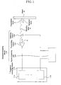
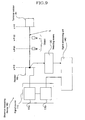
- the reference sign 10A is the distance-measuring device, which basically comprises a frequency-controlling means 11A, a transmitting means 12A, a detecting means 13A, and a signal-processing unit 14A.
- the distance-measuring device 10A is characterized by measuring the distance to an object M by using a standing wave S formed between the transmitting means 12A and the object M.
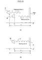
- the standing wave S will be described.
- an electromagnetic-wave generator B1 emits an electromagnetic wave with frequency ⁇ into a propagating medium such as air.
- the electromagnetic wave travels through the medium as a progressive wave D with frequency ⁇ .
- a standing wave S is formed between the electromagnetic-wave generator B1 and the object M.
- the amplitude SP of the standing wave S at the point of the detector B2 changes periodically while the frequency ⁇ of the progressive wave D is changed, and the period of periodic change of amplitude SP of the standing wave S at the point of the detector B2 (at a distance d 1 from the object M) is c / 2d 1 .
- the period of periodic change of the amplitude SP of the standing wave S is in inverse proportion to the distance d 1 between the detector B2 and the object M. Therefore, the distance d 1 between the detector B2 and the object M can be calculated by changing the frequency ⁇ of the progressive wave D and finding the period of periodic change of the standing wave S at the point of the detector B2.
- the frequency-controlling means 11A comprises a signal-output unit 11a and a frequency-control unit 11b.
- the signal-output unit 11a is a unit, such as an AC power supply, capable of outputting a signal of a certain frequency ⁇ .
- the frequency-control unit 11b controls the frequency ⁇ of the frequency-control signal and outputs information about the frequency ⁇ of the frequency-control signal such as the value ⁇ or a signal of the same frequency ⁇ .
- the transmitting means 12A Connected to the frequency-controlling means 11A is the transmitting means 12A, which comprises an antenna, an amplifier, and so on.
- the transmitting means 12A emits an electromagnetic wave, whose frequency is the same as the frequency ⁇ of the frequency-control signal, into such a medium as air or water or into a vacuum between the transmitting means 12A and the object M.
- the frequency of the electromagnetic wave being emitted by the transmitting means 12A is changed by changing the frequency ⁇ of the frequency-control signal by means of the frequency-control unit 11b.
- the detecting means 13A which comprises an antenna, an amplitude detector, and so on.
- the detecting means 13A detects the amplitude SP of a standing wave S, which is formed by the interference between the electromagnetic wave (hereinafter referred to as "progressive wave D") being emitted by the transmitting means 12A and the reflection (hereinafter referred to as "reflected wave R") of the progressive wave D by the object M.
- the detecting means 13A is situated at a distance d 1 from the object M.
- the detecting means 13A outputs an amplitude signal in proportion to SP or the square of SP of the standing wave S.
- the signal-processing unit 14A Connected to the detecting means 13A is the signal-processing unit 14A, which comprises a digital signal processor (DSP), a memory, and so on.
- the signal-processing unit 14A has a storage unit for storing inputted data and an arithmetic-processing unit for calculating the distance d 1 between the detecting means 13A and the object M.
- the signal-processing unit 14A receives information about the frequency ⁇ of the frequency-control signal and sends a receipt-confirmation signal to the frequency-control unit 11b when the value of the amplitude signal from the detecting means 13A has changed.
- the transmitting means 12A and the detecting means 13A may be integrated into a single unit with an antenna. In this case, the distance-measuring device 10A becomes more compact; its structure, simpler.
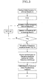
- the initial frequency ⁇ L and the final frequency ⁇ U of the frequency-control signal of the signal-output unit 11a are set by the frequency-control unit 11b.
- the frequency-control unit 11b causes the signal-output unit 11a to output a frequency-control signal of frequency ⁇ L .
- the transmitting means 12A emits a progressive wave D of the same frequency ⁇ L into the propagating medium, toward the object M.
- information about the frequency ⁇ of the frequency-control signal is sent from the frequency-control unit 11b to the signal-processing unit 14A.
- the progressive wave D travels through the propagating medium, reaches the object M, and reflected by the object M to become a reflected wave R.
- the reflected wave R travels through the propagating medium toward the transmitting means 12A, in the direction opposite to that of the progressive wave D. Accordingly, the progressive wave D and the reflected wave R interfere with each other to become a standing wave S in the propagating medium between the transmitting means 12A and the object M.
- the amplitude SP of the standing wave S is detected by the detecting means 13A provided between the transmitting means 12A and the object M, and the detecting means 13A sends the signal-processing unit 14A a signal (hereinafter the "amplitude signal") corresponding to the amplitude SP of the standing wave S.
- the storage unit of the signal-processing unit 14A Upon the receipt of the amplitude signal from the detecting means 13A, the storage unit of the signal-processing unit 14A stores the value P of the amplitude signal, linking the value P to the information about the frequency ⁇ of the frequency-control signal. At the same time, the signal-processing unit 14A sends a receipt-confirmation signal to the frequency-control unit 11b.
- the frequency-control unit 11b Upon the receipt of the receipt-confirmation signal from the signal-processing unit 14A, the frequency-control unit 11b changes the frequency ⁇ of the frequency-control signal by ⁇ ; accordingly, the frequency ⁇ of the progressive wave D changes from ⁇ L to ⁇ L + ⁇ , which causes the wavelength of the progressive wave D to change because the propagation velocity of the progressive wave D (the velocity of the light) remains the same.
- the waveform, including the amplitude SP , of the standing wave S changes and hence the value P of the amplitude signal being sent from the detecting means 13A to the signal-processing unit 14A changes.
- the storage unit of the signal-processing unit 14A stores the changed value P of the amplitude signal, linking the changed value P to the changed information about the frequency ⁇ of the frequency-control signal.
- the frequency-control unit 11b changes the frequency ⁇ of the frequency-control signal of the signal-output unit 11a by ⁇ ⁇ again.
- the arithmetic-processing unit of the signal-processing unit 14A forms a frequency-amplitude function A ( ⁇ , d 1 ) based on the pieces of information about the frequency ⁇ of the frequency-control signal and the values P of the amplitude signal both stored in the storage unit of the signal-processing unit 14A and then transforms the frequency-amplitude function A ( ⁇ , d 1 ) into a period function F ( cy ) through Fourier transformation. Because the period function F (cy) has a peak at the period cy of the frequency-amplitude function A ( ⁇ , d 1 ), the signal-processing unit 14A finds the period cy from the period function F (cy).
- the period cy of the frequency-amplitude function A ( ⁇ , d 1 ), namely, the period of periodic change of the amplitude of the standing wave S is in inverse proportion to the distance d 1 between the detecting means 13A and the object M; therefore, the distance d 1 can be calculated from the period cy.
- the distance-measuring device 10A is capable of measuring the distance d 1 between the detecting means 13A and the object M.
- the distance d 1 between the detecting means 13A and the object M is determined by the period of periodic change of the amplitude of the standing wave S alone and is irrelevant to the time necessary for the progressive wave D to advance from the transmitting means 12A, be reflected by the object M, and return to the detecting means 13A; therefore, if the distance d 1 to the object M is as short as several ten centimeters, the distance can be measured accurately.
- the detecting means 13A If there are formed a plurality of standing waves S's between the transmitting means 12A and a plurality of objects M's, the detecting means 13A outputs an amplitude signal corresponding to the composite value of the amplitudes SP's of the standing waves S's.
- the frequency-amplitude function A ( ⁇ , d 1 ) formed by the arithmetic-processing unit of the signal-processing unit 14A is a composite function composed of the functions showing the periodic changes of amplitudes of standing waves S's relatively to the change of the frequency ⁇ of the frequency-control signal of the signal-output unit 11a, and the period function F ( cy ) formed by the Fourier transformation of the frequency-amplitude function A ( ⁇ , d 1 ) has a peak at the period of each standing wave S [see Fig. 2 (c)].
- the respective periods of periodic changes of the amplitudes of the standing waves S's can be found and hence the respective distances between the detecting means 13A and the objects M's can be measured.
- the frequency ⁇ of the frequency-control signal of the signal-output unit 11a instead of changing the frequency ⁇ of the frequency-control signal of the signal-output unit 11a from the initial frequency ⁇ L to the final frequency ⁇ U by using a certain increment ⁇ , it may be changed at random between ⁇ L and ⁇ U to measure the changing amplitude of the standing wave S and form a frequency-amplitude function A ( ⁇ , d 1 ).
- the frequency ⁇ of the frequency-control signal of the signal-output unit 11a is changed at random in accordance with the M-series code or the like, two or more distance-measuring devices 10A located near to each other are prevented from emitting electromagnetic waves of the same frequency and phase at the same time.
- the amplitude SP of a standing wave S is caused by elements of one and the same frequency; therefore, if the detecting means 13A of a distance-measuring device 10A receives the electromagnetic wave emitted by another distance-measuring device, the elements of the electromagnetic wave can easily be removed with a low-pass filter or the like.
- the measuring accuracy of the distance-measuring device 10A is not disturbed by electromagnetic waves from other distance-measuring devices, and the distance-measuring device 10A is capable of measuring distances even under interference by other distance-measuring devices.
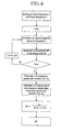
- the distance d 1 between the detecting means 13A and the object M may be calculated from two or more frequencies ⁇ of the frequency-control signal of the signal-output unit 11a which minimize or maximize the value of the frequency-amplitude function A ( ⁇ , d 1 ).
- the signal-processing unit 14A finds two or more frequencies ⁇ n to ⁇ n + k of the frequency-control signal which minimize or maximize the value of the function.
- the signal-processing unit 14A chooses frequencies ⁇ n and ⁇ n + k out of those ⁇ n to ⁇ n+k and calculates the number " k - 1" of frequencies minimizing or maximizing the value of the frequency-amplitude function A ( ⁇ , d 1 ) between the frequencies ⁇ n and ⁇ n + k .
- d 1 k ⁇ c / ⁇ 4 ( ⁇ n+k f n ) ⁇
- the distance d 1 between the detecting means 13A and the object M is calculated by choosing two frequencies ⁇ n and ⁇ n + k and calculating the number " k - 1" of frequencies minimizing or maximizing the value of the frequency-amplitude function A ( ⁇ , d 1 ) between the chosen frequencies.
- the reference sign 10B is the distance-measuring device, which comprises a modulator 20 in addition to a frequency-controlling means 11B including a signal-output unit 11a and a frequency-control unit 11b, a transmitting means 12B, a detecting means 13B, and a signal-processing unit 14B.
- the feature of the distance-measuring device 10B is the modulator 20 which enhances the accuracy of the signal-processing unit 14B in detecting the frequencies f of the frequency-control signal of the signal-output unit 11a which minimize or maximize the value of the frequency-amplitude function A ( ⁇ , d 1 ).
- the modulator 20 is provided between the signal-output unit 11a and the frequency-control unit 11b. If the frequency-control unit 11b sets the frequency-control signal of the signal-output unit 11a for a frequency of ⁇ , the modulator 20 changes the frequency of the frequency-control signal around the set value ⁇ periodically. In other words, the modulator 20 does the frequency modulation of the frequency-control signal of the signal-output unit 11a.
- the modulator 20 sends a frequency-modulation signal to the detecting means 13B.
- the frequency-modulation signal represents the periodically changing component of the frequency-control signal of the signal-output unit 11a.
- the detecting means 13B comprises a receiving unit 13a and a wave-detecting unit 13b.
- the receiving unit 13a detects the amplitude of a standing wave S to be formed between the transmitting means 12B and an object M and outputs an amplitude signal corresponding to the amplitude.
- the receiving unit 13a is connected to the wave-detecting unit 13b.
- the wave-detecting unit 13b comprises a storage unit and an arithmetic-processing unit.
- the storage unit of the wave-detecting unit 13b stores the value of the amplitude signal sent from the receiving unit 13a.
- the arithmetic-processing unit of the wave-detecting unit 13b does synchronous wave detection of the amplitude signal by using the frequency-modulation signal to form a demodulated signal and outputs an amplitude signal corresponding to the amplitude of the demodulated signal.
- the wave-detecting unit 13b Upon the receipt of the amplitude signal from the receiving unit 13a, the wave-detecting unit 13b sends a receipt-confirmation signal to the modulator 20.
- the transmitting means 12B and the detecting means 13B may be integrated into a single unit with an antenna. In this case, the distance-measuring device 10B becomes more compact; its structure, simpler.
- the distance-measuring device 10B finds frequencies of the frequency-control signal minimizing or maximizing the value of the detected-signal function A ( ⁇ , d 1 ) in the same way as the distance-measuring device 10A, the frequency modulation and demodulation alone will be described below.
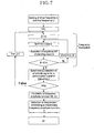
- the frequency-control unit 11b sets the frequency-control signal of the signal-output unit 11a for a frequency of ⁇ .
- the modulator 20 sends a frequency-modulation signal to the wave-detecting unit 13b of the detecting means 13B.
- a standing wave S is formed between the transmitting means 12B and the object M.
- the amplitude SP of the standing wave S at the point of the receiving unit 13a is detected by it and an amplitude signal corresponding to the amplitude SP is sent to the wave-detecting unit 13b.
- the wave-detecting unit 13b Upon the receipt of the amplitude signal from the receiving unit 13a, the wave-detecting unit 13b stores the value P of the amplitude signal, linking the value P to the frequency-modulation signal sent from the modulator 20. At the same time, the wave-detecting unit 13b sends a receipt-confirmation signal to the modulator 20.
- the storage unit of the wave-detecting unit 13b stores the changed value P of the amplitude signal, linking the changed value P to the changed frequency-modulation signal being sent from the modulator 20.
- an arithmetic-processing unit of the wave-detecting unit 13b When ⁇ becomes 2 ⁇ , an arithmetic-processing unit of the wave-detecting unit 13b does the synchronous detection of the amplitude signal by using the frequency-modulation signal to form a demodulated signal and sends the signal-processing unit 14B an amplitude signal corresponding to the amplitude of the demodulated signal.
- the storage unit of the signal-processing unit 14B stores the value of the amplitude signal, linking the value to information about the frequency ⁇ of the frequency-control signal sent from the frequency-control unit 11b to the signal-processing unit 14B.
- the arithmetic-processing unit of the signal-processing unit 14B forms a frequency-amplitude function A ( ⁇ , d 1 ).
- the value of the frequency-amplitude function A ( ⁇ , d 1 ) increases or decreases monotonously in the vicinity of each of the frequencies minimizing or maximizing the amplitude SP of the standing wave S.
- the value P of the frequency-amplitude function A ( ⁇ , d 1 ) changes from plus to minus or from minus to plus in the vicinity of each of the frequencies minimizing or maximizing the amplitude SP of the standing wave S.
- the distance-measuring device 10B is accurate in detecting the frequencies minimizing or maximizing the amplitude SP of the standing wave S and hence is accurate in measuring the distance to the object M.
- the distances to operating machines can be measured.
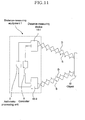
- the reference sign "L" is a signal-transmission line consisting of parallel wires such as micro split lines to send signals to operating machines.
- Operating machines M1 and M2 are arranged along the signal-transmission line L.
- Each of the operating machines M1 and M2 has a metal piece in the vicinity of the signal-transmission line L.
- a signal source 11C such as an AC power supply feeds AC power to the signal-transmission line L through a resistor RS.
- the electric field created by the AC current is disturbed in the vicinities of the metal pieces of the operating machines M1 and M2.
- a standing waves S's are formed between the resistor RS and the operating machines M1 and M2.
- a detecting means 13C such as a square-law wave detector detects the power of the AC current. Then, a signal-processing unit 14C calculates the distances along the signal-transmission line L from the detecting means 13C to the operating machines M1 and M2.
- the distances along the curved line L to the operating machines M1 and M2 can be measured accurately because the standing wave S is formed along the curved line L.
- a mismatching terminal resistor R T is provided on the distal end of the signal-transmission line L, a standing wave S is formed between the resistor RS and the terminal resistor R T . Accordingly, the overall length of the signal-transmission line L can be measured. Therefore, the measured distances to the operating machines M1 and M2 can be corrected by comparing the actual overall length and the measure one of the signal-transmission line L. Thus, the measuring accuracy improves.
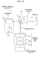
- the reference sign 10D is the distance-measuring device, which comprises a light source 11D, a light-splitting means 31, a mirror 32, a detecting means 13D, and a signal-processing unit 14D.
- the light source 11D of the distance-measuring device 10D emits a light beam whose intensity is periodically changed with changing frequency, and the device 10D measures the distance to an object M by using a standing wave S formed between the light-splitting means 31 and the detecting means 13D.
- the distance-measuring device 10D for calculating the distance to an object M based on the amplitude of the standing wave S detected by the detecting means 13D is the same as those of the distance-measuring devices 10A and 10B, only the construction of the distance-measuring device 10D will be described below.
- the light source 11D comprises a signal-output unit 11a and a frequency-control unit 11b.
- the signal-output unit 11a is a laser, a light-emitting diode, or the like which is capable of emitting a light beam (hereinafter the "original beam") whose intensity changes periodically at a certain frequency ⁇ .
- the frequency-control unit 11b controls the frequency ⁇ of the original beam and outputs information about the frequency ⁇ of the original beam such as the value ⁇ or a signal of the same frequency ⁇ .
- the light-splitting means 31 such as a beam splitter.
- the light-splitting means 31 splits the original beam into two beams. One (hereinafter the "beam 1/2") of the two beams after split is directed to the object M; the other (hereinafter the "beam 2/2"), to the mirror 32.
- the beam 1/2 is reflected by the object M and returns to the light-splitting means 31, which reflects the beam 1/2 toward the detecting means 13D.
- the mirror 32 is disposed on one side of the light-splitting means 31.
- the beam 2/2 is reflected by the mirror 32, and the reflected beam 2/2 returns to and penetrates the light-splitting means 31 toward the detecting means 13D.
- the beams 1/2 and 2/2 interfere with each other between the light-splitting means 31 and the detecting means 13D to become a standing wave S.
- the detecting means 13D is disposed across the light-splitting means 31 from the mirror 32, and the detecting means 13D and the mirror 32 are disposed on a line orthogonal to the light-emitting direction of the signal-output unit 11a.
- the detecting means 13D detects the amplitude SP of the standing wave S.
- the detecting means 13D is provided with a photo detector which detects the amplitude SP of the standing wave S and converts the amplitude SP into an electric signal proportional to SP or the square of SP.
- the signal-processing unit 14D Connected to the detecting means 13D is the signal-processing unit 14D, which comprises a digital signal processor (DSP), a memory, and so on.
- the detecting means 13D has a storage unit for storing inputted data and an arithmetic-processing unit for processing the data in the storage unit to find the distance from the light-splitting means 31 to the object M.
- the signal-processing unit 14D receives information about the frequency ⁇ of the original beam from the frequency-control unit 11b Besides, the signal-processing unit 14D sends a receipt-confirmation signal to the frequency-control unit 11b when it has received an amplitude signal from the detecting means 13D.
- the distance-measuring device 10D is capable of measuring the distance d between the light-splitting means 31 and the object M.
- the distance d to the object M is as short as several ten centimeters, the distance d can be measured accurately.
- the measuring accuracy of the distance-measuring device 10D is not disturbed by light beams from other distance-measuring devices, and the distance-measuring device 10D is capable of measuring distances even under interference by other distance-measuring devices.
- the distance-measuring device 10D is capable of calculating the periods of periodic changes of amplitudes of a plurality of standing waves S's, it is capable of measuring the distances to a plurality of objects M's at the same time.
- the frequency f of the original beam may be changed from an initial frequency ⁇ L of 0 Hz to a final frequency ⁇ U .
- the value of the frequency-amplitude function A ( ⁇ , d 1 ) is maximum. Therefore, the distance d can be calculated just by finding another frequency maximizing the function in the range from above 0 Hz to the final frequency F U .
- the distance-measuring device 10D is provided with a modulator for the frequency modulation of the original beam as in the case of the distance-measuring device 10B, frequencies minimizing or maximizing the frequency-amplitude function A ( ⁇ , d 1 ) are detected accurately and hence the error in measuring the distance to the object M is reduced.
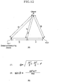
- the reference numeral 1 indicates the distance-measuring equipment, which includes a plurality of distance-measuring devices 10's described earlier. Connected to the distance-measuring devices 10's is a controller 3, which controls the distance-measuring devices 10's for their synchronous operation. Thus, all the distance-measuring devices 10's emit electromagnetic waves into a propagating medium at the same time.
- an arithmetic-processing unit 2 Also connected to the distance-measuring devices 10's is an arithmetic-processing unit 2, in which the distance d to the object M calculated by every distance-measuring device 10 is inputted. The coordinates of the object M are found from the distances d s and the relative positions of the distance-measuring devices 10's.
- the controller 3 synchronizes two distance-measuring devices 10-1 and 10-2, which emit electromagnetic waves at the same time.
- Standing wave S1 and S2 are formed between the object M and the distance-measuring devices 10-1 and 10-2, and the distances d 1 and d 2 from the distance-measuring devices 10-1 and 10-2 to the object M are calculated.
- the calculated values d 1 and d 2 are inputted in the arithmetic-processing unit 2.
- the distance d from the middle point of the straight line (hereinafter "straight line-1") between the two distance-measuring devices 10-1 and 10-2 to the object M and the angle ⁇ included between the straight line orthogonal to the straight line-1 and the straight line from the middle point of the straight line-1 to the object M are calculated by using the equations (1) and (2) shown in Fig. 12 (B).
- the relative positions of the two devices 10-1 and 10-2 and the object M in the plane including them are determined by using the distance d and the angle ⁇ .
- the relative positions of the three devices 10's and the object M are determined in three dimensions.
- the first feature of the present invention brings about the following effects (1) to (4).
- the second feature of the present invention brings about the following effects (1) to (3).
- the third feature of the present invention brings about the following effect.
- the wave-detecting unit does the synchronous detection of the amplitude signal from the receiving unit 13a by using the frequency-modulation signal to form a demodulated signal and outputs an amplitude signal corresponding to the amplitude of the demodulated signal.
- the value of the frequency-amplitude function thus obtained increases or decreases monotonously in the vicinity of each of the frequencies minimizing or maximizing the amplitude of the standing wave.
- the value of the frequency-amplitude function changes from plus to minus or from minus to plus in the vicinity of each of the frequencies minimizing or maximizing the amplitude of the standing wave. Accordingly, the distance-measuring device is accurate in detecting frequencies minimizing or maximizing the amplitude of the standing wave and hence is accurate in measuring the distance to the object.
- the fourth feature of the present invention brings about the following effects (1) to (4).
- the fifth feature of the present invention brings about the following effects (1) to (3).
- the wave-detecting unit does the synchronous detection of an amplitude signal from the receiving unit by using a frequency-modulation signal to form a demodulated signal and outputs an amplitude signal corresponding to the amplitude of the demodulated signal.
- the value of the frequency-amplitude function thus obtained increases or decreases monotonously in the vicinity of each of the frequencies minimizing or maximizing the amplitude of the standing wave.
- the value of the frequency-amplitude function changes from plus to minus or from minus to plus in the vicinity of each of the frequencies minimizing or maximizing the amplitude of the standing wave. Accordingly, the distance-measuring device is accurate in detecting frequencies minimizing or maximizing the amplitude of the standing wave and hence is accurate in measuring the distance to the object.
- the seventh feature of the present invention brings about the following effect. Two or more distance-measuring devices are operated in synchronism, and the distances from them to an object are measured simultaneously. Accordingly, the coordinates of the object can be determined based on the measured distances and the relative positions of the distance-measuring devices. Thus, the relative positions of the distance-measuring devices and the object can be determined in two or three dimensions.
- the eighth feature of the present invention brings about the following effects (1) to (4).
Landscapes
- Physics & Mathematics (AREA)
- Engineering & Computer Science (AREA)
- Radar, Positioning & Navigation (AREA)
- Remote Sensing (AREA)
- General Physics & Mathematics (AREA)
- Electromagnetism (AREA)
- Computer Networks & Wireless Communication (AREA)
- Radar Systems Or Details Thereof (AREA)
- Optical Radar Systems And Details Thereof (AREA)
Applications Claiming Priority (7)
| Application Number | Priority Date | Filing Date | Title |
|---|---|---|---|
| JP2001109270 | 2001-03-01 | ||
| JP2001109270 | 2001-03-01 | ||
| JP2001130355 | 2001-03-24 | ||
| JP2001130355 | 2001-03-24 | ||
| JP2001237280A JP3461498B2 (ja) | 2001-03-01 | 2001-08-06 | 距離測定装置、距離測定設備および距離測定方法 |
| JP2001237280 | 2001-08-06 | ||
| PCT/JP2002/001825 WO2002079799A1 (fr) | 2001-03-01 | 2002-02-27 | Appareil, materiel et procede de mesure de distance |
Publications (2)
| Publication Number | Publication Date |
|---|---|
| EP1365256A1 true EP1365256A1 (fr) | 2003-11-26 |
| EP1365256A4 EP1365256A4 (fr) | 2010-01-20 |
Family
ID=27346491
Family Applications (1)
| Application Number | Title | Priority Date | Filing Date |
|---|---|---|---|
| EP02701614A Withdrawn EP1365256A4 (fr) | 2001-03-01 | 2002-02-27 | Appareil, materiel et procede de mesure de distance |
Country Status (6)
| Country | Link |
|---|---|
| EP (1) | EP1365256A4 (fr) |
| JP (1) | JP3461498B2 (fr) |
| KR (1) | KR100799275B1 (fr) |
| CN (1) | CN100397095C (fr) |
| CA (1) | CA2440969A1 (fr) |
| WO (1) | WO2002079799A1 (fr) |
Cited By (1)
| Publication number | Priority date | Publication date | Assignee | Title |
|---|---|---|---|---|
| US9841505B2 (en) | 2013-12-10 | 2017-12-12 | Lg Electronics Inc. | Electronic device and method for controlling same |
Families Citing this family (26)
| Publication number | Priority date | Publication date | Assignee | Title |
|---|---|---|---|---|
| KR100684811B1 (ko) | 2002-06-07 | 2007-02-20 | 가부시키가이샤 시마세이키 세이사쿠쇼 | 거리측정방법 및 장치 |
| JP3782409B2 (ja) * | 2002-08-30 | 2006-06-07 | 積水樹脂株式会社 | 移動体距離検出システム |
| JP4328555B2 (ja) | 2003-04-21 | 2009-09-09 | Necアクセステクニカ株式会社 | 距離測定方法、及びそれを適用した距離測定装置、並びにそれを適用した距離測定設備 |
| WO2004095058A1 (fr) * | 2003-04-22 | 2004-11-04 | Shima Seiki Manufacturing, Ltd. | Procede de mesure et systeme correspondant |
| WO2004095059A1 (fr) * | 2003-04-22 | 2004-11-04 | Shima Seiki Manufacturing, Ltd. | Procede de mesure de la forme du corps humain et systeme correspondant |
| CN101151551B (zh) * | 2005-03-31 | 2010-10-13 | 松下电器产业株式会社 | 扩展频谱式雷达设备 |
| JP4793627B2 (ja) * | 2005-07-08 | 2011-10-12 | 新日本無線株式会社 | 定在波レーダおよび距離測定方法 |
| JP3784823B1 (ja) * | 2005-07-15 | 2006-06-14 | 国立大学法人徳島大学 | 距離測定装置、距離測定方法および距離測定プログラム |
| US7355548B2 (en) * | 2005-09-01 | 2008-04-08 | Rosemount Tank Radar Ab | Processing of tank signal in radar level gauge system |
| JP4293194B2 (ja) | 2005-09-02 | 2009-07-08 | 財団法人雑賀技術研究所 | 距離測定装置、及び距離測定方法 |
| US7420462B2 (en) * | 2006-01-23 | 2008-09-02 | Bfs Diversified Products, Llc | Air spring distance indicating system and method |
| KR101279103B1 (ko) * | 2009-02-27 | 2013-06-26 | 파나소닉 주식회사 | 거리 측정 장치 |
| WO2011142211A1 (fr) * | 2010-05-11 | 2011-11-17 | アルプス電気株式会社 | Appareil de détection de communication |
| WO2012042636A1 (fr) | 2010-09-30 | 2012-04-05 | トヨタ自動車株式会社 | Dispositif de détection de corps mobile |
| EP2570766B1 (fr) * | 2011-09-16 | 2014-03-19 | Meggitt SA | Dispositif et procédé de surveillance des pales de rotor d'une turbine |
| CN102721381A (zh) * | 2012-06-21 | 2012-10-10 | 三一重工股份有限公司 | 盾尾间隙检测显示系统及其方法和盾构机 |
| CN103697839A (zh) * | 2013-12-20 | 2014-04-02 | 苏州市职业大学 | 一种质量测量仪 |
| CN104914427B (zh) * | 2015-06-15 | 2017-06-16 | 北京科技大学 | 基于接收信号强度的自适应时延估计的测距方法及系统 |
| CN104914426B (zh) * | 2015-06-15 | 2017-06-13 | 北京科技大学 | 一种基于自适应时延估计的近场测距系统及方法 |
| CN107147771B (zh) * | 2016-03-01 | 2021-01-26 | 中兴通讯股份有限公司 | 一种自适应防止进水损害的方法、装置及移动终端 |
| CN105967064A (zh) * | 2016-04-27 | 2016-09-28 | 上海海事大学 | 用于吊具机构的吊摆角与绳长测量装置及测量方法 |
| JP6187995B1 (ja) * | 2016-08-24 | 2017-08-30 | 株式会社Cq−Sネット | 定在波レーダーによる位置検知装置 |
| CN107631860B (zh) * | 2017-09-26 | 2019-10-25 | 成都国翼电子技术有限公司 | 一种计算vr相机所需最少led灯数量的方法 |
| CN112433214B (zh) * | 2019-08-08 | 2024-09-24 | 华为技术有限公司 | 一种雷达信号发送方法及装置 |
| CN113314007B (zh) * | 2021-05-12 | 2022-06-03 | 中国矿业大学(北京) | 基于光学驻波的波长测量方法 |
| CN113484682B (zh) * | 2021-07-15 | 2022-09-09 | 保定市毅格通信自动化有限公司 | 一种基于驻波的配电线路接地故障测距方法 |
Family Cites Families (11)
| Publication number | Priority date | Publication date | Assignee | Title |
|---|---|---|---|---|
| BE362909A (fr) * | 1928-08-10 | |||
| US2151323A (en) * | 1935-05-18 | 1939-03-21 | Telefunken Gmbh | Radio apparatus for determining distance and direction |
| JPS381257B1 (fr) * | 1959-10-03 | 1963-02-20 | ||
| GB2087682B (en) * | 1980-10-27 | 1984-11-21 | Rosemount Eng Co Ltd | Distance measuring apparatus |
| JPS58198781A (ja) * | 1982-05-15 | 1983-11-18 | Ai Takagi | 光線による距離計測装置 |
| JPS59142485A (ja) * | 1983-02-04 | 1984-08-15 | Yamatake Honeywell Co Ltd | 距離測定方式 |
| JPH0735963B2 (ja) * | 1992-01-28 | 1995-04-19 | 株式会社エイ・ティ・アール光電波通信研究所 | 光の屈折率変化が生じる位置を測定する装置 |
| JPH05281341A (ja) * | 1992-03-30 | 1993-10-29 | Isao Iida | 距離測定方法及びその装置 |
| JPH06160082A (ja) * | 1992-11-25 | 1994-06-07 | Matsushita Electric Works Ltd | 光学式測距装置 |
| DE19521771A1 (de) * | 1995-06-20 | 1997-01-02 | Jan Michael Mrosik | FMCW-Abstandsmeßverfahren |
| JPH11230734A (ja) * | 1998-02-10 | 1999-08-27 | Shima Seiki Mfg Ltd | リニアエンコーダ及びこれを用いた横編機 |
-
2001
- 2001-08-06 JP JP2001237280A patent/JP3461498B2/ja not_active Expired - Lifetime
-
2002
- 2002-02-27 EP EP02701614A patent/EP1365256A4/fr not_active Withdrawn
- 2002-02-27 WO PCT/JP2002/001825 patent/WO2002079799A1/fr not_active Ceased
- 2002-02-27 CA CA002440969A patent/CA2440969A1/fr not_active Abandoned
- 2002-02-27 KR KR1020037011442A patent/KR100799275B1/ko not_active Expired - Fee Related
- 2002-02-27 CN CNB028058348A patent/CN100397095C/zh not_active Expired - Fee Related
Cited By (1)
| Publication number | Priority date | Publication date | Assignee | Title |
|---|---|---|---|---|
| US9841505B2 (en) | 2013-12-10 | 2017-12-12 | Lg Electronics Inc. | Electronic device and method for controlling same |
Also Published As
| Publication number | Publication date |
|---|---|
| JP3461498B2 (ja) | 2003-10-27 |
| CA2440969A1 (fr) | 2002-10-10 |
| CN1578913A (zh) | 2005-02-09 |
| WO2002079799A1 (fr) | 2002-10-10 |
| CN100397095C (zh) | 2008-06-25 |
| KR100799275B1 (ko) | 2008-01-30 |
| JP2002357656A (ja) | 2002-12-13 |
| EP1365256A4 (fr) | 2010-01-20 |
| KR20030078961A (ko) | 2003-10-08 |
Similar Documents
| Publication | Publication Date | Title |
|---|---|---|
| CA2440969A1 (fr) | Appareil, materiel et procede de mesure de distance | |
| US6606052B1 (en) | Method and apparatus for detecting multiple objects with frequency modulated continuous wave radar | |
| CN1099040C (zh) | Fmcw测量距离的方法 | |
| JP4293194B2 (ja) | 距離測定装置、及び距離測定方法 | |
| US9547078B2 (en) | Detection of radar objects using a radar sensor of a motor vehicle | |
| EP2002219B1 (fr) | Évaluation de la position d'une perturbation | |
| CA1332458C (fr) | Systeme de mesure de distance et d'elevation | |
| EP1239298B1 (fr) | Procédé et radar pour déterminer la distance d'une cible | |
| US11099269B2 (en) | Radar device for vehicle and target determination method therefor | |
| KR20150085028A (ko) | 고속 처프 fmcw 레이더 | |
| KR20040002162A (ko) | 레이저를 이용한 위치 측정 장치 및 방법 | |
| US5455588A (en) | Method for determining target velocity by measuring phase shift | |
| CN105891841A (zh) | 车载激光雷达距离速度测量方法 | |
| WO2002097367B1 (fr) | Capteur optique de mesure de distance | |
| US20040119966A1 (en) | Distance measuring device, distance measuring equipment and distance measuring method | |
| US7233388B2 (en) | Distance measuring method, distance measuring device using same, and distance measuring structure using same | |
| Banzhaf et al. | Phase-code-based modulation for coherent lidar | |
| CN114879215A (zh) | Fmcw激光雷达系统及fmcw扫频方法 | |
| JP2023083610A (ja) | レーダ装置 | |
| KR20230081654A (ko) | 레이더 측정 방법 | |
| JPH09311186A (ja) | レーダ装置 | |
| JP3782409B2 (ja) | 移動体距離検出システム | |
| RU2205416C1 (ru) | Способ определения линии положения источника радиоизлучения | |
| JP2003161775A (ja) | 目標検知方法およびレーダ装置 | |
| JP2010060465A (ja) | 物体検出装置 |
Legal Events
| Date | Code | Title | Description |
|---|---|---|---|
| PUAI | Public reference made under article 153(3) epc to a published international application that has entered the european phase |
Free format text: ORIGINAL CODE: 0009012 |
|
| 17P | Request for examination filed |
Effective date: 20030828 |
|
| AK | Designated contracting states |
Kind code of ref document: A1 Designated state(s): AT BE CH CY DE DK ES FI FR GB GR IE IT LI LU MC NL PT SE TR |
|
| AX | Request for extension of the european patent |
Extension state: AL LT LV MK RO SI |
|
| A4 | Supplementary search report drawn up and despatched |
Effective date: 20091222 |
|
| STAA | Information on the status of an ep patent application or granted ep patent |
Free format text: STATUS: THE APPLICATION IS DEEMED TO BE WITHDRAWN |
|
| 18D | Application deemed to be withdrawn |
Effective date: 20100319 |