EP1365377A2 - Elektronische Anzeigevorrichtung - Google Patents
Elektronische Anzeigevorrichtung Download PDFInfo
- Publication number
- EP1365377A2 EP1365377A2 EP03011329A EP03011329A EP1365377A2 EP 1365377 A2 EP1365377 A2 EP 1365377A2 EP 03011329 A EP03011329 A EP 03011329A EP 03011329 A EP03011329 A EP 03011329A EP 1365377 A2 EP1365377 A2 EP 1365377A2
- Authority
- EP
- European Patent Office
- Prior art keywords
- display
- display element
- hybrid electronic
- electronic display
- display according
- Prior art date
- Legal status (The legal status is an assumption and is not a legal conclusion. Google has not performed a legal analysis and makes no representation as to the accuracy of the status listed.)
- Granted
Links
Images


Classifications
-
- G—PHYSICS
- G09—EDUCATION; CRYPTOGRAPHY; DISPLAY; ADVERTISING; SEALS
- G09F—DISPLAYING; ADVERTISING; SIGNS; LABELS OR NAME-PLATES; SEALS
- G09F9/00—Indicating arrangements for variable information in which the information is built-up on a support by selection or combination of individual elements
- G09F9/30—Indicating arrangements for variable information in which the information is built-up on a support by selection or combination of individual elements in which the desired character or characters are formed by combining individual elements
Definitions
- the present invention relates to an electronic display.
- the invention also relates to an electronic device incorporating the display such as a mobile telecommunications device or personal data assistant (PDA).
- PDA personal data assistant
- the invention will be described in its application to an electronic display of a mobile telecommunications device such as a mobile telephone.
- LCD liquid crystal display
- An LCD is a reflective display which means that there must be at least some ambient light for it to be seen. In situations where the ambient light is too low or in darkness, an LCD cannot be seen at all. For this reason an LCD is often provided with a backlight, such as an array of light emitting diodes (LED's) positioned around the periphery of the display, to illuminate it.
- a backlight such as an array of light emitting diodes (LED's) positioned around the periphery of the display, to illuminate it.
- LED's light emitting diodes
- An alternative to an array of LED's is an electroluminescent film beneath the display that glows when current is passed through it, thereby illuminating the LCD display from below.
- a problem with a conventional display such as an LCD described above is that they suffer from poor contrast and so are difficult or impossible to see easily in well lit environments or in bright sunlight. Even in low light or dark environments, when the display is illuminated using an array of LED's or an electroluminescent film, the contrast of the display is low and readability is poor.
- a hybrid electronic display comprising a combination of one or more light emissive display elements and one or more light reflective display elements, the respective display element types being configured to display a representation of the same information to a viewer of the display and wherein the respective display element types are activatable to compensate for variations in ambient lighting conditions.
- Display element is used in the sense that it is a graphic icon which is fixed or can change over time, and which singularly and/or in combination with other display elements can be used to represent figure and/or text information.
- emissive display elements do not require significant ambient lighting to be seen by a viewer and thus the present invention allows the displayed information to be seen in varying lighting conditions.
- the respective display element types are arranged to display complementary images of one another.
- One or both types of the display elements may be opaque or translucent.
- the reflective display element is preferably opaque.
- one display element type is configured to be actuable separately from the other display element type depending on ambient lighting conditions.
- the hybrid electronic display may comprise a light sensor operable to activate one of the display element types in dependence on the ambient lighting conditions.
- the light sensor is preferably operable to activate the light emissive display element in comparatively dark ambient lighting conditions.
- the display element types are configured so that information displayed on one display element type is visible through one or more gaps in the other display element type.
- the reflective display element advantageously comprises an electrophoretic display element.
- the electrophoretic display element is preferably opaque in the region of the display occupied by groups of electrophoretic microcapsules.
- a transparent insulating layer is disposed between the light emissive and reflective display elements.
- the hybrid electronic display of the present invention preferably comprises a plurality of display segments, each segment comprising a light emissive display element and a reflective display element.
- the light emissive and light reflective display elements are preferably configured such that a region corresponding to a central section of each display segment is formed from the reflective display element and a region corresponding to a peripheral rim of each display segment is formed from the light emissive display element.
- the respective display element types are conveniently arranged in layers that are preferably flexible and/or shapable.
- one or more of the layers may be formed from a film which is shapable in 2D/3D, e.g. into a concave/convex arc (3D shaping) or a circular/triangular outline perimeter when viewed from above (2D shaping).
- the respective display element types are arranged to fall within the line of sight of a viewer of the display.
- the respective display element types are adjacent to each other in a direction along the line of sight of a viewer of the display.
- a mobile telecommunications device incorporating the hybrid electronic display comprising a combination of one or more light emissive display elements and one or more light reflective display elements, the respective display element types being configured to display a representation of the same information to a viewer of the display and wherein the respective display element types are activatable to compensate for variations in ambient lighting conditions.
- the display according to the invention includes both reflective and light emissive components, the lack of illumination of the reflective display element in low or zero ambient lighting conditions is compensated by the light emissive display element and, in bright light conditions, the reflective display element compensates for the poor visibility of the light emissive display element. Therefore, the same information is visible to the user of the display but in a different format depending on whether the information is being presented to the viewer by the reflective or light emissive display element and on the ambient lighting conditions.
- the combination of both types of display therefore forms a partnership that overcomes the problems of known displays.
- the preferred electronic device to which this invention is applicable is a mobile telephone such as that illustrated in Figure 1.
- the telephone 1 has a front casing portion 2, and a rear casing portion 3.
- a user interface is provided in the front casing portion 2 and comprises a keypad 4, an electronic display 5, an ear-piece 6, a microphone 7 and an on/off key 9.
- the telephone 1 is adapted to enable communication via a wireless telecommunications network, e.g. a cellular network.
- a wireless telecommunications network e.g. a cellular network.
- the telephone 1 could also be designed for a cordless network.
- the keypad 4 has a first group of keys that are alphanumeric to enable a user to enter a telephone number, write a text message (SMS) or enter a name associated with a particular number, etc.
- the keypad 4 additionally includes five soft keys 10,11,12,13,14.
- the first soft key 10 is used to access the menu structure and to select a function in the menu. Its function changes depending on the status of the telephone 1.
- the second soft key 11 is used to scroll up and down in the display 5 whilst a menu is displayed.
- the third soft key 12 is used to enter the phonebook options when the telephone 1 is in a standby position. However, when in the menu structure, the third soft key 12 is used to close the menu structure or erase entered characters.
- the fourth and fifth soft keys 13,14 are call handling keys.
- the first call handling key 13 is used to start a call or establish a conference call and the second call handling key 14 is used to end a conference call or reject an incoming call.
- each segment 31 of the display is made up of a light emissive display element 33 and a reflective display element 34 to enable the display to be seen irrespective of the ambient lighting conditions.
- the light emissive display element 33 of each segment 31 incorporates electroluminescent material whereas the reflective display element 34 of each segment 31 incorporates electrophoretic pigments.
- electrophoretic display formed from electrophoretic pigments is commonly made by, and known by the trade name, "Electronic Ink"TM.
- Electrophoretic displays have higher reflectance and contrast than LCDs and provide paper-like readability with ultra-low power consumption and so offer many advantages over an LCD display especially when used in a mobile telephone where power consumption and readability due to the small size of the display is paramount.
- an electrophoretic display offers a significant improvement over an LCD display, because it is reflective display like an LCD, a backlight is still required in conditions of low or zero illumination. Therefore, the electrophoretic display element is complemented with a second display element of the light emissive type formed integrally with the first display element to form a unitary electronic display.
- the invention is not limited to displays incorporating electrophoretic pigments and electroluminescent materials and other combinations of reflective and light emissive display types may also be employed.
- other light emissive technologies include light emitting polymer (LEP) and organic light emitting diodes (OLED) and another type of known reflective display employs electro-chromic technology.
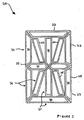
- FIG. 3 An enlarged plan view of a portion of an electronic display according to the invention is illustrated in Figure 3.
- the inner region 60 is formed from an electroluminescent display element 33 and the outer peripheral rim 61 is formed from an electrophoretic display element 34.
- the construction of the whole hybrid display and the electroluminescent display element 33 will be described in more detail with reference to Figure 5.
- the electrophoretic display element 34 comprises millions of tiny microcapsules 36 (only seven microcapsules being shown in the greatly enlarged view of Figure 3).
- each microcapsule 36 contains positively charged white particles 37 and negatively charged black particles 38 suspended in a clear fluid 39 and sandwiched between thin electrode sheets 40, 41 above and below the microcapsules 36.
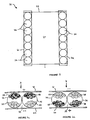
- FIG. 5 An exploded perspective view of the hybrid display is shown in Figure 5. It can be seen that the reflective or electrophoretic display element 34 is disposed on top of the light emissive or electroluminescent display element 33.
- the electrophoretic display element 34 is arranged so that the electroluminescent display element 33 can be seen beneath the electrophoretic display element 34 by a user viewing the display in the direction indicated by arrow X. More specifically, in the illustrated embodiment, groups of the electrophoretic microcapsules 36 are spaced apart with the electroluminescent display element 33 located beneath them leaving the defined space or central region therebetween free to enable information displayed by the electroluminescent display element 33 to be seen between the groups of electrophoretic display elements 34.
- the electoluminescent display element 33 it is possible, in an alternative embodiment, for the electoluminescent display element 33 to be positioned above the electrophoretic display element 34.
- the illustrated arrangement is a preferable embodiment.
- the electrophoretic display element 33 is opaque in the regions occupied by the electrophoretic microcapsules 36.
- the light from the electroluminescent display element 33 is therefore visible in those regions not occupied by the groups of electrophoretic microcapsules 36 and it is not possible to see light emitted from a region of the electroluminescent display element 33 positioned directly beneath the groups of microcapsules 36.
- an electric potential is applied to each of the electrode layers 40,41 of the electrophoretic display element 34 to cause the particles within each microcapsule 36 to move so that the region of the display formed by the electrophoretic display element 34 is either dark or light.
- the hybrid display includes a clear layer 42 located above the electrode sheet 41 to which a UV barrier film or coating 43 is applied.
- a clear or tinted insulating layer 44 is disposed beneath the lower electrode sheet 40 and separates the electrophoretic display element 34 from the electroluminescent display element 33.
- the electroluminescent display element 33 comprises a dielectric 45 coated in phosphor 46 and disposed between a pair of electrodes 47,48 to which an AC voltage may be applied to cause luminescence of the phosphor coating 46 which will be visible beneath the electrophoretic display element 34 as explained above.
- a polyester backing sheet 50 is disposed beneath the rear electrode 48.
- each segment 31 formed by the electrophoretic display element 34 being visible in high ambient light conditions and the peripheral rim of each segment 31 formed by the electroluminescent display element 33 being visible in comparatively dark conditions.
- one display element may be activated independently from the other display element. This may be achieved by providing a switch operable by the user to change the currently operative display. Alternatively, a light sensor may automatically select the best display element to display information to the viewer in dependence on the ambient lighting conditions.
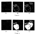
- FIG. 6 An example of how the display would appear to a user is demonstrated by the sequential animated views of a pair of apples shown in Figure 6, which illustrates how the display would be seen in low light or dark conditions when only the light emissive display elements 33 are visible, and Figure 7, which illustrates how the display would be seem in lighted environments when only the reflective display elements 34 are visible.
- the light emissive display elements 33 are located so as to define the outline of the apples to be animated and the reflective display elements 34 form the main body of the apples within the outline (the respective display elements can said to display complimentary images of one another.
- the positioning of the light emissive and reflective display elements 33,34 can be reversed.
- Figure 6a shows how the display appears when no animation is activated i.e. neither the light emissive or reflective display elements 33,34 are operative. In this situation, the display appears completely blank or only a faint outline of the apples that may be animated are visible.
- Figure 6b the outline of the front apple is illuminated. As indicated above, the outline of the apple is formed by the light emissive elements 33 and so is visible in the low light or dark conditions. The body of the apple within the outline appears black because that part is formed by the reflective display elements 34 that are only visible when there is a sufficient level of ambient light.
- Figure 6c shows the same view as Figure 6b, but with the outline of the second apple also now made visible by the light emissive display elements 33.
- Figure 7a corresponds to the view of Figure 6a and shows how the display appears when no animation is activated i.e. neither the light emissive or reflective display elements 33,34 are operative.
- Figure 7b the main body of the apple is visible and appears white.
- the body of the apple is formed from reflective display elements 34 and so this part of the display becomes visible in lighted environments.
- the outline of the apple now appears comparatively black or very faint because the light emissive display elements 33 are not seen easily in well-lighted conditions.
- Figure 7c shows the same view as Figure 7b, but with the body of the second apple also now made visible by the reflective display elements 34.
- the electronic display of the present invention is clearly visible in both light and dark environments due to the use of two different display types, one of which relies on reflection and the other which relies on illumination.
Landscapes
- Physics & Mathematics (AREA)
- General Physics & Mathematics (AREA)
- Engineering & Computer Science (AREA)
- Theoretical Computer Science (AREA)
- Devices For Indicating Variable Information By Combining Individual Elements (AREA)
- Control Of Indicators Other Than Cathode Ray Tubes (AREA)
- Electrochromic Elements, Electrophoresis, Or Variable Reflection Or Absorption Elements (AREA)
- Display Devices Of Pinball Game Machines (AREA)
- Liquid Crystal Substances (AREA)
- Measuring Pulse, Heart Rate, Blood Pressure Or Blood Flow (AREA)
Applications Claiming Priority (2)
| Application Number | Priority Date | Filing Date | Title |
|---|---|---|---|
| GB0211793 | 2002-05-22 | ||
| GB0211793A GB2389696B (en) | 2002-05-22 | 2002-05-22 | Hybrid display |
Publications (3)
| Publication Number | Publication Date |
|---|---|
| EP1365377A2 true EP1365377A2 (de) | 2003-11-26 |
| EP1365377A3 EP1365377A3 (de) | 2005-12-28 |
| EP1365377B1 EP1365377B1 (de) | 2007-11-28 |
Family
ID=9937203
Family Applications (1)
| Application Number | Title | Priority Date | Filing Date |
|---|---|---|---|
| EP03011329A Expired - Lifetime EP1365377B1 (de) | 2002-05-22 | 2003-05-19 | Elektronische Anzeigevorrichtung |
Country Status (5)
| Country | Link |
|---|---|
| US (1) | US7170506B2 (de) |
| EP (1) | EP1365377B1 (de) |
| AT (1) | ATE379828T1 (de) |
| DE (1) | DE60317734T2 (de) |
| GB (1) | GB2389696B (de) |
Cited By (2)
| Publication number | Priority date | Publication date | Assignee | Title |
|---|---|---|---|---|
| FR2999312A1 (fr) * | 2012-12-12 | 2014-06-13 | Thales Sa | Systeme de visualisation comportant un dispositif de visualisation semi-transparent affichant des symboles a contour contraste |
| EP2449455A4 (de) * | 2009-06-30 | 2015-08-05 | Anzeigevorrichtung und entsprechende verfahren |
Families Citing this family (28)
| Publication number | Priority date | Publication date | Assignee | Title |
|---|---|---|---|---|
| US6987603B2 (en) * | 2003-01-31 | 2006-01-17 | E Ink Corporation | Construction of electrophoretic displays |
| TWI290250B (en) * | 2005-01-25 | 2007-11-21 | Ind Tech Res Inst | An emireflective display and method for adjustable display mode |
| TWI326372B (en) * | 2005-08-08 | 2010-06-21 | Ind Tech Res Inst | Emireflective display and method thereof |
| TWI294749B (en) * | 2005-12-29 | 2008-03-11 | Ind Tech Res Inst | Display device and method for fabricating display device |
| TW200732733A (en) * | 2006-02-17 | 2007-09-01 | Ind Tech Res Inst | Hybrid display |
| US8477102B2 (en) * | 2006-03-22 | 2013-07-02 | Eastman Kodak Company | Increasing conductive polymer life by reversing voltage |
| TWI426531B (zh) * | 2006-10-12 | 2014-02-11 | 坎畢歐科技公司 | 以奈米線為主之透明導體及其應用 |
| TW200827828A (en) * | 2006-12-29 | 2008-07-01 | Innolux Display Corp | Liquid crystal display device |
| US8022615B2 (en) * | 2007-08-14 | 2011-09-20 | Motorola Mobility, Inc. | Light generating layer for a reflective display |
| US20100328223A1 (en) * | 2009-06-30 | 2010-12-30 | Nokia Corporation | Apparatus and associated methods |
| US8648772B2 (en) * | 2009-08-20 | 2014-02-11 | Amazon Technologies, Inc. | Amalgamated display comprising dissimilar display devices |
| DE102009038469B4 (de) * | 2009-08-21 | 2015-02-12 | Advanced Display Technology Ag | Anzeigeelement und Verfahren zum Ansteuern eines Anzeigeelementes |
| JP5496344B2 (ja) | 2009-10-14 | 2014-05-21 | ドルビー ラボラトリーズ ライセンシング コーポレイション | バリアブルなフラワーディスプレイのバックライトシステム |
| US9035975B2 (en) | 2009-10-14 | 2015-05-19 | Dolby Laboratories Licensing Corporation | Variable flower display backlight system |
| JP5516173B2 (ja) * | 2009-10-14 | 2014-06-11 | セイコーエプソン株式会社 | 表示シート、表示装置および電子機器 |
| US11568772B2 (en) * | 2010-05-27 | 2023-01-31 | Neville Boston | Method and system for rendering content on the exterior of a vehicle |
| US11467466B2 (en) | 2012-04-20 | 2022-10-11 | E Ink Corporation | Illumination systems for reflective displays |
| US10190743B2 (en) | 2012-04-20 | 2019-01-29 | E Ink Corporation | Illumination systems for reflective displays |
| US9379350B2 (en) | 2012-05-22 | 2016-06-28 | Electronics And Telecommunications Research Institute | Dual mode display apparatus and method of manufacturing the same |
| US9236577B2 (en) | 2012-05-22 | 2016-01-12 | Electronics And Telecommunications Research Institute | Dual-mode display device and method of manufacturing same |
| KR101923725B1 (ko) | 2012-07-12 | 2018-11-29 | 한국전자통신연구원 | 듀얼 모드 디스플레이 장치 및 그의 제조방법 |
| KR101906591B1 (ko) | 2012-12-12 | 2018-10-12 | 한국전자통신연구원 | 자발광형 및 반사형 소자를 포함하는 이중모드 화소 및 이를 이용한 이중모드 디스플레이 |
| KR102050243B1 (ko) | 2013-12-02 | 2019-11-29 | 한국전자통신연구원 | 자발광형 소자 및 반사형 소자를 포함하는 이중모드 화소 및 이를 이용한 이중모드 디스플레이 |
| KR102038532B1 (ko) | 2014-01-28 | 2019-11-26 | 한국전자통신연구원 | 표시 장치 및 이를 제조하는 방법 |
| CN103955099B (zh) * | 2014-04-28 | 2016-09-07 | 京东方科技集团股份有限公司 | 彩膜基板及其制作方法和显示装置 |
| KR102220553B1 (ko) | 2015-03-10 | 2021-02-26 | 한국전자통신연구원 | 표시 패널 및 그것을 포함하는 표시 장치 |
| TWI840104B (zh) * | 2016-08-29 | 2024-04-21 | 日商半導體能源研究所股份有限公司 | 顯示裝置及控制程式 |
| WO2020122917A1 (en) | 2018-12-13 | 2020-06-18 | E Ink Corporation | Illumination systems for reflective displays |
Family Cites Families (10)
| Publication number | Priority date | Publication date | Assignee | Title |
|---|---|---|---|---|
| US4163332B2 (en) * | 1976-10-05 | 1995-09-05 | Unisplay Sa | Matrix display device |
| JPS5810481U (ja) * | 1981-07-10 | 1983-01-22 | シャープ株式会社 | 液晶表示装置 |
| US6091194A (en) * | 1995-11-22 | 2000-07-18 | Motorola, Inc. | Active matrix display |
| US6195140B1 (en) * | 1997-07-28 | 2001-02-27 | Sharp Kabushiki Kaisha | Liquid crystal display in which at least one pixel includes both a transmissive region and a reflective region |
| US5808711A (en) * | 1997-08-22 | 1998-09-15 | Motorola, Inc. | Transparent or reflective liquid crystal display assembly with electrochromic and cholesteric layer |
| AU3190499A (en) * | 1998-03-18 | 1999-10-11 | E-Ink Corporation | Electrophoretic displays and systems for addressing such displays |
| US6144359A (en) * | 1998-03-30 | 2000-11-07 | Rockwell Science Center | Liquid crystal displays utilizing polymer dispersed liquid crystal devices for enhanced performance and reduced power |
| US6842170B1 (en) * | 1999-03-17 | 2005-01-11 | Motorola, Inc. | Display with aligned optical shutter and backlight cells applicable for use with a touchscreen |
| JP2002014343A (ja) * | 2000-04-26 | 2002-01-18 | Nec Corp | 液晶表示装置、発光素子、液晶表示装置の製造方法 |
| US20030098856A1 (en) * | 2001-11-28 | 2003-05-29 | Zili Li | Selective ambient light attenuating device and associated emissive display |
-
2002
- 2002-05-22 GB GB0211793A patent/GB2389696B/en not_active Expired - Fee Related
-
2003
- 2003-05-19 DE DE60317734T patent/DE60317734T2/de not_active Expired - Lifetime
- 2003-05-19 EP EP03011329A patent/EP1365377B1/de not_active Expired - Lifetime
- 2003-05-19 AT AT03011329T patent/ATE379828T1/de not_active IP Right Cessation
- 2003-05-20 US US10/442,808 patent/US7170506B2/en not_active Expired - Lifetime
Cited By (3)
| Publication number | Priority date | Publication date | Assignee | Title |
|---|---|---|---|---|
| EP2449455A4 (de) * | 2009-06-30 | 2015-08-05 | Anzeigevorrichtung und entsprechende verfahren | |
| FR2999312A1 (fr) * | 2012-12-12 | 2014-06-13 | Thales Sa | Systeme de visualisation comportant un dispositif de visualisation semi-transparent affichant des symboles a contour contraste |
| US9245498B2 (en) | 2012-12-12 | 2016-01-26 | Thales | Display system having a semitransparent display device displaying symbols with a contrasted outline |
Also Published As
| Publication number | Publication date |
|---|---|
| EP1365377B1 (de) | 2007-11-28 |
| EP1365377A3 (de) | 2005-12-28 |
| GB2389696A (en) | 2003-12-17 |
| GB0211793D0 (en) | 2002-07-03 |
| GB2389696B (en) | 2005-06-01 |
| DE60317734D1 (de) | 2008-01-10 |
| DE60317734T2 (de) | 2008-04-10 |
| ATE379828T1 (de) | 2007-12-15 |
| US20030218595A1 (en) | 2003-11-27 |
| US7170506B2 (en) | 2007-01-30 |
Similar Documents
| Publication | Publication Date | Title |
|---|---|---|
| EP1365377B1 (de) | Elektronische Anzeigevorrichtung | |
| US9245492B2 (en) | Dual screen display for mobile computing device | |
| CN101393359B (zh) | 具有多个光闸的光开关 | |
| KR100358668B1 (ko) | 터치스크린과 함께 이용 가능한 정렬된 광학 셔터 및 배경조명 셀을 구비한 표시 장치 | |
| EP0963668B1 (de) | Elektronisches gerät mit einer anzeige die von gegenüberliegenden seiten sichtbar ist | |
| WO2008137290A1 (en) | Dual-sided electrophoretic display | |
| US8369890B2 (en) | Mobile electronic device with an illuminated static display | |
| US8049840B2 (en) | Double-sided display apparatus | |
| US20060256421A1 (en) | Electrophoretic display device | |
| US20100026933A1 (en) | Secondary display using pdlc | |
| JP4211255B2 (ja) | 電気泳動表示装置および電子機器 | |
| US20110175817A1 (en) | Mobile terminal | |
| KR20100022437A (ko) | 분할 전극을 갖춘 액정 디스플레이 | |
| WO2006080277A1 (ja) | 表示装置 | |
| JP2006004354A (ja) | 入力パネル及びこれを用いた入力装置 | |
| KR200205036Y1 (ko) | 터치스크린을 이용한 판넬형 멀티스위치 | |
| KR200199486Y1 (ko) | 액정표시장치 | |
| US20110043370A1 (en) | Animated logo for a portable computer | |
| JP2011061340A (ja) | 折畳型携帯端末装置 | |
| JPS61278926A (ja) | 表示兼入力装置 | |
| WO2004066067A2 (en) | Multi-layer laminated user interface | |
| JPH0438385Y2 (de) | ||
| JP2000075809A (ja) | 表示装置 | |
| KR20010099552A (ko) | 휴대용 표시 장치 | |
| JPS61278924A (ja) | 表示兼入力装置 |
Legal Events
| Date | Code | Title | Description |
|---|---|---|---|
| PUAI | Public reference made under article 153(3) epc to a published international application that has entered the european phase |
Free format text: ORIGINAL CODE: 0009012 |
|
| AK | Designated contracting states |
Kind code of ref document: A2 Designated state(s): AT BE BG CH CY CZ DE DK EE ES FI FR GB GR HU IE IT LI LU MC NL PT RO SE SI SK TR |
|
| AX | Request for extension of the european patent |
Extension state: AL LT LV MK |
|
| PUAL | Search report despatched |
Free format text: ORIGINAL CODE: 0009013 |
|
| AK | Designated contracting states |
Kind code of ref document: A3 Designated state(s): AT BE BG CH CY CZ DE DK EE ES FI FR GB GR HU IE IT LI LU MC NL PT RO SE SI SK TR |
|
| AX | Request for extension of the european patent |
Extension state: AL LT LV MK |
|
| 17P | Request for examination filed |
Effective date: 20060628 |
|
| AKX | Designation fees paid |
Designated state(s): AT BE BG CH CY CZ DE DK EE ES FI FR GB GR HU IE IT LI LU MC NL PT RO SE SI SK TR |
|
| AXX | Extension fees paid |
Extension state: LT Payment date: 20060628 Extension state: AL Payment date: 20060628 Extension state: MK Payment date: 20060628 Extension state: LV Payment date: 20060628 |
|
| 17Q | First examination report despatched |
Effective date: 20060830 |
|
| GRAP | Despatch of communication of intention to grant a patent |
Free format text: ORIGINAL CODE: EPIDOSNIGR1 |
|
| GRAS | Grant fee paid |
Free format text: ORIGINAL CODE: EPIDOSNIGR3 |
|
| GRAA | (expected) grant |
Free format text: ORIGINAL CODE: 0009210 |
|
| AK | Designated contracting states |
Kind code of ref document: B1 Designated state(s): AT BE BG CH CY CZ DE DK EE ES FI FR GB GR HU IE IT LI LU MC NL PT RO SE SI SK TR |
|
| AX | Request for extension of the european patent |
Extension state: AL LT LV MK |
|
| REG | Reference to a national code |
Ref country code: IE Ref legal event code: FG4D |
|
| REG | Reference to a national code |
Ref country code: CH Ref legal event code: EP |
|
| REF | Corresponds to: |
Ref document number: 60317734 Country of ref document: DE Date of ref document: 20080110 Kind code of ref document: P |
|
| PG25 | Lapsed in a contracting state [announced via postgrant information from national office to epo] |
Ref country code: SE Free format text: LAPSE BECAUSE OF FAILURE TO SUBMIT A TRANSLATION OF THE DESCRIPTION OR TO PAY THE FEE WITHIN THE PRESCRIBED TIME-LIMIT Effective date: 20080228 Ref country code: ES Free format text: LAPSE BECAUSE OF FAILURE TO SUBMIT A TRANSLATION OF THE DESCRIPTION OR TO PAY THE FEE WITHIN THE PRESCRIBED TIME-LIMIT Effective date: 20080311 Ref country code: LI Free format text: LAPSE BECAUSE OF FAILURE TO SUBMIT A TRANSLATION OF THE DESCRIPTION OR TO PAY THE FEE WITHIN THE PRESCRIBED TIME-LIMIT Effective date: 20071128 Ref country code: CH Free format text: LAPSE BECAUSE OF FAILURE TO SUBMIT A TRANSLATION OF THE DESCRIPTION OR TO PAY THE FEE WITHIN THE PRESCRIBED TIME-LIMIT Effective date: 20071128 |
|
| ET | Fr: translation filed | ||
| LTIE | Lt: invalidation of european patent or patent extension |
Effective date: 20071128 |
|
| PG25 | Lapsed in a contracting state [announced via postgrant information from national office to epo] |
Ref country code: SI Free format text: LAPSE BECAUSE OF FAILURE TO SUBMIT A TRANSLATION OF THE DESCRIPTION OR TO PAY THE FEE WITHIN THE PRESCRIBED TIME-LIMIT Effective date: 20071128 Ref country code: BG Free format text: LAPSE BECAUSE OF FAILURE TO SUBMIT A TRANSLATION OF THE DESCRIPTION OR TO PAY THE FEE WITHIN THE PRESCRIBED TIME-LIMIT Effective date: 20080228 |
|
| REG | Reference to a national code |
Ref country code: CH Ref legal event code: PL |
|
| PG25 | Lapsed in a contracting state [announced via postgrant information from national office to epo] |
Ref country code: AT Free format text: LAPSE BECAUSE OF FAILURE TO SUBMIT A TRANSLATION OF THE DESCRIPTION OR TO PAY THE FEE WITHIN THE PRESCRIBED TIME-LIMIT Effective date: 20071128 |
|
| PG25 | Lapsed in a contracting state [announced via postgrant information from national office to epo] |
Ref country code: CZ Free format text: LAPSE BECAUSE OF FAILURE TO SUBMIT A TRANSLATION OF THE DESCRIPTION OR TO PAY THE FEE WITHIN THE PRESCRIBED TIME-LIMIT Effective date: 20071128 Ref country code: DK Free format text: LAPSE BECAUSE OF FAILURE TO SUBMIT A TRANSLATION OF THE DESCRIPTION OR TO PAY THE FEE WITHIN THE PRESCRIBED TIME-LIMIT Effective date: 20071128 |
|
| PG25 | Lapsed in a contracting state [announced via postgrant information from national office to epo] |
Ref country code: RO Free format text: LAPSE BECAUSE OF FAILURE TO SUBMIT A TRANSLATION OF THE DESCRIPTION OR TO PAY THE FEE WITHIN THE PRESCRIBED TIME-LIMIT Effective date: 20071128 Ref country code: BE Free format text: LAPSE BECAUSE OF FAILURE TO SUBMIT A TRANSLATION OF THE DESCRIPTION OR TO PAY THE FEE WITHIN THE PRESCRIBED TIME-LIMIT Effective date: 20071128 Ref country code: SK Free format text: LAPSE BECAUSE OF FAILURE TO SUBMIT A TRANSLATION OF THE DESCRIPTION OR TO PAY THE FEE WITHIN THE PRESCRIBED TIME-LIMIT Effective date: 20071128 |
|
| PG25 | Lapsed in a contracting state [announced via postgrant information from national office to epo] |
Ref country code: PT Free format text: LAPSE BECAUSE OF FAILURE TO SUBMIT A TRANSLATION OF THE DESCRIPTION OR TO PAY THE FEE WITHIN THE PRESCRIBED TIME-LIMIT Effective date: 20080428 |
|
| PLBE | No opposition filed within time limit |
Free format text: ORIGINAL CODE: 0009261 |
|
| STAA | Information on the status of an ep patent application or granted ep patent |
Free format text: STATUS: NO OPPOSITION FILED WITHIN TIME LIMIT |
|
| 26N | No opposition filed |
Effective date: 20080829 |
|
| PG25 | Lapsed in a contracting state [announced via postgrant information from national office to epo] |
Ref country code: MC Free format text: LAPSE BECAUSE OF NON-PAYMENT OF DUE FEES Effective date: 20080531 |
|
| PG25 | Lapsed in a contracting state [announced via postgrant information from national office to epo] |
Ref country code: GR Free format text: LAPSE BECAUSE OF FAILURE TO SUBMIT A TRANSLATION OF THE DESCRIPTION OR TO PAY THE FEE WITHIN THE PRESCRIBED TIME-LIMIT Effective date: 20080229 |
|
| PG25 | Lapsed in a contracting state [announced via postgrant information from national office to epo] |
Ref country code: EE Free format text: LAPSE BECAUSE OF FAILURE TO SUBMIT A TRANSLATION OF THE DESCRIPTION OR TO PAY THE FEE WITHIN THE PRESCRIBED TIME-LIMIT Effective date: 20071128 Ref country code: IE Free format text: LAPSE BECAUSE OF NON-PAYMENT OF DUE FEES Effective date: 20080519 |
|
| PG25 | Lapsed in a contracting state [announced via postgrant information from national office to epo] |
Ref country code: CY Free format text: LAPSE BECAUSE OF FAILURE TO SUBMIT A TRANSLATION OF THE DESCRIPTION OR TO PAY THE FEE WITHIN THE PRESCRIBED TIME-LIMIT Effective date: 20071128 |
|
| PG25 | Lapsed in a contracting state [announced via postgrant information from national office to epo] |
Ref country code: LU Free format text: LAPSE BECAUSE OF NON-PAYMENT OF DUE FEES Effective date: 20080519 Ref country code: HU Free format text: LAPSE BECAUSE OF FAILURE TO SUBMIT A TRANSLATION OF THE DESCRIPTION OR TO PAY THE FEE WITHIN THE PRESCRIBED TIME-LIMIT Effective date: 20080529 |
|
| PG25 | Lapsed in a contracting state [announced via postgrant information from national office to epo] |
Ref country code: TR Free format text: LAPSE BECAUSE OF FAILURE TO SUBMIT A TRANSLATION OF THE DESCRIPTION OR TO PAY THE FEE WITHIN THE PRESCRIBED TIME-LIMIT Effective date: 20071128 |
|
| PG25 | Lapsed in a contracting state [announced via postgrant information from national office to epo] |
Ref country code: IT Free format text: LAPSE BECAUSE OF NON-PAYMENT OF DUE FEES Effective date: 20080531 |
|
| PGFP | Annual fee paid to national office [announced via postgrant information from national office to epo] |
Ref country code: FI Payment date: 20150512 Year of fee payment: 13 |
|
| REG | Reference to a national code |
Ref country code: GB Ref legal event code: 732E Free format text: REGISTERED BETWEEN 20150910 AND 20150916 |
|
| REG | Reference to a national code |
Ref country code: DE Ref legal event code: R082 Ref document number: 60317734 Country of ref document: DE Representative=s name: BECKER, KURIG, STRAUS, DE Ref country code: DE Ref legal event code: R081 Ref document number: 60317734 Country of ref document: DE Owner name: NOKIA TECHNOLOGIES OY, FI Free format text: FORMER OWNER: NOKIA CORP., 02610 ESPOO, FI |
|
| REG | Reference to a national code |
Ref country code: FR Ref legal event code: PLFP Year of fee payment: 14 |
|
| REG | Reference to a national code |
Ref country code: NL Ref legal event code: PD Owner name: NOKIA TECHNOLOGIES OY; FI Free format text: DETAILS ASSIGNMENT: VERANDERING VAN EIGENAAR(S), OVERDRACHT; FORMER OWNER NAME: NOKIA CORPORATION Effective date: 20151111 |
|
| PG25 | Lapsed in a contracting state [announced via postgrant information from national office to epo] |
Ref country code: FI Free format text: LAPSE BECAUSE OF NON-PAYMENT OF DUE FEES Effective date: 20160519 |
|
| REG | Reference to a national code |
Ref country code: FR Ref legal event code: TP Owner name: NOKIA TECHNOLOGIES OY, FI Effective date: 20170109 |
|
| REG | Reference to a national code |
Ref country code: FR Ref legal event code: PLFP Year of fee payment: 15 |
|
| REG | Reference to a national code |
Ref country code: FR Ref legal event code: PLFP Year of fee payment: 16 |
|
| PGFP | Annual fee paid to national office [announced via postgrant information from national office to epo] |
Ref country code: GB Payment date: 20180516 Year of fee payment: 16 |
|
| PGFP | Annual fee paid to national office [announced via postgrant information from national office to epo] |
Ref country code: NL Payment date: 20190515 Year of fee payment: 17 |
|
| PGFP | Annual fee paid to national office [announced via postgrant information from national office to epo] |
Ref country code: DE Payment date: 20190508 Year of fee payment: 17 |
|
| PGFP | Annual fee paid to national office [announced via postgrant information from national office to epo] |
Ref country code: FR Payment date: 20190410 Year of fee payment: 17 |
|
| GBPC | Gb: european patent ceased through non-payment of renewal fee |
Effective date: 20190519 |
|
| PG25 | Lapsed in a contracting state [announced via postgrant information from national office to epo] |
Ref country code: GB Free format text: LAPSE BECAUSE OF NON-PAYMENT OF DUE FEES Effective date: 20190519 |
|
| REG | Reference to a national code |
Ref country code: DE Ref legal event code: R119 Ref document number: 60317734 Country of ref document: DE |
|
| REG | Reference to a national code |
Ref country code: NL Ref legal event code: MM Effective date: 20200601 |
|
| PG25 | Lapsed in a contracting state [announced via postgrant information from national office to epo] |
Ref country code: NL Free format text: LAPSE BECAUSE OF NON-PAYMENT OF DUE FEES Effective date: 20200601 |
|
| PG25 | Lapsed in a contracting state [announced via postgrant information from national office to epo] |
Ref country code: FR Free format text: LAPSE BECAUSE OF NON-PAYMENT OF DUE FEES Effective date: 20200531 |
|
| PG25 | Lapsed in a contracting state [announced via postgrant information from national office to epo] |
Ref country code: DE Free format text: LAPSE BECAUSE OF NON-PAYMENT OF DUE FEES Effective date: 20201201 |