EP1365400B1 - Einstellung der Rotationsgeschwindigkeit eines rotierenden Plattenspeichers - Google Patents
Einstellung der Rotationsgeschwindigkeit eines rotierenden Plattenspeichers Download PDFInfo
- Publication number
- EP1365400B1 EP1365400B1 EP02010142A EP02010142A EP1365400B1 EP 1365400 B1 EP1365400 B1 EP 1365400B1 EP 02010142 A EP02010142 A EP 02010142A EP 02010142 A EP02010142 A EP 02010142A EP 1365400 B1 EP1365400 B1 EP 1365400B1
- Authority
- EP
- European Patent Office
- Prior art keywords
- rotation speed
- disk drive
- interface
- disk
- disk memory
- Prior art date
- Legal status (The legal status is an assumption and is not a legal conclusion. Google has not performed a legal analysis and makes no representation as to the accuracy of the status listed.)
- Expired - Lifetime
Links
- 230000015654 memory Effects 0.000 title claims description 68
- 238000000034 method Methods 0.000 claims description 11
- 230000003287 optical effect Effects 0.000 claims description 3
- 230000005540 biological transmission Effects 0.000 description 9
- 238000004891 communication Methods 0.000 description 4
- 230000006870 function Effects 0.000 description 3
- 238000012546 transfer Methods 0.000 description 3
- 238000013459 approach Methods 0.000 description 2
- 238000004364 calculation method Methods 0.000 description 2
- 230000000694 effects Effects 0.000 description 2
- 238000012545 processing Methods 0.000 description 2
- 230000001133 acceleration Effects 0.000 description 1
- 230000003139 buffering effect Effects 0.000 description 1
- 230000003247 decreasing effect Effects 0.000 description 1
- 230000001419 dependent effect Effects 0.000 description 1
- 238000013461 design Methods 0.000 description 1
- 238000009826 distribution Methods 0.000 description 1
- 238000005265 energy consumption Methods 0.000 description 1
- 239000000945 filler Substances 0.000 description 1
- 230000002093 peripheral effect Effects 0.000 description 1
- 230000001360 synchronised effect Effects 0.000 description 1
Images


Classifications
-
- G—PHYSICS
- G11—INFORMATION STORAGE
- G11B—INFORMATION STORAGE BASED ON RELATIVE MOVEMENT BETWEEN RECORD CARRIER AND TRANSDUCER
- G11B19/00—Driving, starting, stopping record carriers not specifically of filamentary or web form, or of supports therefor; Control thereof; Control of operating function ; Driving both disc and head
- G11B19/20—Driving; Starting; Stopping; Control thereof
- G11B19/26—Speed-changing arrangements; Reversing arrangements; Drive-transfer means therefor
Definitions
- the invention relates to a device comprising a disk drive for rotating a disk memory and at least two interfaces enabling a data flow between a disk memory rotated by the disk drive and at least one other module.
- the invention relates equally to a method for setting the rotation speed of a disk drive of such a device.
- rotating disk based memories like hard disk drives (HDD) or optical disks are employed for storing data.
- Data can be written into such a disk memory or read from such a disk memory while it is rotated by a disk drive of some device.
- Data that is to be stored in the rotating disk memory can be provided by some module internal or external to the device. Equally, a module internal or external to the device might require data that is stored in the rotating disk memory.
- modules can be connected to the rotating disk memory via an interface enabling a corresponding data flow.
- a buffer is required, in order to be able to store data read from the rotating disk memory with a data rate exceeding the data rate supported by the slower interfaces.
- This buffer is usually realized as a non-volatile buffer.
- Document US 4,943,907 presents a speed control arrangement for a computer's floppy controller and a peripheral drive having plurality of operating speeds.
- the provided facilities cause the two devices automatically to operate at the highest data rate common to both.
- Document EP 1 168 326 A2 proposes reading information from an information medium that is rotated, and determining a rotation velocity of the information medium on the basis of a data transfer rate based on a specification of a read request.
- a device comprising a disk drive for rotating a disk memory and with at least two interfaces enabling a data flow between a disk memory rotated by the disk drive and at least one other module.
- the proposed device further comprises means for setting the rotation speed of the disk drive based on an indication of the data rate supported by an interface of the device, which interface is currently to be employed for enabling a data flow between the rotating disk memory and at least one other module.
- the object of the invention is reached with a method for setting the rotation speed of a disk drive of such a device.
- the proposed method comprises as a first step determining a rotation speed for the disk drive based on an indication of the data rate supported by an interface of the device, which interface is currently to be employed for enabling a data flow between the disk memory and at least one other module.
- the rotation speed of the disk drive is then set to the determined rotation speed.
- the invention proceeds from the consideration that the effective data rate of the data read from or written to a rotating disk memory relates to the rotation speed of the disk memory, and that therefore, it is possible to achieve an optimal co-operation between a rotating disk memory and an interface, if the respective rotation speed is adapted to the capabilities of the employed interface.
- the effective data rate of the disk memory can be adjusted in particular such that it is always close to the effective data rate of the currently employed interface.
- the invention therefore eliminates the need for a non-volatile buffer. This allows to remove one component from the system and thus to reduce cost and size of the device. A volatile cache will be sufficient for handling irregularities in the data traffic.
- the same software and hardware for controlling the disk memory can be used for devices comprising only a slow interface, for devices comprising only a fast interface and for devices comprising slow and fast interfaces, since in each case the rotation speed is adjusted automatically to the optimum value for the respectively used interface.
- the disk memory will be operated at two speeds, a high speed resulting in a high data rate for the fast interface, in order to improve the usability, and a low speed resulting in a low data rate for the slow interface, in order to decrease the power consumption.
- the disk memory that is rotated by the disk drive of the device can be for example a hard disk drive or an optical disk.
- At least one interface of the device can be a wired interface or a wireless interface.
- a wired interface e.g. a USB (Universal Serial Bus) interface
- USB Universal Serial Bus
- a wireless interface like a Bluetooth TM interface.
- USB and Bluetooth TM are only exemplary interfaces. The invention can equally be employed with any other interface.
- the indication of the data rate supported by the respective interface can be provided to the means for adjusting the rotation speed, e.g. by an indication of the type of the interface for which the supported data rate is known.
- the means for adapting the rotation speed of the disk memory may comprise in particular a servo driver controlling the rotation speed of the disk drive.
- the rotation speed of the disk memory is varied by a servo driver according to a rotation profile which is either defined by software or hard-coded into the servo driver.
- the rotation profile associates a respective indication of the data rate supported by an interface to a respective rotation speed to be employed for a disk memory.
- the software forwards the determined rotation speed to the servo driver for adjusting the rotation speed of the disk drive.
- all possible applications for which a data flow may be desired are divided into a plurality of classes, based on the data-rate requirements of the respective application.
- the class of the respective application is then taken into account in addition, when determining the rotation speed.
- the applications are divided into 2-3 classes, and the disk speed is set accordingly to one of 2-3 different values depending on the class of the particular running application.
- This embodiment of the invention can be implemented in a variety of ways.
- the required class information is included as an extra field in a file allocation table.
- a mirror copy of a file allocation table is created in a non-volatile memory, which memory holds the normal file allocation table data in addition to a field associating the files to a respective class.
- the mirror file allocation table is then used to access the data.
- the mirror file allocation table and the actual file allocation table have to be kept synchronized.
- the required class information is derived from file attributes, when the system receives the command to access a file, e.g. the file extension.
- the other module or modules connected to the disk memory via an interface can either be comprised in a device according to the invention, or be external to such a device.
- the device and the method according to the invention may support a one-to-one connection, i.e. a connection between the device and one other module, or a one-to-many connection, i.e. a connection between the device and several other modules. It is an advantage of a device and a method realizing a one-to-one connection that they will be significantly simpler.
- the device can further be a stand-alone system or part of a larger system, like a mobile phone. In the latter case, a connection possibility for other components of the system to the device will usually be required, in order to enable communications within the system.
- a queue control algorithm is used to optimize the usage of the disk memory. For example, it would be disadvantageous to switch rotation speeds quickly, since this requires much energy. Therefore, it is proposed to employ a queue control algorithm for grouping those operations together which require the same speed. This should be balanced against the user wait times, in which such a grouping can result. Another approach could be to arrange data transfers concerning the same module in a consecutive order in the queue.
- the queue control algorithm can also be simplified for a device comprising a plurality of interfaces, in case there is a restriction that only one interface can operate at a time. Such a restriction would avoid the need to group transmissions requiring the same speed together.
- the most flexible queuing algorithm has thus three modes, a BT-only mode, an USB-only mode and a joint BT and USB mode. All the other software can be shared in the three modes.
- the device according to the invention can be any device that enables the use of a rotating disk memory.
- the invention is of a particular advantage for handheld devices like mobile terminals.
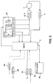
- Figure 1 shows a system comprising an embodiment of a device according to the invention and two modules connected to the device.
- the device can be for example a mobile terminal of a first user, and the modules can be mobile terminals of other users.
- the device comprises a disk drive 1 for rotating a rotating disk memory.
- the disk drive 1 is controlled by servo drivers 2, arm drivers 3 and R/W (read/write) drivers 4.
- the servo drivers 2 control the rotation speed of the disk drive 1, while the arm drivers control read/write heads used for reading data from and writing data to a rotating disk memory.
- the R/W drivers 4 control the actual reading of data from a disk memory and writing data to a disk memory.
- Servo drivers 2, arm drivers 3 and R/W drivers 4 are further connected to system and EM chip or chips 5.
- the operation mode of the connection between the servo drivers 2 and the system and EM chip 5 can be "sleep", "idle”, “seek”, or "rotating".
- the operation mode of the connection between the arm drivers 3 and the system and EM chip 5 can be “sleep”, “idle” or “seeking”.
- the operation mode of the connection between the R/W drivers 4 and the system and EM chip 5 can be “sleep”, “idle” or "R/W”.
- the system and EM chip 5 comprises an energy management (EM) part 6, a microcontroller unit (MCU) 7, a random access memory (RAM) 8 and a nonvolatile memory (NVM) 9, e.g. a flash memory.
- EM energy management
- MCU microcontroller unit
- RAM random access memory
- NVM nonvolatile memory
- the EM part 6 provides a wireless interface for connecting modules supporting Bluetooth TM to the device and a USB interface for connecting modules via USB to the device.
- a Bluetooth TM component 10 is connected to the device via a Bluetooth TM driver 11 included in the Bluetooth TM component 10.
- a second module 12 comprising a USB slot is connected to the device via a USB driver 13 included in the second module 12.
- the operation mode of the connection between the EM part 6 and the Bluetooth TM component 10 can be "sleep", “monitor” or "RX/TX" (receiving/transmitting). The same operation modes are available for the connection between the EM part 6 and the USB module 12.
- the MCU 7 constitutes processing means controlling the data flow between a disk memory rotated by the disk drive 1 and modules 10, 12 connected to the system and EM chip 5 via the Bluetooth TM interface or the USB interface.
- the system and EM chip 5 is moreover connected to a non-volatile buffer 14, which is depicted in figure 1 with dotted lines. Also the connection of the buffer 14 to the system and EM chip 5 is depicted with a dotted line. The dotted lines indicate that the buffer 14 is either extremely small or even missing.
- the operation mode of the connection between the system and EM chip 5 and the buffer 14, if present, can be "sleep" or "ready".
- the system and EM chip 5 is connected for their power supply to a battery 15.
- the operation mode of this connection can be “off”, “sleep” or “full power”.
- the battery 15 can be removable or fixed to the device.
- the battery 15 can be connected to an external charger 16 for recharging the battery 15.
- the operation mode of the connection between the battery 15 and the charger 16 can thus be either “off” or “charging”.
- the device is a mobile terminal as suggested above, additional components of the mobile terminal preferably connect to the systems and EM chips 5 of the device for enabling communications within the mobile terminal. Such a connectivity is not required, in case the device is a stand-alone device provided exclusively for an access to the disk drive 1.
- Figures 2 and 3 relate to the operation of a device comprising multiple interfaces. It will be assumed in the following that this device corresponds to the embodiment of figure 1.
- Figure 2 illustrates the reading of data from a disk memory and figure 3 the writing of data into a disk memory.
- the depicted components and connections are identical in figures 2 and 3. However, different inactive or waiting connections are indicated in both figures with different dotted lines.
- the device comprises a Bluetooth TM interface with a receiving unit BT RX 21 and a transmitting unit BT RX 22 and moreover a wired USB interface with a receiving unit USB RX 24 and a transmitting unit USB TX 25. Both interfaces are provided by the EM part 6 of the system and EM chip 5 in figure 1.
- the different receiving and transmitting units 21, 24 and 22, 25 are connected to the MCU 7 of the system and EM chip 5 of figure 1.
- the MCU 7 is used for controlling the traffic between a disk memory and the different interfaces.
- a non-volatile memory 26 constituting a file system is equally connected to the MCU 7.
- the memory 36 can be part of the RAM 8 or the NVM 9 in figure 1 and comprises a file system.
- the file system includes a file system table which constitutes basically a file allocation table (FAT) which enables the device to communicate with the disk drive 1.
- FAT file allocation table
- An output of the MCU 7 is connected to a queue 23. Outputs of the queue 23 are connected to the MCU 7 and to servo and arm drivers 2, 3 controlling the disk drive 1. The disk memory rotated by the disk drive 1 is further connected via an R/W driver 4 to the MCU 7.
- the-maximum bandwidth is reserved for the data-transmitting route to one module, while the other modules are allowed to use only enough bandwidth to transmit read/write commands. This is one of the key factors causing an overhead in the transmissions via the air interface. Since the overhead may not be exactly constant, it may further be necessary to be able to vary the rotation speed a little bit also for a given interface.
- the device is a mobile phone as suggested above, additional components of the mobile phone may be connected to the system and EM chips 5 of figure 1 for required communications specifically via the file system 26.
- the MCU checks with the file system table 26, from which place in the disk memory requested data has to be read, or to which place in the disk memory data provided by a module should be written.
- information is associated to each read/write command received from connected modules.
- the information comprises an indication of the type of the respectively used interface, an identification of the respective module in multiuser protocols, an R/W flag, an indication of where to start reading or writing and, optionally, an indication of where to stop reading or writing in the disk memory.
- the R/W flag indicates whether the command is a read command, identified in the figure by an "R”, or a write command, identified in the figure by a "W". Since only one module at a time can be connected to the device via the USB interface, an identification of such a module is not required.
- This information is provided by the MCU 7 according to commands received via one of the interfaces and according to the information retrieved from the file system table 26.
- the respective information that was first provided to the queue 23 is also first retrieved from the queue 23.
- the currently retrieved information indicates that the concerned interface is a Bluetooth TM interface "BT", that the information relates to a module with an identification number "2", and that data is to be read “R” from a disk memory from place "AA00" to place “AAFF”.
- the retrieved indication of the type of the interface and the identification of the module is transmitted to the MCU 7.
- the indication of the type of the interface is also provided together with the R/W flag and the start and stop information to the servo and arm drivers 2, 3.
- the servo drivers 2 translate the received indication of the type of the concerned interface to an associated rotation speed, i.e. to a rotation speed matched to the data rate supported by the Bluetooth TM interface. This speed is lower than the rotation speed associated to the USB interface.
- the servo driver 2 may comprise a hard-coded rotation profile defining corresponding relations.
- the servo and arm drivers 2, 3 control the rotation speed of the disk drive 1 and the position of the read/write heads in accordance with the determined rotation speed.
- the R/W driver 4 controls a reading of data with a corresponding data rate from place "AA00" to place "AAFF" from a disk memory rotated by the disk drive 1 and provides the read data to the MCU 7.
- the MCU 7 With the indication of the concerned type of interface and of the concerned module, the MCU 7 is able to correctly initiate a transmission of the received data stream to module 2 via the transmission unit BT TX 22 of the Bluetooth TM interface. Since the data rate with which the data is received from the disk memory corresponds basically to the data rate supported by the Bluetooth TM interface, a further storing of the read data is not required.
- the next set of information is retrieved from the queue 23.
- This information indicates that the concerned interface is again a Bluetooth TM interface "BT" and that the information relates again to a module with an identification number "2". In this case, however, data that will be provided by module 2 is to be written "W" into the disk memory beginning at place "BBBB”.
- the indication of the type of the interface and the identification of the module is transmitted again to the MCU 7. Further, the indication of the type of the interface is provided together with the R/W flag and the start information to the servo and drivers 2, 3.
- the servo drivers 2 translate the received indication of the type of the concerned interface again to an associated rotation speed, as described with reference to figure 2.
- the MCU 7 receives data from module 2 via the BT RX 21 in accordance with the information received from the queue 23 and provides the data to the R/W driver 4.
- the servo and arm drivers 2, 3 control meanwhile the disk drive 1 in accordance with the determined rotation speed.
- the R/W driver 4 controls a writing of the received data into a disk memory rotated by the disk drive 1 beginning at place "BBBB" with a data rate corresponding to the rotation speed set by the servo driver 2.
- the rotation speed of the disk drive 1 is always set such that the effective data rate for reading data from or writing data to a rotating disk memory is matched to the data rate supported by the currently employed interface.
- the maximum data rate B in bit/s on the air interface is known.
- the maximum data rate of a disk memory is much higher, but for a wireless transmission as for Bluetooth TM , its effective data rate BD is set according to the invention close to B. More exactly, it is set to k*B, where k is slightly larger than 1 to accommodate overhead in the Bluetooth TM interface. It is to be noted that k will be larger for one-to-many protocols than for one-to-one protocols, since the multiuser protocol needs more overheads.
- the overhead value k may not be exactly constant even for a given interface. It may vary for example with the number of attached modules in a Bluetooth TM -based system. If possible, this should be avoided in the air interface by always using the smallest bandwidth for data transmission, even if the overhead is not needed.
- k could be recalculated for example once a second. If the value of k has changed appreciably, then the rotation speed can be changed accordingly. However, by default such changes should be avoided, since acceleration and deceleration of the disk require the maximum amounts of energy.
- the value of k can also be set to the average expected value, but this requires a larger buffer, since at times the HDD may transmit more bits than the air interface can transmit.
- the data rate of the air interface is B bit/s
Landscapes
- Signal Processing For Digital Recording And Reproducing (AREA)
Claims (14)
- Vorrichtung, die Folgendes umfasst:- ein Plattenlaufwerk (1) zum Rotieren eines Plattenspeichers;- zumindest zwei Schnittstellen zur Ermöglichung eines Datenflusses zwischen einem Plattenspeicher, der von dem besagten Plattenlaufwerk (1) rotiert wird, und zumindest einem anderen Modul (10, 12); und- Mittel (2) zur Einstellung der Rotationsgeschwindigkeit dieses Plattenlaufwerks (1), basierend auf einer Angabe der Übertragungsgeschwindigkeit, die von einer der besagten zumindest zwei Schnittstellen der besagten Vorrichtung unterstützt wird, wobei diese Schnittstelle gegenwärtig zur Ermöglichung eines Datenflusses zwischen dem besagten rotierenden Plattenspeicher und zumindest einem anderen Modul (10, 12) zu verwenden ist.
- Vorrichtung nach Anspruch 1, wobei die besagte Angabe einer unterstützten Übertragungsgeschwindigkeit durch eine Angabe des Typs der besagten Schnittstelle gegeben ist, die gegenwärtig zur Ermöglichung eines Datenflusses zwischen dem besagten rotierenden Plattenspeicher und zumindest einem anderen Modul (10, 12) zu verwenden ist.
- Vorrichtung nach einem der vorhergehenden Ansprüche, wobei die besagten Mittel zur Einstellung der Rotationsgeschwindigkeit des besagten Plattenlaufwerks (1) einen Servotreiber (2) umfassen, der die Rotationsgeschwindigkeit des besagten Plattenlaufwerks (1) steuert, und wobei die besagten Mittel zur Einstellung der Rotationsgeschwindigkeit des besagten Plattenlaufwerks (1) ferner Software umfassen, die eine jeweilige Angabe der unterstützten Übertragungsgeschwindigkeit einer jeweiligen Rotationsgeschwindigkeit des besagten Plattenlaufwerks (1) zuordnet, wobei die zugeordnete Rotationsgeschwindigkeit von dem besagten Servotreiber (2) zur Steuerung des besagten Plattenlaufwerks (1) eingesetzt wird.
- Vorrichtung nach einem der vorhergehenden Ansprüche, wobei die besagten Mittel zur Einstellung der Rotationsgeschwindigkeit des besagten Plattenlaufwerks (1) einen Servotreiber (2) umfassen, der die Rotationsgeschwindigkeit des besagten Plattenlaufwerks (1) steuert, wobei der besagte Servotreiber (2) ein hardcodiertes Rotationsprofil umfasst, das empfangene Angaben einer unterstützten Übertragungsgeschwindigkeit in eine jeweilige Rotationsgeschwindigkeit des besagten Plattenlaufwerks umsetzt, und wobei eine Rotationsgeschwindigkeit, die auf dem besagten hardcodierten Rotationsprofil basierend bestimmt wurde, von dem besagten Servotreiber (2) zur Steuerung des besagten Plattenlaufwerks (1) verwendet wird.
- Vorrichtung nach einem der vorhergehenden Ansprüche, wobei die besagten Mittel (2) zur Einstellung der Rotationsgeschwindigkeit des besagten Plattenlaufwerks (1) die besagte Rotationsgeschwindigkeit zusätzlich basierend auf der Klasse der Anwendung, für die der besagte Datenfluss erforderlich ist, einstellen, wobei jede mögliche Anwendung einer von mindestens zwei verschiedenen Klassen zugeordnet ist.
- Vorrichtung nach einem der vorhergehenden Ansprüche, wobei die zumindest zwei Schnittstellen eine Schnittstelle, die zu einer Zeit eine Verbindung mit jeweils einem anderen Modul ermöglicht, oder eine Schnittstelle, die gleichzeitig eine Verbindung mit jeweils einer Vielzahl von anderen Modulen ermöglicht, umfassen.
- Vorrichtung nach einem der vorhergehenden Ansprüche, wobei die zumindest zwei Schnittstellen eine verkabelte und/oder eine drahtlose Schnittstelle umfassen.
- Vorrichtung nach einem der vorhergehenden Ansprüche, wobei das besagte zumindest eine andere Modul von der besagten Vorrichtung umfasst ist.
- Vorrichtung nach einem der vorhergehenden Ansprüche, wobei sich das besagte zumindest eine andere Modul außerhalb der besagten Vorrichtung befindet.
- Vorrichtung nach einem der vorhergehenden Ansprüche, wobei der besagte Plattenspeicher eine Festplattenlaufwerk oder eine optische Platte ist.
- Vorrichtung nach einem der vorhergehenden Ansprüche, wobei die besagte Vorrichtung ein tragbares Terminal ist.
- Verfahren zur Einstellung der Rotationsgeschwindigkeit eines Plattenlaufwerks (1) einer Vorrichtung, wobei das Plattenlaufwerk (1) einen Plattenspeicher rotiert, wobei zumindest zwei Schnittstellen der besagten Vorrichtung einen Datenfluss zwischen dem besagten rotierenden Plattenspeicher und zumindest einem anderen Modul (10, 12) ermöglichen, und wobei das besagte Verfahren Folgendes umfasst:- Bestimmung der Rotationsgeschwindigkeit für das besagte Plattenlaufwerk (1), basierend auf einer Angabe der Übertragungsgeschwindigkeit, die von einer der besagten zumindest zwei Schnittstellen der besagten Vorrichtung unterstützt wird, wobei diese Schnittstelle gegenwärtig zur Ermöglichung eines Datenflusses zwischen dem besagten Plattenspeicher und zumindest einem anderen Modul (10, 12) zu verwenden ist, und- Einstellen der Rotationsgeschwindigkeit des besagten Plattenlaufwerks (1) auf die besagte bestimmte Rotationsgeschwindigkeit.
- Verfahren nach Anspruch 12, wobei die besagte Angabe einer unterstützten Übertragungsgeschwindigkeit durch eine Angabe des Typs der jeweiligen Schnittstelle gegeben ist.
- Verfahren nach Anspruch 12 oder 13, wobei die besagte Rotationsgeschwindigkeit zusätzlich basierend auf der Klasse der Anwendung, für die der besagte Datenfluss erforderlich ist, bestimmt wird, wobei jede mögliche Anwendung einer von mindestens zwei verschiedenen Klassen zugeordnet ist.
Priority Applications (7)
| Application Number | Priority Date | Filing Date | Title |
|---|---|---|---|
| EP02010142A EP1365400B1 (de) | 2002-05-13 | 2002-05-13 | Einstellung der Rotationsgeschwindigkeit eines rotierenden Plattenspeichers |
| DE60220991T DE60220991T2 (de) | 2002-05-13 | 2002-05-13 | Einstellung der Rotationsgeschwindigkeit eines rotierenden Plattenspeichers |
| CNB038108240A CN100463068C (zh) | 2002-05-13 | 2003-04-15 | 用于设置转盘存储器的旋转速度的设备和方法 |
| AU2003214586A AU2003214586A1 (en) | 2002-05-13 | 2003-04-15 | Setting the rotation speed of a rotating disk memory |
| US10/514,085 US7262929B2 (en) | 2002-05-13 | 2003-04-15 | Setting the rotation speed of a rotating disk memory |
| PCT/IB2003/001467 WO2003096335A1 (en) | 2002-05-13 | 2003-04-15 | Setting the rotation speed of a rotating disk memory |
| KR1020047018166A KR100971166B1 (ko) | 2002-05-13 | 2003-04-15 | 회전하는 디스크 메모리의 회전 속도 설정 장치 및 방법 |
Applications Claiming Priority (1)
| Application Number | Priority Date | Filing Date | Title |
|---|---|---|---|
| EP02010142A EP1365400B1 (de) | 2002-05-13 | 2002-05-13 | Einstellung der Rotationsgeschwindigkeit eines rotierenden Plattenspeichers |
Publications (2)
| Publication Number | Publication Date |
|---|---|
| EP1365400A1 EP1365400A1 (de) | 2003-11-26 |
| EP1365400B1 true EP1365400B1 (de) | 2007-07-04 |
Family
ID=29286113
Family Applications (1)
| Application Number | Title | Priority Date | Filing Date |
|---|---|---|---|
| EP02010142A Expired - Lifetime EP1365400B1 (de) | 2002-05-13 | 2002-05-13 | Einstellung der Rotationsgeschwindigkeit eines rotierenden Plattenspeichers |
Country Status (7)
| Country | Link |
|---|---|
| US (1) | US7262929B2 (de) |
| EP (1) | EP1365400B1 (de) |
| KR (1) | KR100971166B1 (de) |
| CN (1) | CN100463068C (de) |
| AU (1) | AU2003214586A1 (de) |
| DE (1) | DE60220991T2 (de) |
| WO (1) | WO2003096335A1 (de) |
Families Citing this family (3)
| Publication number | Priority date | Publication date | Assignee | Title |
|---|---|---|---|---|
| US8369040B2 (en) * | 2009-11-17 | 2013-02-05 | Hitachi, Ltd. | Storage control device and rotation speed control method for storage device |
| SG11201601785RA (en) * | 2013-09-09 | 2016-04-28 | Seagate Technology Llc | Mobile data storage device with temperature management |
| JP2024046317A (ja) * | 2022-09-22 | 2024-04-03 | 株式会社東芝 | 磁気ディスク装置 |
Family Cites Families (18)
| Publication number | Priority date | Publication date | Assignee | Title |
|---|---|---|---|---|
| JPS60154373A (ja) * | 1984-01-23 | 1985-08-14 | Teac Co | 磁気デイスク装置 |
| JPS60177404A (ja) * | 1984-02-23 | 1985-09-11 | Toshiba Corp | デイスク装置 |
| US4943907A (en) * | 1987-05-08 | 1990-07-24 | Colorado Memory Systems, Inc. | Speed controller for recording and playback apparatus |
| US5825572A (en) * | 1994-03-28 | 1998-10-20 | Sony Corporation | Apparatus and method for recording data according to a measured transfer speed |
| JPH09198688A (ja) * | 1996-01-19 | 1997-07-31 | Hitachi Ltd | ディスク再生方法及びディスク再生装置 |
| MY117767A (en) * | 1996-07-10 | 2004-08-30 | Sony Corp | Apparatus and method for reproducing data recorded at a predetermined linear velocity on a disc-like recording medium. |
| JPH11120687A (ja) * | 1997-10-15 | 1999-04-30 | Mitsumi Electric Co Ltd | 光ディスク装置 |
| KR20010004773A (ko) * | 1999-06-29 | 2001-01-15 | 구자홍 | 광디스크의 재생속도 제어방법 |
| KR100301187B1 (ko) * | 1999-11-18 | 2001-11-07 | 권오진 | 휴대용 컬러 압축 정지화상 표시장치 |
| JP2001154808A (ja) * | 1999-11-30 | 2001-06-08 | Sony Corp | 情報処理システム、制御装置、被制御装置および接続状態確認方法 |
| US6876606B2 (en) * | 2000-02-07 | 2005-04-05 | Matsushita Electric Industrial Co., Ltd. | Motor control apparatus, disk apparatus and acceleration detection device |
| JP2001256717A (ja) * | 2000-03-14 | 2001-09-21 | Matsushita Electric Ind Co Ltd | ディスク装置 |
| JP3860394B2 (ja) * | 2000-06-20 | 2006-12-20 | 株式会社リコー | 情報再生方法及び情報再生装置 |
| JP3795738B2 (ja) * | 2000-09-29 | 2006-07-12 | 富士通株式会社 | 記録媒体の回転制御方法及び記憶装置 |
| JP2002222522A (ja) * | 2001-01-24 | 2002-08-09 | Matsushita Electric Ind Co Ltd | 情報ディスク記録再生装置、及び情報ディスク記録再生装置の振動検出方法 |
| KR200230770Y1 (ko) * | 2001-02-21 | 2001-07-19 | 주식회사 새로텍 | 다수의 인터페이스를 지원하는 외장형 저장장치 |
| JP2002343013A (ja) * | 2001-05-18 | 2002-11-29 | Sanyo Electric Co Ltd | ディスクドライブ装置 |
| KR100357377B1 (ko) * | 2002-04-08 | 2002-10-19 | (주)그루아이티에스 | 차량간 정보 수집 전송 표시를 위한 고정 및 이동식안테나 시스템 |
-
2002
- 2002-05-13 EP EP02010142A patent/EP1365400B1/de not_active Expired - Lifetime
- 2002-05-13 DE DE60220991T patent/DE60220991T2/de not_active Expired - Lifetime
-
2003
- 2003-04-15 US US10/514,085 patent/US7262929B2/en not_active Expired - Lifetime
- 2003-04-15 KR KR1020047018166A patent/KR100971166B1/ko not_active Expired - Fee Related
- 2003-04-15 AU AU2003214586A patent/AU2003214586A1/en not_active Abandoned
- 2003-04-15 WO PCT/IB2003/001467 patent/WO2003096335A1/en not_active Ceased
- 2003-04-15 CN CNB038108240A patent/CN100463068C/zh not_active Expired - Fee Related
Non-Patent Citations (1)
| Title |
|---|
| None * |
Also Published As
| Publication number | Publication date |
|---|---|
| KR100971166B1 (ko) | 2010-07-20 |
| US7262929B2 (en) | 2007-08-28 |
| AU2003214586A1 (en) | 2003-11-11 |
| US20050240684A1 (en) | 2005-10-27 |
| KR20040108799A (ko) | 2004-12-24 |
| DE60220991D1 (de) | 2007-08-16 |
| CN100463068C (zh) | 2009-02-18 |
| WO2003096335A1 (en) | 2003-11-20 |
| DE60220991T2 (de) | 2008-03-06 |
| EP1365400A1 (de) | 2003-11-26 |
| CN1653537A (zh) | 2005-08-10 |
Similar Documents
| Publication | Publication Date | Title |
|---|---|---|
| US5479619A (en) | Peripheral equipment control device | |
| US7636809B2 (en) | Adaptive storage system including hard disk drive with flash interface | |
| US7272697B2 (en) | Systems and methods for managing data stored in a multi-drive storage device | |
| US7617359B2 (en) | Adaptive storage system including hard disk drive with flash interface | |
| JP4322068B2 (ja) | ストレージシステム及びそのデイスク負荷バランス制御方法 | |
| US6385711B1 (en) | 1394 hard disk sector format selection | |
| KR100992018B1 (ko) | 파이버 채널 통신에서의 정보 유닛의 제어 | |
| CN102171667B (zh) | 具有无线功能性的固态盘 | |
| EP1895396A2 (de) | Speichervorrichtung und Verfahren zur Datenverwaltung mit der Speichervorrichtung | |
| US6868478B2 (en) | Method, system, and article of manufacture for optimizing storage utilization | |
| JP2002297320A (ja) | ディスクアレイ装置 | |
| EP1365400B1 (de) | Einstellung der Rotationsgeschwindigkeit eines rotierenden Plattenspeichers | |
| US7085944B1 (en) | Power management by transmitting single multiplexed signal to multiple system components to change settings of internal performance registers in response to change in power source | |
| EP1418506A2 (de) | Datenspeicherungssystem und Übertragungssteuerungsverfahren | |
| US7143209B2 (en) | Storage control apparatus and control method thereof | |
| JP3892887B2 (ja) | 記憶装置 | |
| JP3916650B2 (ja) | 記憶装置 | |
| JP2000293415A (ja) | 記憶装置 | |
| JP4102816B2 (ja) | Sataインターフェースシステム | |
| JP2005209230A (ja) | 記憶装置 | |
| JPH0546532A (ja) | 高速scsiホストアダプタ | |
| US20040213162A1 (en) | Method and apparatus for accessing a plurality of devices using a single communication port | |
| JP2005293416A (ja) | 仮想ライブラリ装置におけるロードバランス方法 |
Legal Events
| Date | Code | Title | Description |
|---|---|---|---|
| PUAI | Public reference made under article 153(3) epc to a published international application that has entered the european phase |
Free format text: ORIGINAL CODE: 0009012 |
|
| AK | Designated contracting states |
Kind code of ref document: A1 Designated state(s): AT BE CH CY DE DK ES FI FR GB GR IE IT LI LU MC NL PT SE TR |
|
| AX | Request for extension of the european patent |
Extension state: AL LT LV MK RO SI |
|
| 17P | Request for examination filed |
Effective date: 20040206 |
|
| AKX | Designation fees paid |
Designated state(s): DE FI FR GB NL |
|
| 17Q | First examination report despatched |
Effective date: 20050323 |
|
| GRAP | Despatch of communication of intention to grant a patent |
Free format text: ORIGINAL CODE: EPIDOSNIGR1 |
|
| GRAS | Grant fee paid |
Free format text: ORIGINAL CODE: EPIDOSNIGR3 |
|
| GRAA | (expected) grant |
Free format text: ORIGINAL CODE: 0009210 |
|
| AK | Designated contracting states |
Kind code of ref document: B1 Designated state(s): DE FI FR GB NL |
|
| REG | Reference to a national code |
Ref country code: GB Ref legal event code: FG4D |
|
| REF | Corresponds to: |
Ref document number: 60220991 Country of ref document: DE Date of ref document: 20070816 Kind code of ref document: P |
|
| ET | Fr: translation filed | ||
| PG25 | Lapsed in a contracting state [announced via postgrant information from national office to epo] |
Ref country code: FI Free format text: LAPSE BECAUSE OF FAILURE TO SUBMIT A TRANSLATION OF THE DESCRIPTION OR TO PAY THE FEE WITHIN THE PRESCRIBED TIME-LIMIT Effective date: 20070704 |
|
| PLBE | No opposition filed within time limit |
Free format text: ORIGINAL CODE: 0009261 |
|
| STAA | Information on the status of an ep patent application or granted ep patent |
Free format text: STATUS: NO OPPOSITION FILED WITHIN TIME LIMIT |
|
| 26N | No opposition filed |
Effective date: 20080407 |
|
| PGFP | Annual fee paid to national office [announced via postgrant information from national office to epo] |
Ref country code: FR Payment date: 20110523 Year of fee payment: 10 |
|
| PGFP | Annual fee paid to national office [announced via postgrant information from national office to epo] |
Ref country code: GB Payment date: 20120509 Year of fee payment: 11 |
|
| REG | Reference to a national code |
Ref country code: FR Ref legal event code: ST Effective date: 20130131 |
|
| PG25 | Lapsed in a contracting state [announced via postgrant information from national office to epo] |
Ref country code: FR Free format text: LAPSE BECAUSE OF NON-PAYMENT OF DUE FEES Effective date: 20120531 |
|
| GBPC | Gb: european patent ceased through non-payment of renewal fee |
Effective date: 20130513 |
|
| PG25 | Lapsed in a contracting state [announced via postgrant information from national office to epo] |
Ref country code: GB Free format text: LAPSE BECAUSE OF NON-PAYMENT OF DUE FEES Effective date: 20130513 |
|
| REG | Reference to a national code |
Ref country code: DE Ref legal event code: R082 Ref document number: 60220991 Country of ref document: DE Representative=s name: COHAUSZ & FLORACK PATENT- UND RECHTSANWAELTE P, DE Ref country code: DE Ref legal event code: R081 Ref document number: 60220991 Country of ref document: DE Owner name: NOKIA TECHNOLOGIES OY, FI Free format text: FORMER OWNER: NOKIA CORP., 02610 ESPOO, FI |
|
| REG | Reference to a national code |
Ref country code: NL Ref legal event code: PD Owner name: NOKIA TECHNOLOGIES OY; FI Free format text: DETAILS ASSIGNMENT: VERANDERING VAN EIGENAAR(S), OVERDRACHT; FORMER OWNER NAME: NOKIA CORPORATION Effective date: 20151111 |
|
| PGFP | Annual fee paid to national office [announced via postgrant information from national office to epo] |
Ref country code: NL Payment date: 20170512 Year of fee payment: 16 |
|
| REG | Reference to a national code |
Ref country code: NL Ref legal event code: MM Effective date: 20180601 |
|
| REG | Reference to a national code |
Ref country code: DE Ref legal event code: R082 Ref document number: 60220991 Country of ref document: DE Representative=s name: COHAUSZ & FLORACK PATENT- UND RECHTSANWAELTE P, DE Ref country code: DE Ref legal event code: R081 Ref document number: 60220991 Country of ref document: DE Owner name: PROVENANCE ASSET GROUP LLC, PITTSFORD, US Free format text: FORMER OWNER: NOKIA TECHNOLOGIES OY, ESPOO, FI |
|
| PG25 | Lapsed in a contracting state [announced via postgrant information from national office to epo] |
Ref country code: NL Free format text: LAPSE BECAUSE OF NON-PAYMENT OF DUE FEES Effective date: 20180601 |
|
| PGFP | Annual fee paid to national office [announced via postgrant information from national office to epo] |
Ref country code: DE Payment date: 20200406 Year of fee payment: 19 |
|
| REG | Reference to a national code |
Ref country code: DE Ref legal event code: R119 Ref document number: 60220991 Country of ref document: DE |
|
| PG25 | Lapsed in a contracting state [announced via postgrant information from national office to epo] |
Ref country code: DE Free format text: LAPSE BECAUSE OF NON-PAYMENT OF DUE FEES Effective date: 20211201 |