EP1365554A1 - Errechnung der Koeffizienten für einen entscheidungsrückgekoppelten Entzerrer änderbarer Verzögerung - Google Patents
Errechnung der Koeffizienten für einen entscheidungsrückgekoppelten Entzerrer änderbarer Verzögerung Download PDFInfo
- Publication number
- EP1365554A1 EP1365554A1 EP03011533A EP03011533A EP1365554A1 EP 1365554 A1 EP1365554 A1 EP 1365554A1 EP 03011533 A EP03011533 A EP 03011533A EP 03011533 A EP03011533 A EP 03011533A EP 1365554 A1 EP1365554 A1 EP 1365554A1
- Authority
- EP
- European Patent Office
- Prior art keywords
- coefficients
- fbe
- ffe
- dfe
- delay
- Prior art date
- Legal status (The legal status is an assumption and is not a legal conclusion. Google has not performed a legal analysis and makes no representation as to the accuracy of the status listed.)
- Granted
Links
- 238000000034 method Methods 0.000 claims abstract description 92
- 239000011159 matrix material Substances 0.000 claims abstract description 65
- 238000004422 calculation algorithm Methods 0.000 claims abstract description 44
- 230000004044 response Effects 0.000 claims abstract description 36
- 238000004891 communication Methods 0.000 claims description 35
- 238000012549 training Methods 0.000 claims description 6
- 239000002243 precursor Substances 0.000 claims description 4
- 230000001131 transforming effect Effects 0.000 claims 2
- 230000001934 delay Effects 0.000 claims 1
- 238000005266 casting Methods 0.000 abstract 1
- 238000010586 diagram Methods 0.000 description 29
- 239000013598 vector Substances 0.000 description 28
- 230000006870 function Effects 0.000 description 10
- 230000014509 gene expression Effects 0.000 description 10
- 102100037651 AP-2 complex subunit sigma Human genes 0.000 description 9
- 101000806914 Homo sapiens AP-2 complex subunit sigma Proteins 0.000 description 9
- 230000008901 benefit Effects 0.000 description 6
- 238000001914 filtration Methods 0.000 description 6
- 238000012545 processing Methods 0.000 description 6
- 230000009466 transformation Effects 0.000 description 6
- 230000003190 augmentative effect Effects 0.000 description 5
- 230000003044 adaptive effect Effects 0.000 description 4
- 230000006855 networking Effects 0.000 description 4
- 230000008569 process Effects 0.000 description 4
- 238000005070 sampling Methods 0.000 description 4
- 230000005540 biological transmission Effects 0.000 description 3
- 230000001413 cellular effect Effects 0.000 description 3
- 230000000694 effects Effects 0.000 description 3
- 239000000654 additive Substances 0.000 description 2
- 230000000996 additive effect Effects 0.000 description 2
- 238000010420 art technique Methods 0.000 description 2
- 230000006399 behavior Effects 0.000 description 2
- 238000004364 calculation method Methods 0.000 description 2
- 230000001364 causal effect Effects 0.000 description 2
- 239000002131 composite material Substances 0.000 description 2
- 238000000354 decomposition reaction Methods 0.000 description 2
- 230000003111 delayed effect Effects 0.000 description 2
- 238000009795 derivation Methods 0.000 description 2
- 238000013461 design Methods 0.000 description 2
- 238000001514 detection method Methods 0.000 description 2
- 238000001997 free-flow electrophoresis Methods 0.000 description 2
- 238000009499 grossing Methods 0.000 description 2
- 238000012986 modification Methods 0.000 description 2
- 230000004048 modification Effects 0.000 description 2
- 230000009467 reduction Effects 0.000 description 2
- 230000003595 spectral effect Effects 0.000 description 2
- 238000012935 Averaging Methods 0.000 description 1
- 101150073669 NCAN gene Proteins 0.000 description 1
- 238000009825 accumulation Methods 0.000 description 1
- 230000006978 adaptation Effects 0.000 description 1
- 238000004458 analytical method Methods 0.000 description 1
- 238000013459 approach Methods 0.000 description 1
- 238000002592 echocardiography Methods 0.000 description 1
- 238000005516 engineering process Methods 0.000 description 1
- 238000000605 extraction Methods 0.000 description 1
- 238000009472 formulation Methods 0.000 description 1
- 230000006872 improvement Effects 0.000 description 1
- 238000007689 inspection Methods 0.000 description 1
- 238000004519 manufacturing process Methods 0.000 description 1
- 239000000203 mixture Substances 0.000 description 1
- 230000003287 optical effect Effects 0.000 description 1
- 230000000717 retained effect Effects 0.000 description 1
- 239000004065 semiconductor Substances 0.000 description 1
- 238000001228 spectrum Methods 0.000 description 1
Images






Classifications
-
- H—ELECTRICITY
- H04—ELECTRIC COMMUNICATION TECHNIQUE
- H04L—TRANSMISSION OF DIGITAL INFORMATION, e.g. TELEGRAPHIC COMMUNICATION
- H04L25/00—Baseband systems
- H04L25/02—Details ; arrangements for supplying electrical power along data transmission lines
- H04L25/03—Shaping networks in transmitter or receiver, e.g. adaptive shaping networks
- H04L25/03006—Arrangements for removing intersymbol interference
- H04L25/03012—Arrangements for removing intersymbol interference operating in the time domain
- H04L25/03019—Arrangements for removing intersymbol interference operating in the time domain adaptive, i.e. capable of adjustment during data reception
- H04L25/03057—Arrangements for removing intersymbol interference operating in the time domain adaptive, i.e. capable of adjustment during data reception with a recursive structure
-
- H—ELECTRICITY
- H04—ELECTRIC COMMUNICATION TECHNIQUE
- H04L—TRANSMISSION OF DIGITAL INFORMATION, e.g. TELEGRAPHIC COMMUNICATION
- H04L1/00—Arrangements for detecting or preventing errors in the information received
- H04L1/02—Arrangements for detecting or preventing errors in the information received by diversity reception
- H04L1/06—Arrangements for detecting or preventing errors in the information received by diversity reception using space diversity
-
- H—ELECTRICITY
- H04—ELECTRIC COMMUNICATION TECHNIQUE
- H04L—TRANSMISSION OF DIGITAL INFORMATION, e.g. TELEGRAPHIC COMMUNICATION
- H04L25/00—Baseband systems
- H04L25/02—Details ; arrangements for supplying electrical power along data transmission lines
- H04L25/03—Shaping networks in transmitter or receiver, e.g. adaptive shaping networks
- H04L25/03006—Arrangements for removing intersymbol interference
- H04L2025/03433—Arrangements for removing intersymbol interference characterised by equaliser structure
- H04L2025/03439—Fixed structures
- H04L2025/03445—Time domain
- H04L2025/03471—Tapped delay lines
- H04L2025/03484—Tapped delay lines time-recursive
- H04L2025/0349—Tapped delay lines time-recursive as a feedback filter
-
- H—ELECTRICITY
- H04—ELECTRIC COMMUNICATION TECHNIQUE
- H04L—TRANSMISSION OF DIGITAL INFORMATION, e.g. TELEGRAPHIC COMMUNICATION
- H04L25/00—Baseband systems
- H04L25/02—Details ; arrangements for supplying electrical power along data transmission lines
- H04L25/03—Shaping networks in transmitter or receiver, e.g. adaptive shaping networks
- H04L25/03006—Arrangements for removing intersymbol interference
- H04L2025/03592—Adaptation methods
- H04L2025/03598—Algorithms
- H04L2025/03605—Block algorithms
Definitions
- This invention relates generally to digital communications; and more particularly to decision feedback based equalizers that are employed in digital communication systems.
- the structure and operation of communication systems is generally known.
- Many communication systems carry data, e.g., voice, audio, video, file, or other digital data that is sent from a transmitter to a receiver.
- data On the transmitter side, data is first formed into packets. This data may be raw data or encoded data that represents the raw data.
- Each of these packets also typically includes a header, a known training sequence, and a tail.
- These packets are then modulated into symbols and the symbols are transmitted by the receiver and intended for receipt by the receiver. The receiver then receives the symbols and attempt to extract the data from the packets that are carried by the symbols.
- a “channel” carries the symbols from the transmitter to the receiver.
- the channel is serviced by a wired, wireless, optical, or another media, depending upon the communication system type.
- the channel distorts the transmitted symbols, from the perspective of the receiver, causing interference between a subject symbol and a plurality of symbols surrounding the subject symbol.
- This type of distortion is referred to as "inter-symbol-interference" and is, generally speaking, the time-dispersed receipt of multiple copies the symbols caused by multipath.
- the channel also introduces noise into the symbols prior to their receipt.
- Equalizers are now generally employed in an attempt to remove channel effects from a received symbol stream.
- equalizers are essential building blocks of modern receivers, especially in broadband applications where inter-symbol-interference is a critical problem.
- the channel between the transmitter and the receiver is first estimated based upon the training sequence contained in one or more preambles.
- optimal equalizer coefficients also referred to as taps and/or tap coefficients for the equalizer
- the optimal equalizer coefficients are then used by the equalizer in extracting the data from the packet.
- the optimal equalizer coefficients may also be computed after extraction of the data from the equalized data stream based upon blind channel estimates.
- Equalizer coefficient generation should be repeated as often as possible, especially in fast varying channel cases, to generate new equalizer coefficients.
- the received data stream is usually buffered during the period that is required for channel estimation and equalizer coefficient computations.
- the preamble (and also actual data) contained in a packet may be used to generate the channel estimate and optimal equalizer coefficients that are employed by the equalizer to extract the data from the packet.
- equalizers As symbol rates increase and modulation schemes become more complex, equalizers have increasingly greater importance. A critical factor in increasing the effectiveness of these equalizers is the complexity of optimal equalizer coefficient computation. A reduction in this complexity: (1) reduces the memory size required to buffer the received symbol stream sequence during the period required for coefficient computations; (2) allows more frequent uploading of new coefficients thus enabling the equalizer to track fast channel variations; and (3) simplifies the hardware and, resultantly, the die area required for coefficient computation.
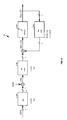
- FIG. 1 is a block diagram illustrating a discrete time symbol-spaced Decision Feedback Equalizer (DFE) based channel equalization model 100.
- the channel equalization model 100 includes a channel 102, a Feed Forward Equalizer (FFE) 104, a Decision block 106, and a Feed Back Equalizer (FBE) 108.
- An input sequence x(n) is complex, independent and identically distributed with unit power.
- Additive noise v ( n ) is white Gaussian with power spectral density ⁇ 2 / ⁇ .
- the decisions (n - ⁇ ) are assumed to be correct, and hence equal to x(n - ⁇ ).
- the FFE 104 function G ( z ) has length L.
- the channel (impulse) response vector of the channel h is given in Equation (1) as:
- the number of coefficients (taps) M of the FBE 108 function B ( z ) is assumed greater or equal to the channel memory, i.e., M ⁇ N -1.
- Equation (2) E
- x n is the 1 ⁇ ( N + L -1) input vector
- y n is the 1 ⁇ L input regression vector to the FFE 104
- n is the 1 ⁇ M input regression vector to the (strictly causal) FBE 108
- v n is the 1 ⁇ L vector noise process.
- the method and system of the present invention computes optimal Decision Feedback Equalizer (DFE) coefficients ⁇ g opt ,b opt ⁇ from a channel estimate h.
- DFE Decision Feedback Equalizer
- a channel impulse response h is first estimated based upon either a known training sequence or an unknown sequence.
- a solution to the DFE coefficient computation problem is then cast as a standard recursive least squares (RLS) problem.
- RLS recursive least squares
- the solution for Feed Forward Equalizer (FFE) coefficients g opt (of the DFE) based upon the channel impulse response h is formulated as the Kalman gain solution to the RLS problem.
- a fast recursive method for computing the Kalman gain is then directly used to compute g opt .
- a fast transversal filter (FTF) technique is employed to compute g opt .
- FTF fast transversal filter
- the complexity of a conventional FTF algorithm is reduced to one third of its original complexity by choosing the length of Feed Back Equalizer (FBE) coefficients b opt (of the DFE) to force the FTF algorithm to use a lower triangular matrix.
- FBE Feed Back Equalizer
- the FBE coefficients b opt are computed by convolving the FFE coefficients g opt with the channel impulse response h.
- a convolution matrix that characterizes the channel impulse response h is extended to a bigger circulant matrix.
- the convolution of the FFE coefficients g opt with the channel impulse response h may be performed the convolution operations in a transformed domain.
- the convolution is performed in the frequency domain, which can be computed efficiently using the Fast Fourier Transform (FFT).
- FFT Fast Fourier Transform
- other transformation domains are employed for the convolution operations, e.g., Discrete Cosine Transformation domain and the Discrete Hadamard Transform domain, among others.
- FFE Feed Forward Equalizer
- determining the delay of the DFE includes determining a delay of the channel based upon the channel response of the channel and adding the delay of the channel to the number of taps of the FFE minus one to produce the delay of the DFE.
- the delay of the channel may be selected as the length of the precursor of the channel response.
- Another technique for determining the delay of the DFE considers the tap energy in the FBE coefficients.
- One embodiment of this technique includes: (1) calculating a plurality of sets of FFE coefficients and FBE coefficients, wherein each of the plurality of sets of FFE coefficients and FBE coefficients corresponds to a respective DFE delay and (2) selecting one of the plurality of sets of FFE coefficients and FBE coefficients based upon the tap energy of the respective FBE coefficients.
- selecting one of the plurality of sets of sets of coefficients includes selecting a set of FFE coefficients and FBE coefficients that meets an FBE coefficient tap energy threshold.
- selecting one of the plurality of sets of sets of coefficients includes selecting a set of FFE coefficients and FBE coefficients that provides a minimum FBE coefficient tap energy.
- the method of the present invention is exact and is much faster than any prior technique that may have been employed to compute DFE coefficients for the same channel and DFE filter lengths. Because the method of the present invention relies upon simple structured recursion, the computation period and/or the hardware required for the DFE coefficient computations is significantly reduced as compared to prior art implementations. The reduction in computation complexity and resultant increase in computation speed enables a DFE that operates according to the present invention to track fast channel variations.
- the method of the preset invention may be efficiently used in many communication systems that require the use of equalizers such as mobile wireless receivers, fixed wireless receivers, cable modem receivers, HDTV receivers, etc. to increase the performance of such communication systems.
- equalizers such as mobile wireless receivers, fixed wireless receivers, cable modem receivers, HDTV receivers, etc.
- FIG. 2 is a logic diagram generally illustrating operation according to the present invention in determining Decision Feedback Equalizer (DFE) coefficients and in applying such coefficients to a DFE.
- DFE Decision Feedback Equalizer
- the operations of the present invention are performed by a processor, such as a Digital Signal Processor (DSP), or other circuitry present within a receiver that determines DFE coefficients to be applied to a DFE, also resident in the receiver.
- DFE operates upon samples of a received signal in an attempt to remove channel effects from the samples so that digital data may be extracted from the samples.
- DFEs one of which was illustrated in FIG. 1, are generally known and will not be further described herein except as they relate to the present invention.
- a processor, tap computer, DSP, or other receiver device, to determine initial DFE coefficients to be used in subsequent operations by the receiver, will first perform the operations of the present invention.
- a channel corresponding to the receiver is estimated (step 202).
- the channel is estimated based upon a known preamble sequence.
- the channel could also be estimated based upon unknown received data. In either case, channel estimation operations are generally well known and are not described further herein except as it relates to the present invention.
- Feed Forward Equalizer (FFE) coefficients are determined based upon the channel estimate (step 206).
- Feed Back Equalizer (FBE) coefficients are determined based upon the FFE coefficients and the channel estimate (step 208).
- the manner in which the FFE and FBE coefficients are generated is step 206 and step 208 will be described in detail herein with reference to FIGs. 3-7.
- the FFE and FBE coefficients determined are applied to the DFE (step 208) and are used in equalizing samples of a received signal to remove channel effects.
- These DFE coefficients are continually updated (step 210) using a known technique.
- the DFE coefficients are again determined (step 212). In this event, another channel estimate may be obtained (step 214). Then, the DFE coefficients are again determined according to the present invention and applied to the DFE. The operations of FIG. 2 continue until the receiver is turned off, placed in a sleep mode, or otherwise inactivated.
- FIG. 3 is a logic diagram illustrating operations according to the present invention employed to determine Feed Forward Equalizer (FFE) coefficients for the DFE.
- FFE Feed Forward Equalizer
- the DFE solution is formulated into a least squares solution (step 304).
- the minimization of the Mean Square Error may be written as:
- H is a submatrix of H as set forth in Equation (5)
- H 1 is defined as the ( ⁇ +1) ⁇ L submatrix of H, consisting of the first ( ⁇ + 1) rows of H .
- the matrix ⁇ 2 / vI should be replaced by the autocorrelation matrix of the noise R v . Extending the derivation to the colored noise case is straightforward.
- Equation (10) becomes: Using the well known inverse formula of block matrices, w opt may be rewritten as: and as: which may be written as:
- each of the two matrices H 1 and H 2 has a shift structure
- the augmented matrix does not have a shift structure
- the expressions for g opt and b opt decouple into a simple form. Therefore, the optimal FFE and FBE coefficients are represented as:
- Equation (2) is equivalent to the solution of Al-Dhahir's equations, due to the uniqueness of w opt when Equation (2) is minimized.
- Equations (26) and (27) provide alternative methods to compute the FFE and FBE coefficients g opt and b op t in a simpler and more efficient way than the prior art techniques.
- the computation of the Kalman gain vector g n+1 in the above solution relies on the propagation of the
- Faster recursions may be obtained by selecting the FBE length. Such selection eliminates certain variables that remain constant and equal to zero during adaptations in the special solution for g opt .
- Fast RLS recursion in its explicit form propagates g n in an efficient manner, see, e.g.: [1] Ljung, M. Morf, and D. Falconer, "Fast calculation of gain matrices for recursive estimation schemes," Int. J. Contr. vol. 27, pp. 1-19, Jan 1978); [2] G. Carayannis, D. Manolakis, and N. Kalouptsidis, "A fast sequential algorithm for least squares filtering and prediction," IEEE Trans. on Acoustic., Speech, Signal Proc., vol.
- Table 1 lists the fast recursions employed in one embodiment for computing the normalized Kalman gain.
- the additional index included in k L, n and ⁇ L (n) stems from the fact that these quantities admit an order-update relation, instead of time-update.
- the purpose of computing k n in the well-known FTF algorithm is to use it in the computation of the corresponding optimal least squared solution for the FFE coefficients. Because we are interested only in k n , the filtering part of the FTF algorithm is not necessary, and does not appear in the algorithm listing.
- Table 2 illustrates a simplified fast recursion for computing the optimal FFE coefficients g opt .
- the FFE coefficients are then determined (step 308).
- the above recursions do not face finite precision difficulties for the following reasons.
- Third, the simplified algorithm deals with a finite set of data ( ⁇ +1 iterations). This algorithm is then reset, which avoids the accumulation of finite precision errors.
- FIG. 4 is a logic diagram illustrating operations according to the present invention employed to determine Feed Back Equalizer (FBE) coefficients for the DFE.
- the FBE coefficients b opt are determined according to the matrix-vector product of Equation (27).
- the computation of the feedback filter coefficients simply amounts to convolution of the channel impulse response with g opt .
- the convolution operation that defines the optimal FBE coefficients in Equation (27) can be computed directly with LM /2 multiplications. Alternatively, the operations may also be efficiently performed using well-known fast FFT convolution techniques.
- Equation (29) is first rewritten in Equation (38) as: The above equality holds true regardless of the values of H 3 , H 4 , or H 5 .
- the matrix C defined by: is a square ( Q ⁇ Q ) circulant matrix, where Q is the smallest power-of-two integer larger than or equal M + L.
- the solution for b opt becomes:
- the complexity of this method is the complexity of obtaining the FFT of two vectors of Q elements of each, the inverse FFT of another Q element vector, and Q complex multiples.
- the overall complexity is Q + 3 Q log 2 ( Q ).
- the complexity is 2 M + 6 M log 2 (2 M ).
- the convolutional matrix H is first determined (step 402). As was previously described, the matrix H may be determined as part of the channel estimation. Then, the convolutional matrix H is extended to form the bigger circulant matrix C (step 404). The bigger circulant matrix C is then converted to the Frequency domain (step 406) as are the FFE coefficients (step 408). With both the bigger circulant matrix C and the FFE coefficients in the frequency domain, they are convolved in the frequency domain by simple matrix multiplication (step 410) to produce the FBE coefficients b opt .
- the resultant FBE coefficients b opt are then converted to the time domain using inverse FFT operations to produce FBE coefficients b opt in the time domain (step 412).
- the FBE coefficients b opt are then applied with the FFE coefficients g opt to the DFE (as previously described with reference to FIG. 2.
- FIG. 5 is a block diagram illustrating a discrete time fractionally-spaced DFE that operates according to the present invention.
- FIG. 6 is a block diagram illustrating a multi-channel equivalent of the discrete time fractionally-spaced DFE of FIG. 5.
- the approach used for the symbol-spaced model can be easily extended to fractionally spaced models.
- the fast solution for the general case of faster over sampling factors, say T / 3, T / 4 , ..., etc. will then follow simply by inspection of the arguments in this section.
- FIGs. 5 and 6 illustrate two equivalent representations for a discrete time model of a T / 2 -spaced equalizer.
- FIG. 5 illustrates a DFE 500 in terms of a down sampler and an up sampler device
- FIG. 6 illustrates a DFE 600 is a corresponding multichannel representation.
- the DFE 500 of FIG. 5 includes a down sampler 502 and an up sampler 504 that alter the sampling frequency.
- the DFE 600 of FIG. 6 includes a first channel function 602 having channel estimate h 0 and corresponding noise function v 0 (n) and FFE 606 coefficients g 0 .
- the DFE 600 of FIG. 6 also includes a second channel function 604 having channel estimate h 1 and corresponding noise function v 1 (n) and FFE 608 coefficients ⁇ g 0 , g 1 ⁇ .
- the quantities ⁇ h 0 , h 1 ⁇ and ⁇ g 0 , g 1 ⁇ are the so-called polyphase components of the channel and FFEs, and are denoted by N and L size vectors ⁇ h 0 , h 1 , ⁇ and ⁇ g 0 , g 1 ⁇ (see FIG. 6).
- the noise sequences ⁇ v 0 ( n ), v 1 ( n ) ⁇ are also the even and odd samples of v(n), with powers 2 ⁇ 2 / v.
- ⁇ H 0 , H 1 ⁇ are the convolution matrices associated with the subchannels ⁇ h 0 , h 1 ⁇ .
- Equation (45) it is more convenient, however, to express the inner product in Equation (45) as a function of the original FFE coefficients vector g , by reordering the entries of g' .
- the procedure to derive a fast recursion in the T/2-spaced case follows the same principle. The only difference here is that the data matrix H ' / ⁇ has now a double shift structure, in the sense that each row is formed by shifting two samples of the channel at a time.
- the fast DFE tap computation is a straightforward extension of the above algorithm, where q is iterated from L to ( L + S -1).
- the RLS problem is formulated as a multi-channel problem.
- a multi-channel Kalman gain is calculated for the multi-channel RLS problem and the FFE taps are determined there from. Note that in the expressions of Table 3, successive order updates are performed.
- F s F ⁇ I s
- C s is a block circulant matrix, which is formed by extending the matrix H in the same manner as in Equation (39).
- the convolution may be performed in a transformed domain, e.g., Frequency Transformation domain, Discrete Cosine Transformation domain and the Discrete Hadamard Transformation domain, among others.
- a Croniker product may be employed in conjunction with such domain transformation in performing multi-channel convolution in the selected transformed domain.
- FIG. 7 is a block diagram illustrating a transceiver constructed according to the present invention.
- the components of the transceiver 700 are resident in a communications device and are illustrated only generally to show how the operations of the present invention would be accomplished in such a transceiver.
- the transceiver 700 includes a receiver section 702 and a transmitter section 704 and further includes either a wireless transceiver 706 or a wired transceiver, depending upon the system in which the transceiver 700 is implemented. In the case of a cellular device, RF device, satellite system device, or another wireless implementation, the transceiver 700 includes a wireless transceiver.
- the transceiver 700 includes a wired transceiver 708.
- the receiver section 702 and transmitter section 704 may couple to a media without a wired transceiver 708.
- SERDES Serializer/Deserializer
- the receiver section 702 receives a baseband signal from the wireless transceiver 706 (or wired transceiver 708) that is baseband modulated and operates upon the baseband signal to extract data.
- These operations include determining DFE coefficients according to the present invention and operating upon the baseband signal using the determined DFE coefficients.
- the transmitter section 704 receives digital data to be transmitted from a host, codes the digital data into a baseband signal, and passes the baseband signal to the RF transceiver 706.
- the RF transceiver 706 couples the baseband signal to an RF carrier to create an RF signal and transmits the RF signal to a receiving device across a wireless link.
- the receiver section 702 receives a baseband signal that carries coded data from the RF transceiver 706.
- a Programmable Gain Amplifier (PGA) 712 adjusts the gain of the baseband signal and then provides the gain-adjusted baseband signal to an Analog-to-Digital Converter (ADC) 714 for sampling.
- the ADC 208 samples the gain adjusted baseband signal at a particular sampling frequency, f s (that is the symbol clock frequency), to produce samples thereof.
- a processor 710 couples to the output of the ADC 714 and analyzes a preamble sequence contained in each received physical layer frame. Based upon the preamble sequence, the processor 710 determines a gain to be applied to portions of the baseband signal corresponding to the data carrying portions of the frame and provides this gain to the PGA 712. Further, the processor 710 may also interact with the optional timing compensation section 716 to compensate for symbol timing and RF carrier mismatches.
- the processor 710 based upon the preamble sequence (and based upon actual extracted data in some operations), also determines FFE 104 and FBE 108 coefficients. The manner in which these coefficients are determined was previously described in detail herein. Further, and as was also previously described, the processor 710 may estimate a channel and calculate DFE coefficients based upon unknown but assumed data content. After the processor 710 determines these coefficients, they are applied to the FFE 104 and FBE 108 for subsequent use in extracting data from the baseband signal.
- the structure described in FIG. 7 may be embodied using various types of circuits formed using various manufacturing processes.
- the RF transceiver 706 (or wired transceiver 708) is embodied in a first integrated circuit that is coupled to a second integrated circuit that includes the transmitter section 704 and the receiver section 702, among other circuits.
- the RF transceiver 706, the transmitter section 704 and the receiver section 702 are all formed on a single monolithic integrated circuit.
- These integrated circuits may be constructed in CMOS or another semiconductor technology, e.g., PMOS, NMOS, Bipolar, etc.
- the receiver section 702 of FIG. 7 may be constructed using various circuit elements/combinations.
- all structures past the ADC 714 in the receiver section 702 are embodied using a Digital Signal Processor (DSP) or similar processing device.
- DSP Digital Signal Processor
- dedicated signal path circuitry embodies each of the structural components of the receiver section 702, including the processor 710. While a DSP implementation would provide more flexibility, dedicated signal path circuitry would typically provide higher performance at a lower cost and with lower power consumption.
- the structure and operation of the present invention may be employed in satellite communication systems, satellite television systems, HDTV systems, fixed wireless communication systems, mobile wireless communication systems, cable modem/television communication systems, home networking systems, wireless local area networking systems, wired local area networking systems, and many other types of communication systems.
- the present invention applies to all types of communication devices in which equalizers are employed to operate upon received signals.
- FIG. 8 is a block diagram illustrating a Multi-Input-Multi-Output (MIMO) digital communication system that operates according to the present invention to equalize a channel.
- MIMO digital communication systems are communication systems that include multiple inputs on a transmitting side and multiple outputs on a receiving side. In such systems, MIMO decision feedback equalization is used to mitigate inter-symbol interference (ISI) that results from channel multi path propagation.
- ISI inter-symbol interference
- an input symbol stream includes P unique transmitted signals, represented by x 0 ( n ), x 1 ( n ), ..., x p -1 ( n ) (as are further shown with reference to FIGS. 8, 9, and 10).
- the nomenclature of FIG. 8 is used herein to describe the method of the present invention.
- the P transmitted signals are referred to in combination as transmitted signal vector x ( n ).
- the transmitted signal vector x ( n ) consists of a known training sequence followed by unknown data.
- the transmitted signal vector x(n) passes through a channel 802 represented by H ( z ) that is represented to have N taps.
- the channel 802 includes additive noise v ( n ), which is white and Gaussian and has power spectral density ⁇ 2 / v .
- the output of the channel 804 is referred to as y(n) and has a length Q (the value Q is a function of P and N).
- a MIMO DFE that equalizes the channel includes a MIMO FFE 804 having function G(z) and length L and a MIMO FBE 808 having function B(z) and length M (that is assumed to be greater or equal to the channel memory, i.e., M ⁇ N -1).
- the outputs of both the MIMO FFE 804 and the MIMO FBE 808 have a width P that corresponds to the multiple numbers of signals.
- MIMO decision block 806 makes soft decisions for the MIMO symbol stream and produces as P output symbol streams o ( n - ⁇ ), 1 ( n - ⁇ ), ..., p -1 ( n - ⁇ ). These soft decisions are provided to further receiver components, e.g., a Viterbi decoder to produce hard decisions based upon the soft decisions.
- Examples of systems in which the MIMO DFE of the present invention may be implemented include wireless systems, e.g., cellular wireless systems, fixed local loop wireless systems, wireless local area networks, high definition television systems, etc., and wired systems in which multiple transmitters and receives share a common media, e.g., cable modem systems, etc. Diagrams representing such systems are illustrated in FIGs. 9, 10, and 11. The structure of FIG. 7 may be employed to implement the structure and operations described with reference to FIGs. 8-11.
- FIG. 9 is a system diagram illustrating a wireless digital communication system 900 in which a MIMO receiver 904 operates according to the present invention.
- the wireless system 900 includes a MIMO transmitter 902 that operates to receive a plurality of signal streams and to form a wireless signal and that transmits the wireless signal.
- the MIMO receiver 904 receives the wireless signal after a corresponding channel has operated upon it.
- the MIMO receiver 904 includes a MIMO DFE that operates according to the present invention to equalize the received signal and to produce output based thereupon. As is illustrated, the MIMO receiver 904 may include antenna diversity structure.
- FIG. 10 is a system diagram illustrating a wireless digital communication system 1000 that includes a plurality of transmitters 1002A-1002G and a MIMO receiver 1004 that operates according to the present invention.
- Each of the plurality of transmitters 1002A-1002G produces a respective transmitted signal that carries a respective input symbol stream, x 1 (n), x 2 (n), ..., x p (n).
- the MIMO receiver 1004 receives the plurality of transmitted signals as a composite signal after they have been operated upon the channel, equalizes the plurality of received signals, and produces soft decisions for the equalized symbols.
- the MIMO receiver 904 may include antenna diversity structure.
- FIG. 11 is a system diagram illustrating a wired digital communication system 1100 that includes a plurality of transmitters 1102A-1102G and a MIMO receiver 1104 that operates according to the present invention.
- Each of the plurality of transmitters 1102A-1102G produces a respective transmitted signal that carries a respective input symbol stream, x 0 (n), x 1 (n), ..., x p-1 (n) and couples its respective signal to a network infrastructure 1106.
- the MIMO receiver 1104 couples to the network infrastructure 1106 and receives the plurality of transmitted signals as a composite signal after they have been operated upon the channel, equalizes the plurality of received signals, and produces soft decisions for the equalized symbols.
- the wired digital communication system 1000 of FIG. 11 may be embodied in a cable modem system, or in another type of system in which the MIMO receiver 1004 receives wired transmissions from a plurality of transmitters 1002A-1002G
- an efficient equalization technique for equalizing a channel in a MIMO system includes first estimating the channel impulse responses between each transmitter and each receiver using the training sequence, and then using this estimate to compute the optimal DFE tap coefficients corresponding to the estimated channel.
- the computed tap coefficients are then uploaded to the equalizer taps of the MIMO FFE (including MIMO FFE 804 and MIMO FBE 808) of FIG. 8. This procedure should be repeated as often as possible, especially in cases of fast varying channels.
- the received data stream is usually buffered during the period assigned for the channel estimation and the equalizer tap computation.
- an efficient method for computing the optimal MIMO MMSE-DFE coefficients includes characterizing a solution to the problem of solving for MIMO FBE and FFE coefficients as a fast recursive-least-squares (RLS) adaptive algorithm.
- This fast algorithm has the following advantages over the current most efficient algorithm: (1) the proposed algorithm has less overall computational complexity than prior techniques in solving for DFEs having the same channel and DFE filters length; and (2) the technique relies on the use of a set of structured recursions, which makes it attractive in data-path implementations which do not rely on the use of a DSP core.
- the noise sequences ⁇ v q ( n ) ⁇ are assumed to be white Gaussian with power ⁇ 2 / v,i .
- the autocorrelation matrix of size LQ of the corresponding vector noise process v ( n ) is given by:
- the MIMO FFE 804 has a matrix filter G ( z ) with length L.
- the number of matrix taps M of the MIMO FBE 808 having matrix filter B (z) is such that M ⁇ N -1.
- H is the ( N + L - 1) P ⁇ LQ convolution matrix associated with the channel matrix coefficients h (0), h (1),..., h ( N - 1), and is given by:
- the row vector x n is the 1 ⁇ ( N + L -1) P input regressor: With x ( n ) [ x 0 ( n ) ⁇ 1 (n) ... x P- 1 ( n )].
- the row vector y n is the 1 ⁇ LQ input regressor to the feed forward filter g , i.e., Where y ( n ) ⁇ y 0 ( n ) y 1 ( n ) ...
- n is the 1 ⁇ MP input regressor to the (strictly causal) feedback filter b, i.e., Where ⁇ b i ⁇ are P ⁇ P .
- v n is the 1 ⁇ LQ noise vector process.
- Equation (55) By collecting g and b into a single matrix w , the minimization of Equation (55) can be written as:
- Equation (65) becomes:
- Equation (74) may be rewritten as:
- the key to achieving fast recursions is to propagate k n efficiently, by successive order updates and order down dates of k n , using forward and backward LS prediction problems.
- the well-known fast transversal filter (FTF) is an example where such fast technique is encountered, see e.g., J. Cioffi and T. Kailath, "Fast recursive-least-squares transversal filters for adaptive filtering," IEEE Trans. on Acoust., Speech Signal Processing, vol. ASSP-32, pp. 304-337
- the entries of the regressor h n are the channel matrix coefficients h (0),..., h ( N - 1), each of size P ⁇ Q (In the multi channel RLS equations, the entries of the regressor are usually given by a row or a column vector, and the recursions have no matrix inversions).
- the resulting algorithm is then given by consecutive updates of Q forward prediction problems where we estimate the columns of h ( n ) from h n -1 and compute the corresponding forward prediction matrix-valued quantities.
- Table 4 lists the resulting multi channel algorithm.
- b opt in equation (36) can be performed efficiently via using fast Fourier transform techniques. This can be done by extending the block Toeplitz structure of H to form a KP ⁇ KQ block-circulant matrix C P,Q , where each block entry has size P ⁇ Q (see, e.g., M. Vollmer, J. Gotze, M Haardt, "Efficient Joint Detection Techniques for TD-CDMA in the Frequency Domain," COST 262 Workshop “Multiuser Detection in Spread Spectrum Communications", Ulm, Germany, 2001).
- the diagonal elements of ⁇ P,Q can thus be computed from the block-DFT of the first block-column of C P,Q .
- the b opt then becomes Hence, the complexity is given b P inverse FFTs, Q FFTs, and P FFTs of size K, and KPQ complex multiplies.
- the overall complexity for computing the feedback filter is KPQ + (2 P + Q ) K log 2 K ).
- FIG. 12 is logic diagram illustrating operation according to another embodiment of the present invention for determining FFE coefficients.
- the operations of FIG. 12 differ from the operations of FIG. 3 in that the delay of FBE is not limited to being less than or equal to the length of the FFE but is chosen to correspond to the channel being equalized (step 1202).
- FIGs. 14 and 15 describe differing techniques for selecting the DFE delay. Referring still to FIG. 12, operation continues by formulating a solution that, when solved, will yield the DFE coefficients, wherein the solution is formulated as a least squares problem that is based upon the channel response (step 1204).
- the operation considers whether the DFE delay is greater than the length of the FFE minus one, i.e., is the DFE delay greater than the FFE delay (step 1206).
- the method includes solving the least squares problem to yield FFE coefficients of the DFE coefficients by performing a first set of operations (step 1208).
- operation includes solving the least squares problem to yield FFE coefficients of the DFE coefficients by performing a first set of operations (step 1210) and by performing a second set of operations (step 1212).
- the method includes (from step 1208 and from step 1212) convolving the FFE coefficients with a convolution matrix that is based upon the channel response to yield FBE coefficients of the DFE coefficients (step 1214).
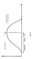
- FIG. 13 is a graph illustrating a hypothetical channel impulse response indicating how channel delay may be determined according to the present invention.
- the channel delay ⁇ c could be computed as the index of the strongest channel tap.
- FIG. 14 is a logic diagram illustrating operation according to a first embodiment of the present invention in selecting FBE coefficients.
- This operation includes first selecting an initial equalizer delay value (step 1402). Then, for the particular equalizer delay value (FBE delay), the operation includes calculating a set of FFE coefficients and FBE coefficients (step 1404). Then operation then includes determining the FBE tap energy for the particular FBE delay (step 1406). If this FBE tap energy is less than a FBE tap energy threshold (as determined at step 1408) the FFE and FBE coefficients determined for the particular FBE are employed (step 1414).
- step 1410 If the FBE tap energy is not less than the FBE tap energy threshold (as determined at step 1408), it is next determined whether the FBE delay is at a maximum (step 1410). If so, no acceptable FBE coefficients have been determined for the particular channel response and FBE configuration, the operation has failed (step 1416). However, if the FBE delay is not at a maximum (as determined at step 1410), the equalizer delay is increased by a step size (or otherwise altered as may be appropriate for the given operations) at step 1412 and operation returns to step 1404.
- FIG. 15 is a logic diagram illustrating operation according to a second embodiment of the present invention in selecting FBE coefficients.
- This operation includes first selecting an initial equalizer delay value (step 1502). Then, for the particular equalizer delay value (FBE delay), the operation includes calculating a set of FFE coefficients and FBE coefficients (step 1504). Then operation then includes determining the FBE tap energy for the particular FBE delay (step 1506). The operation then includes storing the FFE coefficients, the FBE coefficients, and the FBE tap energy along with the particular FBE delay (step 1508). It is next determined whether the FBE delay is at a maximum (step 1510).
- the FFE coefficients, FBE coefficients, and FBE delay is selected that corresponds to a minimum FBE tap energy (step 1516) of all solutions that have been stored. If the FBE delay is not at the maximum FBE delay (as determined at step 1510), the equalizer delay is increased by a step size (or otherwise altered as may be appropriate for the given operations) at step 1512 and operation returns to step 1504.
Landscapes
- Engineering & Computer Science (AREA)
- Computer Networks & Wireless Communication (AREA)
- Signal Processing (AREA)
- Power Engineering (AREA)
- Cable Transmission Systems, Equalization Of Radio And Reduction Of Echo (AREA)
Applications Claiming Priority (4)
| Application Number | Priority Date | Filing Date | Title |
|---|---|---|---|
| US154947 | 1980-05-30 | ||
| US10/154,947 US7113540B2 (en) | 2001-09-18 | 2002-05-24 | Fast computation of multi-input-multi-output decision feedback equalizer coefficients |
| US10/390,366 US7263123B2 (en) | 2001-09-18 | 2003-03-17 | Fast computation of coefficients for a variable delay decision feedback equalizer |
| US390366 | 2003-03-17 |
Publications (2)
| Publication Number | Publication Date |
|---|---|
| EP1365554A1 true EP1365554A1 (de) | 2003-11-26 |
| EP1365554B1 EP1365554B1 (de) | 2007-01-24 |
Family
ID=29406300
Family Applications (1)
| Application Number | Title | Priority Date | Filing Date |
|---|---|---|---|
| EP03011533A Expired - Lifetime EP1365554B1 (de) | 2002-05-24 | 2003-05-21 | Errechnung der Koeffizienten für einen entscheidungsrückgekoppelten Entzerrer änderbarer Verzögerung |
Country Status (3)
| Country | Link |
|---|---|
| US (1) | US7263123B2 (de) |
| EP (1) | EP1365554B1 (de) |
| DE (1) | DE60311348T2 (de) |
Cited By (6)
| Publication number | Priority date | Publication date | Assignee | Title |
|---|---|---|---|---|
| US7042967B2 (en) | 2003-03-03 | 2006-05-09 | Interdigital Technology Corporation | Reduced complexity sliding window based equalizer |
| US7428279B2 (en) | 2003-03-03 | 2008-09-23 | Interdigital Technology Corporation | Reduced complexity sliding window based equalizer |
| EP1776818A4 (de) * | 2004-08-13 | 2009-06-17 | Agency Science Tech & Res | Verfahren zum entzerren eines digitalsignals und entzerrer |
| CN1845539B (zh) * | 2005-04-08 | 2010-12-29 | 上海奇普科技有限公司 | 一种具有重叠结构的时域自适应均衡器 |
| CN104079513A (zh) * | 2013-03-27 | 2014-10-01 | 想象力科技有限公司 | 初始均衡器系数的高效计算 |
| CN111884706A (zh) * | 2020-07-17 | 2020-11-03 | 北京和德宇航技术有限公司 | 一种卫星频谱检测方法、装置、设备和存储介质 |
Families Citing this family (117)
| Publication number | Priority date | Publication date | Assignee | Title |
|---|---|---|---|---|
| US7027504B2 (en) * | 2001-09-18 | 2006-04-11 | Broadcom Corporation | Fast computation of decision feedback equalizer coefficients |
| US7382827B2 (en) * | 2001-09-18 | 2008-06-03 | Broadcom Corporation | Computation of decision feedback equalizer coefficients with constrained feedback tap energy |
| GB2392067B (en) * | 2002-08-16 | 2005-04-06 | Toshiba Res Europ Ltd | Channel estimation apparatus and methods |
| US6873596B2 (en) * | 2003-05-13 | 2005-03-29 | Nokia Corporation | Fourier-transform based linear equalization for CDMA downlink |
| JP3970807B2 (ja) * | 2003-06-18 | 2007-09-05 | 三菱電機株式会社 | 無線通信装置 |
| US7616698B2 (en) | 2003-11-04 | 2009-11-10 | Atheros Communications, Inc. | Multiple-input multiple output system and method |
| EP1531590A1 (de) * | 2003-11-11 | 2005-05-18 | STMicroelectronics Belgium N.V. | Verfahren und Vorrichtung zur Kanalentzerrung unter Verwendung einer Schätzung der Länge der Kanalimpulsantwort |
| US7492749B2 (en) * | 2004-05-19 | 2009-02-17 | The Directv Group, Inc. | Method and system for providing multi-input-multi-output (MIMO) downlink transmission |
| US7545875B2 (en) | 2004-11-03 | 2009-06-09 | Nokia Corporation | System and method for space-time-frequency coding in a multi-antenna transmission system |
| US8218615B2 (en) * | 2005-03-29 | 2012-07-10 | Qualcomm Incorporated | Method and apparatus for block-wise decision-feedback equalization for wireless communication |
| US8615035B2 (en) | 2005-03-29 | 2013-12-24 | Qualcomm Incorporated | Method and apparatus for block-wise decision-feedback equalization for wireless communication |
| US8743943B2 (en) * | 2005-07-28 | 2014-06-03 | Altera Corporation | High-speed data reception circuitry and methods |
| CN100340077C (zh) * | 2005-11-29 | 2007-09-26 | 东南大学 | 多天线无线传输系统中信道环境自适应传输方法 |
| JP5202340B2 (ja) | 2006-03-24 | 2013-06-05 | ジェネラル・インスツルメント・コーポレーション | ネットワークにおける論理チャネルを構成するための装置、方法、およびコンピュータ読取可能な記録媒体 |
| US9088355B2 (en) | 2006-03-24 | 2015-07-21 | Arris Technology, Inc. | Method and apparatus for determining the dynamic range of an optical link in an HFC network |
| FI20065276A0 (fi) * | 2006-04-28 | 2006-04-28 | Nokia Corp | Signaalin käsittelymenetelmä, vastaanotin ja tasoitusmenetelmä vastaanottimessa |
| US8121209B2 (en) | 2006-07-25 | 2012-02-21 | Marvell World Trade Ltd. | Concatenation-assisted symbol-level combining for MIMO systems with HARQ and/or repetition coding |
| US8929472B1 (en) | 2006-07-26 | 2015-01-06 | Marvell International Ltd. | Bit-level combining for MIMO systems with HARQ and/or repetition coding |
| US8718166B2 (en) | 2006-08-08 | 2014-05-06 | Marvell World Trade Ltd. | Maximal ratio combining of equalized symbols for MIMO systems with HARQ and/or repetition coding |
| US8699601B1 (en) | 2006-08-08 | 2014-04-15 | Marvell World Trade Ltd. | Distance-level combining for MIMO systems with HARQ and/or repetition coding |
| US8411778B1 (en) | 2006-08-08 | 2013-04-02 | Marvell World Trade Ltd. | Optimal linear equalizer for MIMO systems with HARQ and/or repetition coding |
| US8537972B2 (en) | 2006-12-07 | 2013-09-17 | General Instrument Corporation | Method and apparatus for determining micro-reflections in a network |
| US8619910B1 (en) * | 2007-04-11 | 2013-12-31 | Marvell International Ltd. | Decision feedback equalization for MIMO systems with hybrid ARQ |
| US8711916B2 (en) | 2007-07-27 | 2014-04-29 | Intel Corporation | Tap initialization of equalizer based on estimated channel impulse response |
| US7978757B1 (en) | 2008-02-08 | 2011-07-12 | Freescale Semiconductor, Inc. | Configurable receiver and a method for configuring a receiver |
| US8130021B2 (en) * | 2009-01-09 | 2012-03-06 | International Business Machines Corporation | Gain control with multiple integrators |
| US7982992B2 (en) | 2009-01-09 | 2011-07-19 | International Business Machines Corporation | Dual gain control for magnetic data storage system |
| US7924524B2 (en) * | 2009-01-09 | 2011-04-12 | International Business Machines Corporation | System and method for generating an amplitude error signal in a magnetic tape recording channel |
| US8229020B2 (en) * | 2009-03-23 | 2012-07-24 | Oracle America, Inc. | Integrated equalization and CDR adaptation engine with single error monitor circuit |
| GB2471694A (en) * | 2009-07-08 | 2011-01-12 | Toshiba Res Europ Ltd | Determining receiver beam forming vectors in multi-user multiple-input multiple-output (MIMO) systems |
| US8516532B2 (en) | 2009-07-28 | 2013-08-20 | Motorola Mobility Llc | IP video delivery using flexible channel bonding |
| US8526485B2 (en) | 2009-09-23 | 2013-09-03 | General Instrument Corporation | Using equalization coefficients of end devices in a cable television network to determine and diagnose impairments in upstream channels |
| US8284828B2 (en) * | 2009-11-11 | 2012-10-09 | General Instrument Corporation | Monitoring instability and resetting an equalizer |
| US9071285B2 (en) | 2011-05-26 | 2015-06-30 | Cohere Technologies, Inc. | Modulation and equalization in an orthonormal time-frequency shifting communications system |
| US9130638B2 (en) * | 2011-05-26 | 2015-09-08 | Cohere Technologies, Inc. | Modulation and equalization in an orthonormal time-frequency shifting communications system |
| US10667148B1 (en) | 2010-05-28 | 2020-05-26 | Cohere Technologies, Inc. | Methods of operating and implementing wireless communications systems |
| US11943089B2 (en) | 2010-05-28 | 2024-03-26 | Cohere Technologies, Inc. | Modulation and equalization in an orthonormal time-shifting communications system |
| US9444514B2 (en) | 2010-05-28 | 2016-09-13 | Cohere Technologies, Inc. | OTFS methods of data channel characterization and uses thereof |
| US8976851B2 (en) | 2011-05-26 | 2015-03-10 | Cohere Technologies, Inc. | Modulation and equalization in an orthonormal time-frequency shifting communications system |
| US10681568B1 (en) | 2010-05-28 | 2020-06-09 | Cohere Technologies, Inc. | Methods of data channel characterization and uses thereof |
| US9071286B2 (en) | 2011-05-26 | 2015-06-30 | Cohere Technologies, Inc. | Modulation and equalization in an orthonormal time-frequency shifting communications system |
| US8654640B2 (en) | 2010-12-08 | 2014-02-18 | General Instrument Corporation | System and method for IP video delivery using distributed flexible channel bonding |
| US8937992B2 (en) | 2011-08-30 | 2015-01-20 | General Instrument Corporation | Method and apparatus for updating equalization coefficients of adaptive pre-equalizers |
| US8576705B2 (en) | 2011-11-18 | 2013-11-05 | General Instrument Corporation | Upstream channel bonding partial service using spectrum management |
| US9113181B2 (en) | 2011-12-13 | 2015-08-18 | Arris Technology, Inc. | Dynamic channel bonding partial service triggering |
| US8867371B2 (en) | 2012-04-27 | 2014-10-21 | Motorola Mobility Llc | Estimating physical locations of network faults |
| US8837302B2 (en) | 2012-04-27 | 2014-09-16 | Motorola Mobility Llc | Mapping a network fault |
| US8868736B2 (en) | 2012-04-27 | 2014-10-21 | Motorola Mobility Llc | Estimating a severity level of a network fault |
| US9003460B2 (en) | 2012-04-27 | 2015-04-07 | Google Technology Holdings LLC | Network monitoring with estimation of network path to network element location |
| US9065731B2 (en) | 2012-05-01 | 2015-06-23 | Arris Technology, Inc. | Ensure upstream channel quality measurement stability in an upstream channel bonding system using T4 timeout multiplier |
| US8559496B1 (en) * | 2012-06-20 | 2013-10-15 | MagnaCom Ltd. | Signal reception using non-linearity-compensated, partial response feedback |
| US10411843B2 (en) | 2012-06-25 | 2019-09-10 | Cohere Technologies, Inc. | Orthogonal time frequency space communication system compatible with OFDM |
| US10469215B2 (en) | 2012-06-25 | 2019-11-05 | Cohere Technologies, Inc. | Orthogonal time frequency space modulation system for the Internet of Things |
| US10090972B2 (en) | 2012-06-25 | 2018-10-02 | Cohere Technologies, Inc. | System and method for two-dimensional equalization in an orthogonal time frequency space communication system |
| US9912507B2 (en) | 2012-06-25 | 2018-03-06 | Cohere Technologies, Inc. | Orthogonal time frequency space communication system compatible with OFDM |
| US9929783B2 (en) | 2012-06-25 | 2018-03-27 | Cohere Technologies, Inc. | Orthogonal time frequency space modulation system |
| US10003487B2 (en) | 2013-03-15 | 2018-06-19 | Cohere Technologies, Inc. | Symplectic orthogonal time frequency space modulation system |
| US9136943B2 (en) | 2012-07-30 | 2015-09-15 | Arris Technology, Inc. | Method of characterizing impairments detected by equalization on a channel of a network |
| US9137164B2 (en) | 2012-11-15 | 2015-09-15 | Arris Technology, Inc. | Upstream receiver integrity assessment for modem registration |
| US9203639B2 (en) | 2012-12-27 | 2015-12-01 | Arris Technology, Inc. | Dynamic load balancing under partial service conditions |
| US9197886B2 (en) | 2013-03-13 | 2015-11-24 | Arris Enterprises, Inc. | Detecting plant degradation using peer-comparison |
| US10477199B2 (en) | 2013-03-15 | 2019-11-12 | Arris Enterprises Llc | Method for identifying and prioritizing fault location in a cable plant |
| US9025469B2 (en) | 2013-03-15 | 2015-05-05 | Arris Technology, Inc. | Method for estimating cable plant topology |
| US9042236B2 (en) | 2013-03-15 | 2015-05-26 | Arris Technology, Inc. | Method using equalization data to determine defects in a cable plant |
| GB2503073B (en) * | 2013-03-27 | 2014-04-23 | Imagination Tech Ltd | Efficient tracking of decision-feedback equaliser coefficients |
| WO2016030758A2 (en) * | 2014-08-27 | 2016-03-03 | MagnaCom Ltd. | Multiple input multiple output communications over nonlinear channels using orthogonal frequency division multiplexing |
| CN107925434B (zh) | 2015-05-11 | 2021-02-05 | 凝聚技术公司 | 用于数据的辛正交时频移位调制和传输的系统和方法 |
| US10090973B2 (en) | 2015-05-11 | 2018-10-02 | Cohere Technologies, Inc. | Multiple access in an orthogonal time frequency space communication system |
| US9866363B2 (en) | 2015-06-18 | 2018-01-09 | Cohere Technologies, Inc. | System and method for coordinated management of network access points |
| US10574317B2 (en) | 2015-06-18 | 2020-02-25 | Cohere Technologies, Inc. | System and method for providing wireless communication services using configurable broadband infrastructure shared among multiple network operators |
| US10404514B2 (en) | 2015-06-27 | 2019-09-03 | Cohere Technologies, Inc. | Orthogonal time frequency space communication system compatible with OFDM |
| US10693581B2 (en) | 2015-07-12 | 2020-06-23 | Cohere Technologies, Inc. | Orthogonal time frequency space modulation over a plurality of narrow band subcarriers |
| CN108770382B (zh) | 2015-09-07 | 2022-01-14 | 凝聚技术公司 | 使用正交时间频率空间调制的多路存取的方法 |
| US11038733B2 (en) | 2015-11-18 | 2021-06-15 | Cohere Technologies, Inc. | Orthogonal time frequency space modulation techniques |
| WO2017100666A1 (en) | 2015-12-09 | 2017-06-15 | Cohere Technologies | Pilot packing using complex orthogonal functions |
| US10666314B2 (en) | 2016-02-25 | 2020-05-26 | Cohere Technologies, Inc. | Reference signal packing for wireless communications |
| WO2017165697A1 (en) | 2016-03-23 | 2017-09-28 | Cohere Technologies | Receiver-side processing of orthogonal time frequency space modulated signals |
| WO2017173160A1 (en) | 2016-03-31 | 2017-10-05 | Cohere Technologies | Channel acquisition using orthogonal time frequency space modulated pilot signal |
| US9667307B1 (en) | 2016-03-31 | 2017-05-30 | Cohere Technologies | Wireless telecommunications system for high-mobility applications |
| US10063295B2 (en) | 2016-04-01 | 2018-08-28 | Cohere Technologies, Inc. | Tomlinson-Harashima precoding in an OTFS communication system |
| CN113726700B (zh) | 2016-04-01 | 2024-09-24 | 凝聚技术公司 | 通过执行迭代均衡来从接收信号中恢复信息位的无线通信方法和设备 |
| US10938602B2 (en) | 2016-05-20 | 2021-03-02 | Cohere Technologies, Inc. | Iterative channel estimation and equalization with superimposed reference signals |
| EP3497785B1 (de) | 2016-08-12 | 2024-03-13 | Cohere Technologies, Inc. | Verfahren zur mehrbenutzer-multiplexen von orthogonalen zeitfrequenzraumsignalen |
| WO2018031952A1 (en) | 2016-08-12 | 2018-02-15 | Cohere Technologies | Iterative multi-level equalization and decoding |
| EP3497907A4 (de) | 2016-08-12 | 2020-03-04 | Cohere Technologies, Inc. | Lokalisierte entzerrung für kanäle mit zwischenträgerinterferenzen |
| WO2018064587A1 (en) | 2016-09-29 | 2018-04-05 | Cohere Technologies | Transport block segmentation for multi-level codes |
| US10965348B2 (en) | 2016-09-30 | 2021-03-30 | Cohere Technologies, Inc. | Uplink user resource allocation for orthogonal time frequency space modulation |
| WO2018106731A1 (en) | 2016-12-05 | 2018-06-14 | Cohere Technologies | Fixed wireless access using orthogonal time frequency space modulation |
| EP3566379B1 (de) | 2017-01-09 | 2024-12-11 | Cohere Technologies, Inc. | Pilotverschlüsselung zur kanalschätzung |
| US10356632B2 (en) | 2017-01-27 | 2019-07-16 | Cohere Technologies, Inc. | Variable beamwidth multiband antenna |
| US10568143B2 (en) | 2017-03-28 | 2020-02-18 | Cohere Technologies, Inc. | Windowed sequence for random access method and apparatus |
| WO2018191309A1 (en) | 2017-04-11 | 2018-10-18 | Cohere Technologies | Digital communication using dispersed orthogonal time frequency space modulated signals |
| WO2018195548A1 (en) | 2017-04-21 | 2018-10-25 | Cohere Technologies | Communication techniques using quasi-static properties of wireless channels |
| WO2018200577A1 (en) | 2017-04-24 | 2018-11-01 | Cohere Technologies | Digital communication using lattice division multiplexing |
| WO2018200567A1 (en) | 2017-04-24 | 2018-11-01 | Cohere Technologies | Multibeam antenna designs and operation |
| CN111052692B (zh) | 2017-07-12 | 2022-10-11 | 凝聚技术公司 | 基于zak变换的数据调制方法 |
| WO2019032605A1 (en) | 2017-08-11 | 2019-02-14 | Cohere Technologies | RADIATION TRACING TECHNIQUE FOR WIRELESS CHANNEL MEASUREMENTS |
| WO2019036492A1 (en) | 2017-08-14 | 2019-02-21 | Cohere Technologies | ASSIGNMENT OF TRANSMISSION RESOURCES BY DIVISION OF BLOCKS OF PHYSICAL RESOURCES |
| WO2019051093A1 (en) | 2017-09-06 | 2019-03-14 | Cohere Technologies | REDUCTION OF TRELLIS IN TIME, FREQUENCY AND ORTHOGONAL SPATIAL MODULATION |
| US11283561B2 (en) | 2017-09-11 | 2022-03-22 | Cohere Technologies, Inc. | Wireless local area networks using orthogonal time frequency space modulation |
| US11190308B2 (en) | 2017-09-15 | 2021-11-30 | Cohere Technologies, Inc. | Achieving synchronization in an orthogonal time frequency space signal receiver |
| WO2019060596A2 (en) | 2017-09-20 | 2019-03-28 | Cohere Technologies, Inc. | LOW COST ELECTROMAGNETIC POWER SUPPLY NETWORK |
| TWI672007B (zh) * | 2017-09-26 | 2019-09-11 | 北京集創北方科技股份有限公司 | 快速通道檢測和補償電路及利用其之通信裝置 |
| US11152957B2 (en) | 2017-09-29 | 2021-10-19 | Cohere Technologies, Inc. | Forward error correction using non-binary low density parity check codes |
| WO2019089986A1 (en) | 2017-11-01 | 2019-05-09 | Cohere Technologies, Inc. | Precoding in wireless systems using orthogonal time frequency space multiplexing |
| US11184122B2 (en) | 2017-12-04 | 2021-11-23 | Cohere Technologies, Inc. | Implementation of orthogonal time frequency space modulation for wireless communications |
| WO2019157230A1 (en) | 2018-02-08 | 2019-08-15 | Cohere Technologies, Inc. | Aspects of channel estimation for orthogonal time frequency space modulation for wireless communications |
| US11489559B2 (en) | 2018-03-08 | 2022-11-01 | Cohere Technologies, Inc. | Scheduling multi-user MIMO transmissions in fixed wireless access systems |
| US11178751B2 (en) | 2018-03-16 | 2021-11-16 | Dell Products L.P. | Printed circuit board having vias arranged for high speed serial differential pair data links |
| US10298420B1 (en) | 2018-03-20 | 2019-05-21 | Dell Products, Lp | System and method to enhance feed-forward equalization in a high-speed serial interface |
| US11329848B2 (en) | 2018-06-13 | 2022-05-10 | Cohere Technologies, Inc. | Reciprocal calibration for channel estimation based on second-order statistics |
| US11522600B1 (en) | 2018-08-01 | 2022-12-06 | Cohere Technologies, Inc. | Airborne RF-head system |
| US11336490B2 (en) | 2020-03-13 | 2022-05-17 | Texas Instruments Incorporated | DFE implementation for wireline applications |
| US11502715B2 (en) * | 2020-04-29 | 2022-11-15 | Eagle Technology, Llc | Radio frequency (RF) system including programmable processing circuit performing block coding computations and related methods |
| US11411593B2 (en) * | 2020-04-29 | 2022-08-09 | Eagle Technology, Llc | Radio frequency (RF) system including programmable processing circuit performing butterfly computations and related methods |
| US12335081B2 (en) | 2021-04-29 | 2025-06-17 | Cohere Technologies, Inc. | Ultra wide band signals using orthogonal time frequency space modulation |
| US11581951B1 (en) * | 2022-01-31 | 2023-02-14 | Huawei Technologies Co., Ltd. | Apparatuses and methods of far-end transmitter skew monitoring in digital subcarrier multiplexing systems |
Citations (1)
| Publication number | Priority date | Publication date | Assignee | Title |
|---|---|---|---|---|
| EP1248425A1 (de) * | 2001-04-06 | 2002-10-09 | Ascom Systec AG | Ausrechnung von DFE-Koeffizienten aus der Kanalimpulsantwort |
Family Cites Families (4)
| Publication number | Priority date | Publication date | Assignee | Title |
|---|---|---|---|---|
| US5946351A (en) * | 1996-12-27 | 1999-08-31 | At&T Corporation | Tap selectable decision feedback equalizer |
| US6445734B1 (en) * | 1999-06-30 | 2002-09-03 | Conexant Systems, Inc. | System and method of validating equalizer training |
| KR100617778B1 (ko) * | 1999-07-07 | 2006-08-28 | 삼성전자주식회사 | 수신신호 열화 보상장치 및 방법 |
| US7424053B2 (en) * | 2001-08-02 | 2008-09-09 | Agere Systems Inc. | Channel equalization in data receivers |
-
2003
- 2003-03-17 US US10/390,366 patent/US7263123B2/en not_active Expired - Fee Related
- 2003-05-21 EP EP03011533A patent/EP1365554B1/de not_active Expired - Lifetime
- 2003-05-21 DE DE60311348T patent/DE60311348T2/de not_active Expired - Lifetime
Patent Citations (1)
| Publication number | Priority date | Publication date | Assignee | Title |
|---|---|---|---|---|
| EP1248425A1 (de) * | 2001-04-06 | 2002-10-09 | Ascom Systec AG | Ausrechnung von DFE-Koeffizienten aus der Kanalimpulsantwort |
Non-Patent Citations (6)
| Title |
|---|
| AL-DHAHIR, CIOFFI: "MMSE decision-feedback equalizers: finite-length results", IEEE TRANSACTIONS ON INFORMATION THEORY, vol. 41, no. 4, July 1995 (1995-07-01), New York, US, pages 961 - 975, XP002190789 * |
| CHUN, KAILATH: "Generalized displacement structure for block-Toeplitz, Toeplitz-block, and Toeplit-derived matrices", NATO ASI SERIES, vol. F70, 1991, Berlin, DE, pages 215 - 236, XP000852863, ISSN: 0258-1248 * |
| CIOFFI, KAILATH: "Fast, recursive-least-squares transversal filters and adaptive filtering", IEEE TRANSACTIONS ON ACOUSTICS, SPEECH AND SIGNAL PROCESSING, vol. 32, no. 2, April 1984 (1984-04-01), New York, US, pages 304 - 337, XP008015403 * |
| KAILATH, SAYED: "Displacement structure: theory and applications", SIAM REVIEW, vol. 37, no. 3, September 1995 (1995-09-01), New York, US, pages 297 - 386, XP002189613 * |
| LJUNG ET AL.: "Fast calculation of gain matrices for recursive estimation schemes", INTERNATIONAL JOURNAL OF CONTROL, vol. 27, no. 1, January 1978 (1978-01-01), BASINGSTOKE, GB, pages 1 - 19, XP008002548 * |
| SAILER: "Decision feedback equalization for powerline and HIPERLAN", DISSERTATION SUBMITTED TO THE SWISS FEDERAL INSTITUTE OF TECHNOLOGY, ZÜRICH, FOR THE DEGREE OF DOCTOR OF TECHNICAL SCIENCES, 11 April 2001 (2001-04-11), Zürich, CD, pages 1 - 126, XP002189615 * |
Cited By (9)
| Publication number | Priority date | Publication date | Assignee | Title |
|---|---|---|---|---|
| US7042967B2 (en) | 2003-03-03 | 2006-05-09 | Interdigital Technology Corporation | Reduced complexity sliding window based equalizer |
| US7428279B2 (en) | 2003-03-03 | 2008-09-23 | Interdigital Technology Corporation | Reduced complexity sliding window based equalizer |
| EP1776818A4 (de) * | 2004-08-13 | 2009-06-17 | Agency Science Tech & Res | Verfahren zum entzerren eines digitalsignals und entzerrer |
| US7894516B2 (en) | 2004-08-13 | 2011-02-22 | Agency For Science, Technology And Research | Method for equalizing a digital signal and equalizer |
| CN1845539B (zh) * | 2005-04-08 | 2010-12-29 | 上海奇普科技有限公司 | 一种具有重叠结构的时域自适应均衡器 |
| CN104079513A (zh) * | 2013-03-27 | 2014-10-01 | 想象力科技有限公司 | 初始均衡器系数的高效计算 |
| CN104079513B (zh) * | 2013-03-27 | 2018-10-19 | 想象力科技有限公司 | 初始均衡器系数的高效计算 |
| CN111884706A (zh) * | 2020-07-17 | 2020-11-03 | 北京和德宇航技术有限公司 | 一种卫星频谱检测方法、装置、设备和存储介质 |
| CN111884706B (zh) * | 2020-07-17 | 2021-02-02 | 北京和德宇航技术有限公司 | 一种卫星频谱检测方法、装置、设备和存储介质 |
Also Published As
| Publication number | Publication date |
|---|---|
| US20030185295A1 (en) | 2003-10-02 |
| US7263123B2 (en) | 2007-08-28 |
| EP1365554B1 (de) | 2007-01-24 |
| DE60311348T2 (de) | 2007-11-08 |
| DE60311348D1 (de) | 2007-03-15 |
Similar Documents
| Publication | Publication Date | Title |
|---|---|---|
| EP1365554B1 (de) | Errechnung der Koeffizienten für einen entscheidungsrückgekoppelten Entzerrer änderbarer Verzögerung | |
| EP1430675B1 (de) | Schnelle errechnung der koeffizienten eines entscheidungsrückgekoppelten entzerrers für mimo-kanäle | |
| EP1430672B1 (de) | Schnelle rechnung der koeffizienten eines entshceidungsrückgekoppelten entzerrers | |
| US7006564B2 (en) | Adaptive equalizer | |
| US6151358A (en) | Method and apparatus, and computer program for producing filter coefficients for equalizers | |
| US10659260B2 (en) | Decision feedback equalization processing device and method | |
| US7382827B2 (en) | Computation of decision feedback equalizer coefficients with constrained feedback tap energy | |
| US6697424B1 (en) | Fast convergent pipelined adaptive decision feedback equalizer using post-cursor processing filter | |
| US8170089B2 (en) | Apparatus for equalizing channel in frequency domain and method therefor | |
| EP1380144B1 (de) | Verfahren und system zur minimum mean square error (mmse) entzerrung, wobei eine kurze trainingssequenz solange zyklisch rotiert wird, bis der mse wert unter einen zielwert fällt | |
| JP4682983B2 (ja) | エルミート最適化法を用いて通信用受信機のイコライザのフィルタ係数を計算する方法 | |
| Schober et al. | The zeros of random polynomials: Further results and applications | |
| August | Fast computation of coefficients for a variable delay decision feedback equalizer | |
| Klein et al. | MMSE decision feedback equalization of pulse position modulated signals | |
| Via et al. | Adaptive blind equalization of SIMO systems based on canonical correlation analysis | |
| Laot et al. | A closed-form solution for the finite length constant modulus receiver | |
| Merched et al. | Fast computation of finite-length MIMO MMSE decision feedback equalizers | |
| Gesbert et al. | Unimodal blind adaptive channel equalization: An RLS implementation of the mutually referenced equalizers | |
| Li et al. | New blind/semi-blind equalization algorithms for GSM systems | |
| Afkhamie et al. | Blind equalization using second-order statistics | |
| de Castro et al. | Adaptive Approaches for Blind Equalization Based on Multichannel Linear Prediction | |
| Klein et al. | MMSE decision feedback equalization of orthogonal multipulse modulated signals | |
| Artusi | Adaptive equalizers and the DFE | |
| Meng et al. | High-Performance Low-Cost DFE using IFIR Filters | |
| Szczecinski et al. | On the convergence of blind over-sampled decision feedback equalizers |
Legal Events
| Date | Code | Title | Description |
|---|---|---|---|
| PUAI | Public reference made under article 153(3) epc to a published international application that has entered the european phase |
Free format text: ORIGINAL CODE: 0009012 |
|
| AK | Designated contracting states |
Kind code of ref document: A1 Designated state(s): AT BE BG CH CY CZ DE DK EE ES FI FR GB GR HU IE IT LI LU MC NL PT RO SE SI SK TR |
|
| AX | Request for extension of the european patent |
Extension state: AL LT LV MK |
|
| 17P | Request for examination filed |
Effective date: 20040526 |
|
| AKX | Designation fees paid |
Designated state(s): DE FR GB |
|
| 17Q | First examination report despatched |
Effective date: 20040816 |
|
| GRAP | Despatch of communication of intention to grant a patent |
Free format text: ORIGINAL CODE: EPIDOSNIGR1 |
|
| GRAS | Grant fee paid |
Free format text: ORIGINAL CODE: EPIDOSNIGR3 |
|
| GRAA | (expected) grant |
Free format text: ORIGINAL CODE: 0009210 |
|
| AK | Designated contracting states |
Kind code of ref document: B1 Designated state(s): DE FR GB |
|
| REG | Reference to a national code |
Ref country code: GB Ref legal event code: FG4D |
|
| REF | Corresponds to: |
Ref document number: 60311348 Country of ref document: DE Date of ref document: 20070315 Kind code of ref document: P |
|
| RAP2 | Party data changed (patent owner data changed or rights of a patent transferred) |
Owner name: BROADCOM CORPORATION |
|
| EN | Fr: translation not filed | ||
| PLBE | No opposition filed within time limit |
Free format text: ORIGINAL CODE: 0009261 |
|
| STAA | Information on the status of an ep patent application or granted ep patent |
Free format text: STATUS: NO OPPOSITION FILED WITHIN TIME LIMIT |
|
| 26N | No opposition filed |
Effective date: 20071025 |
|
| PG25 | Lapsed in a contracting state [announced via postgrant information from national office to epo] |
Ref country code: FR Free format text: LAPSE BECAUSE OF FAILURE TO SUBMIT A TRANSLATION OF THE DESCRIPTION OR TO PAY THE FEE WITHIN THE PRESCRIBED TIME-LIMIT Effective date: 20070914 |
|
| PG25 | Lapsed in a contracting state [announced via postgrant information from national office to epo] |
Ref country code: FR Free format text: LAPSE BECAUSE OF FAILURE TO SUBMIT A TRANSLATION OF THE DESCRIPTION OR TO PAY THE FEE WITHIN THE PRESCRIBED TIME-LIMIT Effective date: 20070124 |
|
| PGFP | Annual fee paid to national office [announced via postgrant information from national office to epo] |
Ref country code: GB Payment date: 20130522 Year of fee payment: 11 |
|
| PGFP | Annual fee paid to national office [announced via postgrant information from national office to epo] |
Ref country code: DE Payment date: 20140531 Year of fee payment: 12 |
|
| REG | Reference to a national code |
Ref country code: DE Ref legal event code: R119 Ref document number: 60311348 Country of ref document: DE |
|
| GBPC | Gb: european patent ceased through non-payment of renewal fee |
Effective date: 20140521 |
|
| PG25 | Lapsed in a contracting state [announced via postgrant information from national office to epo] |
Ref country code: GB Free format text: LAPSE BECAUSE OF NON-PAYMENT OF DUE FEES Effective date: 20140521 |
|
| PG25 | Lapsed in a contracting state [announced via postgrant information from national office to epo] |
Ref country code: DE Free format text: LAPSE BECAUSE OF NON-PAYMENT OF DUE FEES Effective date: 20141202 |