EP1365723B1 - Gerät zur verhinderung und/oder heilung von druckgeschwüren - Google Patents
Gerät zur verhinderung und/oder heilung von druckgeschwüren Download PDFInfo
- Publication number
- EP1365723B1 EP1365723B1 EP01924365A EP01924365A EP1365723B1 EP 1365723 B1 EP1365723 B1 EP 1365723B1 EP 01924365 A EP01924365 A EP 01924365A EP 01924365 A EP01924365 A EP 01924365A EP 1365723 B1 EP1365723 B1 EP 1365723B1
- Authority
- EP
- European Patent Office
- Prior art keywords
- body part
- protective device
- soft tissue
- pressure
- pad
- Prior art date
- Legal status (The legal status is an assumption and is not a legal conclusion. Google has not performed a legal analysis and makes no representation as to the accuracy of the status listed.)
- Expired - Lifetime
Links
- 208000004210 Pressure Ulcer Diseases 0.000 title claims description 52
- 230000035876 healing Effects 0.000 title claims description 7
- 230000001681 protective effect Effects 0.000 claims abstract description 149
- 210000004872 soft tissue Anatomy 0.000 claims abstract description 138
- 239000000463 material Substances 0.000 claims abstract description 99
- 230000007423 decrease Effects 0.000 claims abstract description 11
- 239000006260 foam Substances 0.000 claims description 43
- 210000002683 foot Anatomy 0.000 claims description 39
- 230000006870 function Effects 0.000 claims description 39
- 239000000126 substance Substances 0.000 claims description 37
- 210000003423 ankle Anatomy 0.000 claims description 32
- 206010011985 Decubitus ulcer Diseases 0.000 claims description 29
- 239000003814 drug Substances 0.000 claims description 29
- 229940079593 drug Drugs 0.000 claims description 29
- 230000000844 anti-bacterial effect Effects 0.000 claims description 28
- 230000000843 anti-fungal effect Effects 0.000 claims description 28
- 230000003110 anti-inflammatory effect Effects 0.000 claims description 28
- 239000007779 soft material Substances 0.000 claims description 23
- 210000000988 bone and bone Anatomy 0.000 claims description 21
- 210000003127 knee Anatomy 0.000 claims description 19
- 239000012530 fluid Substances 0.000 claims description 13
- 210000002239 ischium bone Anatomy 0.000 claims description 13
- 230000008859 change Effects 0.000 claims description 9
- 239000000416 hydrocolloid Substances 0.000 claims description 9
- 210000001991 scapula Anatomy 0.000 claims description 9
- 210000001217 buttock Anatomy 0.000 claims description 8
- 230000000694 effects Effects 0.000 claims description 8
- 230000035699 permeability Effects 0.000 claims description 8
- 230000006835 compression Effects 0.000 claims description 7
- 238000007906 compression Methods 0.000 claims description 7
- 239000000017 hydrogel Substances 0.000 claims description 7
- 239000010409 thin film Substances 0.000 claims description 7
- 206010052428 Wound Diseases 0.000 claims description 6
- 208000027418 Wounds and injury Diseases 0.000 claims description 6
- 208000025865 Ulcer Diseases 0.000 claims description 5
- 230000003247 decreasing effect Effects 0.000 claims description 5
- 239000000499 gel Substances 0.000 claims description 5
- 238000010521 absorption reaction Methods 0.000 claims description 4
- 231100000397 ulcer Toxicity 0.000 claims description 4
- 230000002745 absorbent Effects 0.000 claims description 3
- 239000002250 absorbent Substances 0.000 claims description 3
- 230000015572 biosynthetic process Effects 0.000 claims description 3
- 239000006261 foam material Substances 0.000 claims description 3
- 229920002134 Carboxymethyl cellulose Polymers 0.000 claims description 2
- 108010010803 Gelatin Proteins 0.000 claims description 2
- 229920002907 Guar gum Polymers 0.000 claims description 2
- 229920005830 Polyurethane Foam Polymers 0.000 claims description 2
- 239000000648 calcium alginate Substances 0.000 claims description 2
- 235000010410 calcium alginate Nutrition 0.000 claims description 2
- 229960002681 calcium alginate Drugs 0.000 claims description 2
- OKHHGHGGPDJQHR-YMOPUZKJSA-L calcium;(2s,3s,4s,5s,6r)-6-[(2r,3s,4r,5s,6r)-2-carboxy-6-[(2r,3s,4r,5s,6r)-2-carboxylato-4,5,6-trihydroxyoxan-3-yl]oxy-4,5-dihydroxyoxan-3-yl]oxy-3,4,5-trihydroxyoxane-2-carboxylate Chemical compound [Ca+2].O[C@@H]1[C@H](O)[C@H](O)O[C@@H](C([O-])=O)[C@H]1O[C@H]1[C@@H](O)[C@@H](O)[C@H](O[C@H]2[C@H]([C@@H](O)[C@H](O)[C@H](O2)C([O-])=O)O)[C@H](C(O)=O)O1 OKHHGHGGPDJQHR-YMOPUZKJSA-L 0.000 claims description 2
- 239000001768 carboxy methyl cellulose Substances 0.000 claims description 2
- 235000010948 carboxy methyl cellulose Nutrition 0.000 claims description 2
- 239000008112 carboxymethyl-cellulose Substances 0.000 claims description 2
- 239000004703 cross-linked polyethylene Substances 0.000 claims description 2
- 229920003020 cross-linked polyethylene Polymers 0.000 claims description 2
- 239000008273 gelatin Substances 0.000 claims description 2
- 229920000159 gelatin Polymers 0.000 claims description 2
- 235000019322 gelatine Nutrition 0.000 claims description 2
- 235000011852 gelatine desserts Nutrition 0.000 claims description 2
- 239000000665 guar gum Substances 0.000 claims description 2
- 235000010417 guar gum Nutrition 0.000 claims description 2
- 229960002154 guar gum Drugs 0.000 claims description 2
- 238000003780 insertion Methods 0.000 claims description 2
- 230000037431 insertion Effects 0.000 claims description 2
- 229920000609 methyl cellulose Polymers 0.000 claims description 2
- 239000001923 methylcellulose Substances 0.000 claims description 2
- 235000010981 methylcellulose Nutrition 0.000 claims description 2
- 238000010899 nucleation Methods 0.000 claims description 2
- 229920001296 polysiloxane Polymers 0.000 claims description 2
- 239000011496 polyurethane foam Substances 0.000 claims description 2
- 229910052710 silicon Inorganic materials 0.000 claims description 2
- 239000010703 silicon Substances 0.000 claims description 2
- 108010087765 Antipain Proteins 0.000 claims 21
- SDNYTAYICBFYFH-TUFLPTIASA-N antipain Chemical compound NC(N)=NCCC[C@@H](C=O)NC(=O)[C@H](C(C)C)NC(=O)[C@H](CCCN=C(N)N)NC(=O)N[C@H](C(O)=O)CC1=CC=CC=C1 SDNYTAYICBFYFH-TUFLPTIASA-N 0.000 claims 21
- 238000002266 amputation Methods 0.000 claims 2
- 239000013013 elastic material Substances 0.000 claims 2
- 210000001513 elbow Anatomy 0.000 claims 2
- 239000011358 absorbing material Substances 0.000 claims 1
- 210000000845 cartilage Anatomy 0.000 claims 1
- 239000012141 concentrate Substances 0.000 claims 1
- 239000003102 growth factor Substances 0.000 claims 1
- 238000002513 implantation Methods 0.000 claims 1
- 239000011159 matrix material Substances 0.000 claims 1
- 238000007493 shaping process Methods 0.000 claims 1
- 230000001225 therapeutic effect Effects 0.000 claims 1
- 239000003190 viscoelastic substance Substances 0.000 claims 1
- 230000029663 wound healing Effects 0.000 claims 1
- 210000000474 heel Anatomy 0.000 description 73
- 210000002414 leg Anatomy 0.000 description 17
- 238000010586 diagram Methods 0.000 description 15
- 210000001519 tissue Anatomy 0.000 description 14
- 230000009467 reduction Effects 0.000 description 11
- 210000000459 calcaneus Anatomy 0.000 description 10
- 238000012360 testing method Methods 0.000 description 10
- 210000001624 hip Anatomy 0.000 description 7
- 230000003119 painkilling effect Effects 0.000 description 7
- 230000002829 reductive effect Effects 0.000 description 7
- 238000011161 development Methods 0.000 description 5
- 210000004417 patella Anatomy 0.000 description 5
- 238000012546 transfer Methods 0.000 description 5
- 239000000853 adhesive Substances 0.000 description 4
- 230000001070 adhesive effect Effects 0.000 description 4
- 239000002131 composite material Substances 0.000 description 4
- 210000001699 lower leg Anatomy 0.000 description 4
- 238000000034 method Methods 0.000 description 4
- 230000000284 resting effect Effects 0.000 description 4
- 230000008901 benefit Effects 0.000 description 3
- 238000010276 construction Methods 0.000 description 3
- 238000013461 design Methods 0.000 description 3
- 239000007943 implant Substances 0.000 description 3
- 230000008569 process Effects 0.000 description 3
- 210000003625 skull Anatomy 0.000 description 3
- 208000008765 Sciatica Diseases 0.000 description 2
- 230000000712 assembly Effects 0.000 description 2
- 238000000429 assembly Methods 0.000 description 2
- 230000037396 body weight Effects 0.000 description 2
- 210000000038 chest Anatomy 0.000 description 2
- 235000012489 doughnuts Nutrition 0.000 description 2
- 238000005259 measurement Methods 0.000 description 2
- 230000000474 nursing effect Effects 0.000 description 2
- 229920000642 polymer Polymers 0.000 description 2
- 210000000689 upper leg Anatomy 0.000 description 2
- FHVDTGUDJYJELY-UHFFFAOYSA-N 6-{[2-carboxy-4,5-dihydroxy-6-(phosphanyloxy)oxan-3-yl]oxy}-4,5-dihydroxy-3-phosphanyloxane-2-carboxylic acid Chemical compound O1C(C(O)=O)C(P)C(O)C(O)C1OC1C(C(O)=O)OC(OP)C(O)C1O FHVDTGUDJYJELY-UHFFFAOYSA-N 0.000 description 1
- 206010003694 Atrophy Diseases 0.000 description 1
- 206010021639 Incontinence Diseases 0.000 description 1
- 240000008790 Musa x paradisiaca Species 0.000 description 1
- 235000018290 Musa x paradisiaca Nutrition 0.000 description 1
- 239000004820 Pressure-sensitive adhesive Substances 0.000 description 1
- 229940072056 alginate Drugs 0.000 description 1
- 235000010443 alginic acid Nutrition 0.000 description 1
- 229920000615 alginic acid Polymers 0.000 description 1
- 230000037444 atrophy Effects 0.000 description 1
- 230000004888 barrier function Effects 0.000 description 1
- 230000009286 beneficial effect Effects 0.000 description 1
- 230000005540 biological transmission Effects 0.000 description 1
- 239000008280 blood Substances 0.000 description 1
- 210000004369 blood Anatomy 0.000 description 1
- 235000021152 breakfast Nutrition 0.000 description 1
- 230000001010 compromised effect Effects 0.000 description 1
- 238000002591 computed tomography Methods 0.000 description 1
- 238000010790 dilution Methods 0.000 description 1
- 239000012895 dilution Substances 0.000 description 1
- 238000005315 distribution function Methods 0.000 description 1
- 230000001747 exhibiting effect Effects 0.000 description 1
- 210000003414 extremity Anatomy 0.000 description 1
- 229920001821 foam rubber Polymers 0.000 description 1
- 210000000610 foot bone Anatomy 0.000 description 1
- 230000036571 hydration Effects 0.000 description 1
- 238000006703 hydration reaction Methods 0.000 description 1
- 230000003116 impacting effect Effects 0.000 description 1
- 238000010348 incorporation Methods 0.000 description 1
- 208000014674 injury Diseases 0.000 description 1
- 210000001930 leg bone Anatomy 0.000 description 1
- 238000002803 maceration Methods 0.000 description 1
- 238000002595 magnetic resonance imaging Methods 0.000 description 1
- 230000007246 mechanism Effects 0.000 description 1
- 238000012986 modification Methods 0.000 description 1
- 230000004048 modification Effects 0.000 description 1
- 210000003205 muscle Anatomy 0.000 description 1
- 239000011505 plaster Substances 0.000 description 1
- 239000000843 powder Substances 0.000 description 1
- 230000002265 prevention Effects 0.000 description 1
- 238000011084 recovery Methods 0.000 description 1
- 238000009877 rendering Methods 0.000 description 1
- 210000000954 sacrococcygeal region Anatomy 0.000 description 1
- 230000037380 skin damage Effects 0.000 description 1
- 238000001356 surgical procedure Methods 0.000 description 1
- 210000004233 talus Anatomy 0.000 description 1
- 230000008467 tissue growth Effects 0.000 description 1
- 230000007704 transition Effects 0.000 description 1
- 230000008733 trauma Effects 0.000 description 1
- 230000036269 ulceration Effects 0.000 description 1
- 238000002604 ultrasonography Methods 0.000 description 1
- 230000003313 weakening effect Effects 0.000 description 1
Images
















Classifications
-
- A—HUMAN NECESSITIES
- A61—MEDICAL OR VETERINARY SCIENCE; HYGIENE
- A61F—FILTERS IMPLANTABLE INTO BLOOD VESSELS; PROSTHESES; DEVICES PROVIDING PATENCY TO, OR PREVENTING COLLAPSING OF, TUBULAR STRUCTURES OF THE BODY, e.g. STENTS; ORTHOPAEDIC, NURSING OR CONTRACEPTIVE DEVICES; FOMENTATION; TREATMENT OR PROTECTION OF EYES OR EARS; BANDAGES, DRESSINGS OR ABSORBENT PADS; FIRST-AID KITS
- A61F13/00—Bandages or dressings; Absorbent pads
- A61F13/06—Bandages or dressings; Absorbent pads specially adapted for feet or legs; Corn-pads; Corn-rings
- A61F13/064—Bandages or dressings; Absorbent pads specially adapted for feet or legs; Corn-pads; Corn-rings for feet
- A61F13/069—Decubitus ulcer bandages
Definitions
- This invention relates to devices intended to be applied to selected parts of a human body for preventing and/or healing pressure ulcers.
- Pressure ulcers also referred to as "bed sores" or decubitus ulcers may be developed by individuals confined for an extended period of time to a particular position in a bed or chair.
- bed sores or decubitus ulcers
- the body tends to be immobilized for an extended period of time. It has been noted that pressure ulcers occur most frequently in certain parts of the body, such as the heel and ankle, the trochanter, the sacrum, the scapulae, at the elbows, knees, occiput, ischial tuberosites and at the coccyx.
- the weight overlying these body parts exerts sufficient pressure on the underlying soft tissue layers to cause an interruption of the flow of blood to and through the soft tissue layers causing the development of a condition generally referred to as pressure ulcers.
- WO91/07937 discloses an inflatable support for protecting a part of the human body from developing a pressure ulcer or for healing an existing pressure ulcer. It is intended to remain inflated for an extended period and therefore has provision for vapour transmission.
- US5882324 discloses a resilient cushion with different cross-sections to suit different body parts to be supported. Neither document discloses a bottom surface of the device being conformable with the support surface or that the area and volume of the pad be of sufficient dimension to ensure all of the weight components are distributed radially within the pad and terminate on and along the support surface.
- the invention is defined by the features of claim 1.
- Applicants' invention resides, in part, in the recognition that certain parts of the body are prone to the development of pressure ulcers (i.e., bedsores) and that these parts of the body may be effectively protected by attaching or inserting a suitable protective device (e.g., padding and/or cushion and/or cast) between the body part and an underlying support structure (e.g., a bed or chair) in order to reduce the pressure exerted at the bone-soft tissue interface, across the corresponding soft tissue layer, and at the interface between the outer skin and the protective device.
- a suitable protective device e.g., padding and/or cushion and/or cast
- Applicants' invention also resides, in part, in the recognition that: (a) the body part prone to develop pressure ulcers often includes a bony prominence and, generally, there is often only a thin layer of soft tissue between the bony prominence and the corresponding outer skin layer; (b) when such a body part rests on a support structure (e.g., bed or chair), the weight of the body part including the weight of bony material exerts pressure on the soft tissue layer underlying the bony prominence; (c) the pressure developed across the bony-prominence-soft-tissue interface and across the soft tissue is a function of the thickness of the soft tissue layer and the overlying weight; and (d) the pressure developed at various layers below the bony material is a function of how the weight gets distributed along and across the soft tissue layer resting on a support surface.
- a support structure e.g., bed or chair
- Applicants' invention also resides, in part, in the recognition that, as to a particular body part, the weight from the overlying flesh and bony prominence exerted downward and outward from the bony prominence through the underlying soft tissue layer results in pressure (s) which may be reduced by the application of a protective device ("prosthesis") to the particular body part.
- the prosthesis functions to increase the area over which the weight of the body part is distributed thereby decreasing the pressure at the interface between the bony prominence and the underlying soft tissue layer, across the soft tissue layer and at the contact area between the skin and any underlying support surface.
- the prosthesis functions to add thickness to the soft tissue over which the weight of the body part is distributed thereby decreasing the pressure at the interface between the bony prominence and the underlying soft tissue layer across the soft tissue layer and at the contact area between the skin and any underlying surface.
- Prostheses embodying the invention may be made of soft foam like materials ("mushy” foams) which provide good weight distribution; but, the softer the foam the thicker it has to be to provide the desired degree of protection.
- the inner surface of these "soft” protective devices should conform to the shape of the body part to be protected. However, this is not a necessary condition due to the "conforming" nature of the mushy foams.
- prostheses embodying the invention may be formed with a hard, relatively thin, shell which provides good weight distribution if the prosthesis is contoured to conform to the body part which it is intended to protect.
- Materials ranging in stiffness between the "soft” foam and the “hard” shell having appropriate thicknesses may be used to form prostheses providing the desired pressure reduction in accordance with the invention.
- the invention is also directed to the identification of certain points/parts of the body most susceptible of developing pressure ulcers, and to the application, or attaching, of an appropriate prosthesis to one or more of these parts of the body to reduce the pressure in a controlled manner.
- Protective devices (prostheses) embodying the invention may be applied like a bandage to the body part and may be secured to the body part in any one of numerous ways.
- Applicant's invention also resides in methods for evaluating certain patients to ascertain which parts of their body are prone to developing pressure ulcers and to determining the size and shape of appropriate protective devices for these patients.
- a prosthesis embodying the invention to various body parts of a person enables that person to be placed on virtually any practical (or available) support structure (e.g., a hospital bed) for an extended period of time with little (or no) likelihood of the person developing a pressure ulcer.
- a support structure e.g., a hospital bed
- Figs. 1A, 1B , 1C, 1D and 1E which illustrate that the weight (W) developed in the ankle and heel region (including the lower leg and foot) when the heel rests on a relatively firm support surface 16 is distributed over a relatively narrow cone like section extending outward from the bone region towards the support surface 16.
- W weight
- the heel bone is shown as a hemisphere-like structure, terminating in a heel point/region 11 in Fig. 1A .
- Soft tissue or soft tissue layers refers to a composite material comprising multiple layers of skin, fat and muscle tissue located between the skeletal system [bone(s)] and the outer surface of the body (skin, or outer skin).
- the outer skin layer of the heel region makes contact with the underlying support surface 16 at a contact surface 21 defining a relatively small circular or elliptical area.
- the weight is distributed across the soft tissue layers extending from point 11 to contact surface 21.
- the overlying body weight would be distributed over a region extending from 201 to 203.
- the pressure exerted at any point below the heel point is a function of the weight (W) divided by the area (A) over which the weight is distributed.
- the pressure is greatest at the interface between the bony point 11 and the soft tissue layer immediately below the bony point because much of the weight is concentrated at the bony prominence and the area over which the weight (W) is distributed is least at that point. In effect, this makes the interface between the bone and the soft tissue (i.e., the area at, or just below, heel point 11, in Figs. 1A, 1B , 1C, 1D ) the most susceptible to ulceration, at least for this example.
- Fig. 2A is a simplified cross sectional view of a prosthesis 20 made of a compliant soft, mushy, foam material, applied to an ankle/heel region.
- the significant portion of prosthesis 20 is the portion 17 which extends below the back of the lower leg, ankle, heel and arch of the foot.
- the portion 17 includes a first section, 17a, which underlies the heel, the ankle and the back of the lower leg, a second section, 17b, which underlies the arch and back of the foot, and a third section, 17c, which provides wedging type support between sections 17a and 17b and support surface 16.
- the prosthesis functions, in effect, as an extension of the soft tissue layer lying under bones 13 and 15 and heel point 11. As illustrated in Fig. 2A , the prosthesis adds substantial volume to the underside of the heel distributing the weight and cushioning the underside of the heel.
- sections 17a and 17b of the prosthesis 20 are shaped to conform to, or to be conformable with, the outer shape of the foot with which they are in contact. Ensuring conformance and good contact between the inner surfaces of the prosthesis and the outer skin layer results in better weight distribution and a larger decrease in the pressure at the bony prominence-soft tissue interface (11) and across the soft tissue layer between regions 11 and 21.
- prosthesis section 17a in contact with the support surface 16, conforms to (or is conformable with) surface 16.
- Section 17b in conjunction with section 17c is designed to provide additional support for the weight of the foot.
- Sections 17a, 17b, and 17c ensure that the weight present at the greatest point of concentration (e.g., heel point 11) is distributed over the largest possible area.
- the first portion 17a of the prosthesis is sufficient to provide the necessary protection (i.e., pressure relief), then sections 17b and 17c may not be needed.
- Fig. 3A lines representing the weight exerted at region 11 are drawn radiating out of point/region 11 with arrow heads pointing away from point 11 and towards surface 16. These lines radiate out across the soft tissue layer below point 11 and across the prosthesis sections 17a, 17b and 17c terminating along the support surface 16. The radiating lines are intended to illustrate how the weight present at point 11 is distributed over an ever increasing area and volume through the soft tissue layer and the prosthesis 17. In a like manner, Fig.
- FIG. 2B illustrates that, with the prosthesis present, the region 11 along which the body part weight is distributed extends from a point 111 to a point 113 along the interface between bony prominence 11 and the underlying soft tissue layer.
- the length of this arc-like distance is much greater than the length of the arc ranging from 101 to 103 (see Fig. 1B and cross hatched portion of Fig.2B ) when a prosthesis is not present.
- the arc subtended by the outer skin layer in contact with the prosthesis extends even more. This is shown by the arc extending from point 211 to point 213 which is significantly greater than the distance between 201 and 203 (when there is no prosthesis) shown hatched in Figs.
- the prosthesis 17 provides for the distribution of the overlying weight by distributing the weight over an expanding pressure cone having a "diameter" at the contact surface 16 lying between points 161 and 163. This is in sharp contrast to the corresponding length defined by points 201 and 203 in Figs. 1B and 1C , when the heel lies directly on a support surface.
- the "pressure cone" shown in Figs. 1B and 1C is reproduced and shown hatched in Fig. 2B .
- the pressure at any point between the bony point 11 and the surface 16 decreases as a function of the radius. If the function of the radius is the square of the radius, which is the usual case with elastic isotropic materials, then increasing the diameter by a factor of two decreases the pressure by a factor of four. It should be noted that this is for purpose of example only, since the contact may be elliptical or have other shapes.
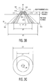
- Figures 3B and 3C are intended to illustrate that, conceptually, when the foot is lying directly on a support surface 16, without a prosthesis, it results in a narrow pressure cone (shown cross-hatched) supporting the weight W at point 11.
- the cone extends between 101 and 103 and at the outer skin level 21, the cone diameter extends between points 201 and 203.
- the final diameter of this narrow "pressure cone" along a plane 21 corresponding to the outer skin layer would be d1, having a surface area corresponding to the showing of the circle with diameter d1 in Fig. 3C .
- An important aspect of the invention is the recognition that using a protective device, such as 20, to distribute the weight present at a certain bony prominence (e.g., 11) over a greater area and volume, can significantly reduce the pressure at the interface between the bony prominence (e.g., 11) and the underlying soft tissue, across the soft tissue, and the interface between the outer skin and the protective device.
- a protective device such as 20
- the thickness and shape of the protective device 20 may be increased by selected amounts so as to reduce the pressure at the bone-soft tissue interface to less than certain predetermined levels.
- the comfort of the individual using the prosthesis may be considered in determining the thickness and size/shape of the prosthesis.
- the thickness of the section 17a underneath the foot, to the left of the heel section raises the end of bone 15 connected to point 11, tending to shift some of the weight away from being concentrated at or about point 11 back and along a portion of the leg which can safely carry a greater amount of weight, because of the thickness of the body part and the increased surface area.
- an important aspect of the protective device embodying the invention is that the weight exerted at a certain point of the body is redistributed at that local point of the body, by increasing the area (and volume) over which the weight is distributed, rather than being shifted from the point in the body where the pressure is "felt" to another point. This ensures that any pressure problem is resolved at its point of origin, rather than being shifted to another location, with uncertain consequences.
- prostheses embodying the invention may be made of many different materials having different softness/hardness features which affect, among others, the thickness of the prosthesis and the extent to which the inner surface of the prosthesis has to conform to the outer shape of the body part to provide best results.
- Fig. 3A illustrates that the prosthesis 17 could include, for example, a tapered region 17d to ensure that there are no sharp edges that might prove uncomfortable to the individual outfitted with the prosthesis of the invention.
- prostheses made in accordance with the invention may be shaped to avoid bumps and sharp edges and provide smooth and continuous transitions.
- Fig. 4 illustrates that the protective device, 20a, need not cover the top half of the foot, ankle and leg. However, the prosthesis would still protect the heel and the ankle of an individual lying on his/her side. If protecting the ankle is not a concern, the protective device can be cut back so it does not extend so high around the foot.
- Figs. 5A, 5B and 5C illustrate various prostheses for protecting the heel and the ankle when the individual either is lying down on his back or on his/her side and attachment means for holding the prostheses in place.
- a material attached to the prosthesis could include any suitable closure mechanism to hold the prosthesis in place.
- straps attached to selected points of the prosthesis may be used to hold it conformably and comfortably in place.
- a boundary region would be included around the periphery of the prosthesis, which perimeter region could include pressure sensitive adhesive in its interior surface for securing the prosthesis to the foot of an individual.
- Fig. 6A shows a top view of a simplified representation of a cushion/pad prosthesis 20b embodying the invention.
- the article 20b is formed of a rectangular piece of foam having a length, L1, a width, W1, and a thickness, t1.
- the article 20b is symmetrical about a central axis 65 running along the length of the article between the two outer sides.
- a central axis 65 running along the length of the article between the two outer sides.
- the cutout may be shaped to fit the user's foot, either exactly or approximately.
- the cutout i.e., the inner surface of the prosthesis
- the material with which the pad is formed is hard, or relatively hard
- the material is soft, it is not so important because the softer material may have sufficient deformability ("give") at low pressures to provide good contouring for the foot without introducing a significant back pressure.
- the cut outs 61 and 63 would leave a profile of the type shown in Fig. 6B and the foot of a user would rest within the prosthesis as shown in Fig. 6C .
- a rectangular prosthesis with a sculpted section in accordance with Figs.6A, 6B and 6C was made using a mushy foam (i.e., a foam having a stiffness modulus of 82.7 kPa (12 psi) and a density of 17.6 kg/m 3 (1.1lbs/ft 3 ) with a length,L1, of 203 mm (8 inches), a width,W1, of 165 mm (6.5 inches) and a thickness, t1, of 76 mm (3 inches).
- a mushy foam i.e., a foam having a stiffness modulus of 82.7 kPa (12 psi) and a density of 17.6 kg/m 3 (1.1lbs/ft 3 ) with a length,L1, of 203 mm (8 inches), a width,W1, of 165 mm (6.5 inches) and a thickness, t1, of 76 mm (3 inches).
- the cutout for the heel region was approximately 63 mm (2.5 inches) in diameter and the semi-cylindrical cutout for the leg region had a width of approximately 51 mm (2 inches). The depth of the cutouts ranged from 51 mm (2 inches) to 32 mm (1.25 inches).
- the pressure measured at the bone-soft tissue interface was equal to 2.7 millimeters of Hg. It is believed that this pressure level is so low that it will prevent the development of any pressure ulcer at the heel/ankle region and/or will enable any existing pressure ulcer at the heel/ankle region to be cured, regardless of the physical condition of the user.
- the dimensions of the prosthesis may be changed.
- the portionX1+X2 of the cushion 20b (shown in Figs. 6A-6C ) extending beyond the bottom of the foot was reduced from 51 mm (2 inches) to an X1 of less than 25 mm (one inch).
- the width W1 of the cushion was reduced (i.e., Wa and Wb were decreased) from 165 mm (6.5 inches) to less than 114 mm (4.5 inches).
- the thickness of the cushion was reduced to less than 76 mm (3 inches).
- the cutout and height of the cushion may be such as to cover the ankle, whereby if, and when, the user turns on a side, the padding will protect the soft tissue underlying the ankle bone area.
- protection for the ankle area is obtained while providing a comfortable soft layer between the ankle area of either one or both of the user's feet and any support surface.
- Applicants' invention is directed to means for redistributing the weight over as large an area as possible.
- the heel region is not made to float free which would transfer the weight of the body part to another point or region of the body.
- the weight of a body part is distributed via a protective device which covers the entire surface area and volume of the body part being protected.
- the high pressure areas of the body e.g., 11 to 21 of the heel, as shown in the various figures
- the prosthesis which distributes the weight and reduces the pressure in, and at, that region.
- Any prosthesis embodying the invention may be formed by using a mesh or mesh-like material so long as this material provides good contact to the surface area to be protected and is effective in distributing the overlying weight.
- a mesh-like material may be beneficial in enabling the skin and any dressing to "breathe".
- a prosthesis 20c may be formed having a cylindrical shape as shown in Fig. 6D .
- the cylindrical shape of the prosthesis of Fig. 6D may be modified as shown in Fig. 6E to include sections 61a and 61b which would function to stabilize the position of the foot while providing additional weight distribution along the sides of the foot, ankle, heel and leg.
- the prosthesis 20c may include an additional section 61c to make the protective device thicker. Increasing the thickness may be appropriate to provide greater pressure relief if needed by the user. This additional section could be made part of the original device or may be attached thereto in any suitable manner.
- Another aspect of the invention is the recognition that where the prosthesis is made of a soft material, the firmness of the support surface on which the foot (or other body part) rests affects the weight distribution. That is, the recognition that the entire system to be considered extends from the bony point (seeing the greatest weight concentration) to and through the prosthesis and to and through the support surface. All these considerations may be factored in the design and prescribing of a prosthesis for any particular individual
- the thickness and softness of the soft tissue and the prosthesis material between the bony prominence and the skin mattress interface affects the actual pressure experienced by the soft tissue at the bony prominence.
- the size (volume) of the protective device as well as the material out of which it is formed are significant.
- the thickness of the protective device may be varied (i.e., increased) to decrease the pressure at the bone-soft tissue interface.
- Fig. 13B is a graph of the pressure at the bone-soft tissue interface as a function of the thickness of a protective device placed between the heel/ankle and the supporting surface 16.
- the results shown in Fig. 13B were obtained by sensing the pressure at the heel point (see Fig. 13A ) of a mannequin whose foot was placed on top and/or within a prosthesis of the type shown in Figs. 6A-6C .
- a 51 mm (2 inch) diameter circle hole was sculpted out of the padding to a depth of approximately 13 mm (0.5 inch).
- the particular material used for these tests was a mushy foam having a stiffness modulus of 82.7 kPa (12 psi) and a density of 17.6 kg/m 3 (1.1lb/ft 3 ).
- Fig. 13B illustrates results when the thickness of the prosthesis had a cutout and when there was no cutout. The cutout simulates a condition of greater conformability between the prosthesis and the body part being protected.
- a prosthesis may be prescribed which will ensure that the likelihood of developing a pressure ulcer is virtually nil.
- the protective device may be made in several sizes (e.g., small medium, large) and may also be made so that its thickness may be increased by attaching various layers.
- Prostheses embodying the invention may be made of different shapes, thicknesses and materials to accommodate different individuals.
- the heel region is marked by a bony prominence and a thin soft tissue layer between the bony prominence and the outer skin layer. This renders the region subject to pressure ulcers.
- some individuals may have a very thin soft tissue layer at that point rendering them even more susceptible. For these individuals the prosthesis would have to be made thicker.
- Equipment to measure the thickness and or thinness of the soft tissue layers underlying a bony prominence of the various body parts may include, for example, X-rays, CAT scans, MRIs, ultrasound or any other suitable diagnostic tool.
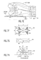
- Figure 7A is a top view of the skeletal structure showing the bony prominence 81 of the trochanter and the relatively thin soft tissue layer between the bony point 81 and the corresponding outer skin layer 91.
- Figure 7B is a blow up of the trochanter region to illustrate the bony prominence of the trochanter and the thinness of the underlying soft tissue region.
- Figure 7C illustrates what occurs at the trochanter region when an individual lies on his/her side on top of a support surface, the weight of the body overlying the trochanter is concentrated to a great extent over a small region abutting the bony prominence 81. Consequently, as shown in Fig.
- a significant weight, W is applied to a small region 81 (arc 801 to 803) and the weight is exerted over a small "pressure cone” like region (shown hatched in Fig. 7D ) having a diameter at the surface 16 extending from point 901 to 903.
- Fig. 7E illustrates the placement of a prosthesis 200 between the trochanter region and a support surface 16.
- the protective device 200 functions to distribute the weight over a much larger area and volume as schematically illustrated in Fig. 7H .
- the weight W is now effectively distributed over a much larger region as denoted by arc 811 to 813 in region 81 at the interface between the bony prominence 81 and the underlying soft tissue layer.
- the overlying weight is distributed over a much larger region (as denoted by arc 911 to 913) at the interface between the outer skin layer and the interface with the protective device 200.
- the protective device enables the weight to be distributed over a still greater region as denoted by length 211 to 213 at the interface of the protective device 200 with the support surface 16.
- the "pressure cone” subtending the full weight in the absence of the protective device is shown as a hatched cone having a final diameter d1, in Fig. 7H .
- a protective device or prosthesis 200, suitable for the trochanter area may be a soft material sculpted pad as shown in figs. 7F and 7G .
- the device 200 is shown to have a width B1, a length L1, and a thickness t2; where the range of the width, B1, can vary from within, or at, the dimensional envelope of the actual trochanter to the full side width, or more, of the user; and where the range of the length, L1, can vary from within, or at, the dimensional envelope of the actual trochanter to the full side length of the user.
- the thickness t2 may be varied to provide the desired pressure relief.
- the protective device 200 may include a pad having a central cut out of general diameter B3 shaped to enable the trochanter (and possibly the hip) area to be comfortably placed therein, with the thickness of the pad being sufficient to decrease the pressure to a desirable level.
- the protective device 200 may include cutouts 221 a, 221 b along the leg or upper thigh region.
- the protective device 200 may include cutouts 223a, 223b for the hip region.
- the protective device 200 may be attached to the body in several different ways.
- a prosthesis 200 may be attached around each leg or thigh by straps or meshing or adhesive akin to the showing of Figs. 5A-5C .
- a prosthesis 200 for each side of the body, or for both sides, could be secured by means of a belt like strap going around the body.
- Fig. 7I shows a cutaway view of the trochanter highlighting the bony prominence 81 and the thin soft tissue layer between bony point 81 and corresponding skin layer 91.
- Fig. 7I also shows a rear view of a soft material prosthesis 200a extending underneath the trochanter region of a body lying on its side and extending around the back.
- the protective device 200a would extend underneath the body, as discussed above, to reduce the pressure at the interface between the bony prominence 81 and the soft tissue layer and across the soft tissue layer, the outer skin and at the interface between the outer skin and the prosthesis 200a.
- the lateral portion 248 of the prosthesis 200a intended to be placed below the trochanter region, may extend for the full length and width of the hip section of the body, or only for a small section under the trochanter; while the upright section 250 extending above the horizontal may extend partly or wholly around the body part.
- the prosthesis may include a recessed region 249.
- the inner surface of the prosthesis 200a may be shaped to conform to the shape of the trochanter and hip area as shown in perspective in Fig. 7L .
- the prosthesis may be made with straps for attachment to the body.
- the prosthesis may wrap symmetrically around the trochanter region of the body.
- the thickness of the active area of pressure re-distribution of the prosthesis may vary in several ways.
- the thickness in the region where the pressure from the bony prominence is being distributed will vary inversely with the thickness of the skin and underlying soft tissues of the person (patient). Therefore, if the soft tissue is very thin, the thickness of the prosthesis will be greater than if the soft tissue is thick.
- the prosthesis may be as thin as 1 mm and as thick as 100 mm.
- the thickness in the region where the pressure from the bony prominence is being distributed will vary directly with the actual pressure load to be distributed (PLD). Therefore, if the PLD is very high, the thickness of the prosthesis will be greater than if the PLD is low.
- the prosthesis may be as thin as 1 mm and as thick as 100 mm.
- the thickness of the prosthesis in the region of the body surrounding the active area of pressure re-distribution is designed to provide a comfortable structure for the patient without compromising the pressure re-distribution function of the active area.
- a tapering means may be employed to gradually bring the prosthesis structure from the thickness of the active area to being flush with the skin surface of the patient.
- Figures 2A , 3A , 4 , 7E, 7F, 7G show a prosthesis construction based on this concept.
- the active areas may overlap. In that case, there may be a direct change in thickness over one active area with no surrounding areas in between. Then, any gradual thickness change would occur on the areas surrounding all the active areas in question. Again, this is generally shown in Figs. 2A , 3A , 4 and 7E-7G .
- a soft prosthesis embodying the invention may be formed of any material which enables the re-distribution of the overlying weight.
- materials from which the "soft" prostheses, discussed above and the ones to be discussed below, may be constructed include, but are not limited to, open-cell foams, closed-cell foams, gels, soft elastomeric non-foam polymers and fleeces. Also included are constructions using more than one material.
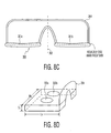
- ISCHIUM -- Figure 8A includes a rear view and Fig. 8B includes a cross sectional view of a person sitting on a protective device 300 made of a soft material (e.g., a "mushy foam"). These figures include a cut away of the ischium of the sitting person.
- the bony prominence region 181 of the ischium overlies a soft tissue layer resting on an outer skin portion 191 which rests on a layer 301 a of device 300; where the layer 301a rests on a support surface (e.g., chair or bed).
- the prosthesis may be symmetrical about a central axis 302, each side (301a, 301b) of the prosthesis being designed to carry its respective body part.
- the prosthesis includes a portion extending for a predetermined length Lx, with a width Wx and a thickness Tx with recesses 303a, 303b conforming generally to the shape of the ischium.
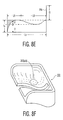
- FIG. 8E is an elevation diagram of the prosthesis.
- Fig. 8F is a perspective view of a single piece prosthesis using a soft material for simultaneously protecting the left and right ischial regions.
- Note region 303(a, b) may be recessed to conform to the extension of the ischium while being thick enough to provide good weight distribution. Consequently, the pressure at the interface between the ischium and its corresponding soft tissue layer may be maintained below a predtermined level.
- the protective device shown in Figs. 8C-8F includes a back and side portion. It should be noted that, instead, a much simpler structure comprising a circular or elliptical pad of sufficient thickness could be attached below each ischium to provide the desired pressure relief.
- FIG. 9A is a cross-sectional cut away view and Fig. 9B is a rear view of the coccyx region showing the bony prominence 281, the adjoining soft tissue layer and the corresponding outer skin region 291.
- a soft material protective pad 400 may be attached to the outer skin region to reduce the pressure at the bony prominence-soft tissue interface and across the soft tissue layer to less than a predetermined level.
- FIG. 9C is a cross sectional cut away view of a sacrum region showing the application of a "soft" prosthesis 700.
- a blow up of the sacrum region is shown in Fig. 9D illustrating a bony prominence 781, an intervening soft tissue layer 785, and a corresponding outer skin layer with contact area 791.
- Figure 9E is a perspective view of the soft prosthesis 700 with a notch 711 for conforming to the sacral region.
- the prosthesis 700 may be attached in many ways, discussed above and below.
- the protection for the sacrum differs somewhat from the protection needed at other body sites in that a shear component, as well as the pressure component can play a part on the loading at the bony prominence 781 soft tissue 785 interface and at the soft tissue to outer skin 791 interface. This is especially so when the upper part of the person's body is elevated on a bed or reclining chair.
- the shear vector acts at 90 degrees to the compression (pressure) vector. Therefore, the resultant force is at an angle between the shear and compression.
- the compression vector and its reduction would be treated by the prosthesis in a similar manner as for the other sites.
- the shear vector and its reduction are treated by allowing the external surface 713 of the prosthesis to deform, or otherwise reduce, the shear loading on the soft tissues and allow the friction load to be dissipated at the external surface 13.
- the shear vector may be distributed more effectively with a prosthetic material at its outer surface 713 having some elastomeric or viscoelastic elastic behavior allowing the prosthesis to deform rather than the outer skin and the soft tissue layer.
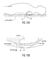
- FIG. 10A is a cross sectional cutaway view of a scapula (shoulder bone) of an individual lying on a support surface showing the bony prominence 381 and the corresponding point 391 on the outer skin.
- Fig. 10B is a blowup of the scapula section showing the placement of a "soft" protective device 500 between the scapulae region and the support surface to reduce the pressure at the bony prominence-soft tissue interface and across the soft tissue layer to less than a predetermined level.
- FIG. 11 is a cross sectional cutaway view of a soft material prosthesis 600 suitable for protecting the back of the head skull bone (occiput) of a user.
- Prosthesis 600 may be shaped like a hemisphere with a cut-out (recess) to accommodate the skull bone.
- the protective device may be attached to the body by a hair net, straps, an adhesive, or any other suitable attaching means.
- FIG.12 is a cutaway view of the elbow showing the bony prominence 481, the adjoining soft tissue layer and the corresponding outer skin region 491.
- Fig. 12 also shows a cross sectional view of a soft material prosthesis 800 suitable for use with the elbow.
- the prosthesis may be banana shaped to provide support for the elbow while enabling the user to extend to extend his/her arm.
- This protective device may be attached to the body by straps, an adhesive, a mesh, or any other suitable attaching means.
- prostheses embodying Applicants' invention may be applied to reduce the pressure associated with any bony prominence or region of concern.
- the prosthesis was made of soft, compliant material.
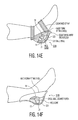
- a protective device 320 may be formed, as shown in Figs. 14A-14D , with a "hard" shell conforming to the body part to be protected.
- a hard shell prosthesis isolates, to a great extent, the body part from the support surface while, if conforming, providing extensive distribution of the body weight over a large surface area.
- the shell may be a plaster cast of the body part (e.g., the heel).
- the shell defines one layer 321 of the prosthesis and it is the inner surface of this layer 321 which is designed to conform with a high degree of fidelity to the shape of the heel (or any other body part) which it is intended to protect.
- a liner 323 may be formed and placed on top of the inner surface of the shell 321. The liner functions to smooth out certain parts of the "hard" shell which do not conform precisely and to provide a soft interface.
- the liner may be made of a "soft" substance including a soft dressing such as a hydrocolloid dressing, presently used to treat pressure ulcers.
- the liner may be made of other materials such as silicone gel, a foam, or the alginate materials used by dentists when making impressions for dentures.
- the prosthesis 320 with or without a liner 323, may be applied directly to a person's (patient's) skin; or over clothing ( as is the case for the soft prosthesis).
- the prosthesis may be secured with adhesive, straps, netting, bandage wraps, dressing, or in the case of the heel, with a stocking sleeve (as is the case for the soft prosthesis).
- An advantage of the "hard" prosthesis is that it can be made relatively thin and less bulky and the liner, if used, can also be made relatively thin.
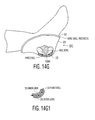
- Fig. 14C is intended to illustrate that where the prosthesis conforms to the shape of the heel and ankle the weight of the overlying body part is distributed over a large area, thus reducing the likelihood of the development of pressure ulcers.
- Fig. 14E is a perspective view of a "hard" shell prosthesis 320a mounted on a heel and a cut away view showing the heel bone 14, the heel point 11, an intervening soft tissue layer and the corresponding skin layer point 21.
- the inner surface of the shell wall 321 is form fitting and is made of a hard material.
- a liner 323 is located between the inner surface of the shell 321 and the outer skin layer. The shell may be secured to the body part by cushioned straps and the upper edge of the prosthesis would be turned away form the body.
- Fig. 14F shows a hard shell prosthesis 320b mounted directly on a heel; i.e., without a liner.
- Prosthesis 320b may be formed like prosthesis 320a, except that a liner is not included.
- Fig. 14G shows a hard shell prosthesis 320c mounted on a heel.
- the prosthesis of Fig. 14G may be like the ones of Fig. 14E or 14F , except that a soft outer layer 325 is formed on the outer portion of the hard shell 321 to prevent damaging other body parts with/by the hard shell prosthesis.
- the soft outer layer may be formed with all hard shell prostheses.
- the soft outer layer may also function to decrease shear and frictional forces.
- FIG. 15A shows a hard shell prosthesis 420 for use with the trochanter, whose inner surface is designed to conform with a high degree of fidelity to the overlying body part.
- Fig. 15A includes a cut away view of the bony prominence 81, the intervening soft tissue layer and the corresponding contact point 91.
- the weight of the overlying section is distributed over a large surface area, reducing any high pressure points.
- the protective device 420 includes an outer shell 421 and may be formed with a liner 423 or have a liner attached to the inner surface of the shell 421.
- Fig. 15B is a perspective view of a hard shell prosthesis 420a shaped to conform to the trochanter and hip area of a user.
- a liner 423 would be used to provide better continuous contact.
- Fig. 15C is a cross sectional view of a hard shell prosthesis 420b which would extend or wrap around the hip/trochanter region.
- the prosthesis 420b may include a liner 423, as discussed above.
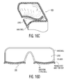
- Fig. 16A is a rear view and Fig. 16B is a cross-sectional view of a hard shell prosthesis 430 for use with the ischium of a user, shown in a sitting position.
- the figures also shows a cut away view of the ischium with the bony prominence 181, the intervening soft tissue layer and the contact point region 191.
- the weight distribution is spread over a large surface area.
- Fig. 16D is an anterior view of a hard shell prosthesis 430 highlighting that the protective device may include a hard shell 431 with a liner 433 and have a backing section so as to go around the back of the user.
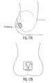
- HARD SHELL FOR COCCYX -- Figs. 17A and 17B show, respectively, a cross sectional view and a rear view of the coccyx region of an individual and a hard shell prosthesis 450 with a liner attached to that area of the body.
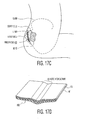
- HARD SHELL FOR SACRUM - Fig. 17C is a cross-sectional view of the sacrum to which is applied a hard shell prosthesis 460 having an outer shell 461, an inner liner 463, and a notch 465 conforming to the sacrum, as shown in Fig. 17D .
- This prosthesis is also intended to protect the user against shear forces as described above for the soft prosthesis ( Figs. 9C-9E ).
- FIG. 18A is a cross sectional cut away view of a scapula with a hard shell prosthesis 470 placed between the scapula and a support surface.
- Fig. 18B is a blow up of the scapular section showing the conforming hard shell layer 471 and a soft liner section 473.
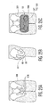
- HARD SHELL FOR OCCIPUT -- Fig. 19 is a cross sectional cut away view of the occiput (similar to Fig. 11 ) with a hard shell prosthesis 480 placed along the back of the head.
- prosthesis 480 may include a conforming hard shell 481 and a soft material liner 483.
- HARD SHELL FOR ELBOW -- Fig. 20 shows a cross section of a hard shell prosthesis 490 for use with the elbows.
- the prosthesis includes a hard shell 591 made to conform to the contour of the elbow of the user and a liner 593 made of soft material.
- the liner may be a wound dressing material or any soft matter capable of easily conforming to the shape of the body part.
- the thickness of the liner may vary over a wide range while still providing the benefit of the high degree of conformal contouring of the underlying hard shell prosthesis.
- FIGS. 24A-24E are various views of the knees and of a soft prosthesis 850 for protecting the knee cap and both the inside and the outside portion of each knee.
- Fig. 24A is a side view of a knee showing a bony prominence 881 associated with the knee cap a corresponding outer skin region 883 and an intervening soft tissue layer 885.
- Fig. 24B is a front view of the knee of Fig. 24A , showing bony prominences 861 a, 861 b, corresponding outer skin regions 871 a, 871 b, and intervening soft tissue layers 863a, 863b.
- Figs. 24C and 24D show a soft material prosthesis 850 suitable for protecting the kneecap and both sides of the knee.
- Fig. 24D is a perspective view of the prosthesis 850 including straps for attaching the prosthesis to the body.
- Fig. 24E is a cross section through the prosthesis and the knee section showing that the prosthesis protects the kneecap region as well as both sides of the knee.
- Figs. 24F , 24G, and 24H show the application of a hard material prosthesis 890 to protect the kneecap region and both sides of the knee.
- the prosthesis as shown in Fig. 24H , may include a thin, hard shell 891 and an inner liner 893.
- the hard shell prosthesis 890 would be made to conform to the shape and contour of the knee region even though, for reason of simplicity, this is not shown in the drawings.
- the hard shell prosthesis would be, or may be, hinged to enable movement of the user's legs. If needed, the hinging may be incorporated in the soft material prosthesis 850.
- Figs. 25A and 25B are, respectively, a rear view and a side view of the buttocks showing a bony prominence 981 an outer skin region 983 and an intervening soft tissue layer 985.
- Figs. 25C and 25D show the application of a soft material prosthesis 950 to the buttocks region so as to reduce pressure between regions 981 and 983.
- Figs. 25E and 25F show the application of a hard shell prosthesis 990 conforming to the region 983 to reduce the pressure between regions 981 and 983.
- the individual protective devices thus far developed for the external application to the body parts may be clustered to include all of the locations of interest.
- securing these units to assemblies as described below a system can be attained that gives each patient the level of protection from high pressures that he or she needs.
- These protective devices can be secured to stockings, panty hose, panty, shirt or body suit either within the garment or be affixed to the outside of the garment.
- Garment constructions can be used that have flaps at the critical locations which may be opened for insertion of a prosthesis.
- Assemblies suitable for enabling the application/attachment of more than one prosthesis at a time include, for example:
- the prostheses concepts thus far considered are based on using materials which maintain stable compression properties during their usage. Applicants recognized that there is a relationship between the stiffness of the material used and the thickness of material required to achieve desired pressure reduction at the sites of interest. This relationship is that the stiffer the (conforming) material, the thinner the prosthesis required to achieve the desired results.
- the site receiving the treatment cannot differentiate which prosthesis is being used to reduce the bone-soft tissue interface
- the material can have a dry, stiff structure that can be in sheet, powder and other forms consistent with firm dry materials. Such materials may also be formed into shapes that can be contoured around other shapes such as the body sites where pressure ulcers form.
- the "fluid" may also be a gas, such as air.
- a prosthesis may be constructed from a relatively rigid compressed foam elastomer, which is pre-shaped to the contour of a body site and then applied. As the patient (person) wears the prosthesis, the temperature of the patient may cause the foam to expand and become softer and thicker to provide pressure reduction.
- Figures 21A-21D show the operation of such a device on a site of concern, the heel. It serves only as an example and this invention can be applied to all sites of interest.
- Fig. 21A is a cross section of the heel ankle region.
- Fig. 21B illustrates the application of a "stiff" prosthesis below the heel region which runs continuously below the bottom of the foot.
- the stiff prosthesis is made to conform to the shape of the body part.
- this prosthesis is made of the materials identified in (a)-(e), above, or in similar materials exhibiting like characteristics. Note that the thickness of the prosthesis both below the heel and below the foot is made relatively thin.
- the exterior portion of the prosthesis may include a barrier which inhibits any fluid from escaping. [Note: the fluid present and being absorbed may be due to medication (wound dressing) or due to moisture emitted by the body]. Therefore, any fluid at the body part will be absorbed by the prosthesis.
- Fig. 21C shows the expansion of the thickness of the prosthesis as it absorbs fluid. As the prosthesis expands (i.e., becomes thicker) it also becomes softer and more compliant to the overlying body part whose weight is exerted onto the prosthesis, providing more area and volume to absorb the weight of the body part.
- Fig. 21D shows that the prosthesis may have expanded significantly, absorbing the fluid being emitted by or around the body part, while providing pressure relief to the all parts of the body part being protected
- the thickness and softness of the soft tissue(s) between a bony prominence and the skin-mattress interface greatly affects the actual pressure experienced by the soft tissues at the bony prominence(s). As the weight and pressure radiate from the bony prominence towards the skin-mattress interface, the pressure at the bony prominence is reduced, and a greater reduction is experienced if the soft tissue is thicker and softer. Therefore, if a prosthesis embodying the invention consists at least, in part, of a "soft tissue" extension at the sites of concern, then the pressure at the bony prominence will be reduced.
- mushy foam samples were prepared having rectangular surfaces of 152 mm ( 6 inches) by 178 mm (7 inches) and with thicknesses varying from 13 mm (0.5 inches) to 63 mm (2.5 inches). These samples were then applied to a mannequin to measure, with a sensor, changes in the internal heel pressure of the mannequin. The polymer thickness at the heel of the mannequin was 13 mm (0.5 inches). [Note: In practice, these measurements of thickness would be made on a live patient, instead.] the following test were performed:
- FIG. 13B shows the internal pressure at the heel bone as a function of the thickness of a soft foam protective device.
- Each soft foam pad is a 152 mm (6 inch) by 178 mm (7 inch) rectangle cut to the thickness specified. It was placed on top of a firm foam mattress and the internal heel bone pressure was measured. A cutout was made in the sample having 5 centimeter diameter circle and being 1.25 cm deep (approximately 0.5 inches). The heel was placed in the cutout for these tests. For the 13 mm (0.5 inch) thick sample, making a cut out of 13 mm (0.5 inches) created a doughnut-like sample.
- prostheses embodying the invention do not rely on a doughnut effect to provide pressure reduction and weight redistribution.
- test results indicate that better (lower pressure) results are obtained with cut outs. This is because there is greater surface area contact for this condition.
- the findings from this study confirm that a 51 mm (2 inch) thick mushy foam sample with a cutout can reduce the internal pressure at the bony prominence-soft tissue interface to an acceptable range to prevent pressure ulcer formation or allow an existing pressure ulcer to heal without patient turning.
- the sample and like devices can be incorporated as a prosthesis into, or onto, a dressing for treating such wounds where they already exist or become a prosthesis for the prevention of the ulcers in the first place.
- the mushy foam is very cheap and very easy to process into the shapes and thicknesses required to serve as an effective prosthesis. This allows protective devices embodying the invention to be a disposable item which may be sterilized if in use as part of a dressing, or to be non-sterile if in use to prevent ulcer formation.
- compliant load bearing mediums may be considered as a composite structure for supporting the skeletal frame.
- This composite support structure comprises three components: (a) the patient's soft tissue against which the skeletal system (bone) comes into contact; (b) the protective device (prosthesis) which is interposed between the outer skin layer and the base support structure (i.e., bed mattress); and (c) the base (mattress or chair) which ultimately supports the overlying weight of the patient and prosthesis.
- the design of a soft prosthesis may include the compliance (softness) of the load bearing base (bed or chair) and the prosthesis itself as an integral part of the patient's soft tissue. If the load bearing base is non-compliant (hard), the prosthesis and the patient's soft tissue must distribute all the load within this volume so as to reduce the pressure seen at the bony prominence to less than a predetermined value (e.g., 32 mm Hg). If the load bearing base is compliant (soft), the compliance may be taken into account when calculating the load distribution characteristic of the overall composite structure. A more compliant base provides for some pressure distribution which results in a prosthesis design requiring less material volume and thickness. However, in most instances the prosthesis is designed assuming the base support to be non-compliant.
- FIG. 23A shows a portion of a leg amputated above the knee.
- the lower region may be outfitted with a soft prosthesis 903 as shown in Fig. 23B or with a hard prosthesis as shown in Fig. 23D .
- the bone section 911 1 may be effectively widened by the addition of an implant 913 to the bone section increasing the contact area of the bone section overlying the leg/foot support 914, as shown in Fig. 23C .
- a prosthesis 915 with increased thickness and areas may be attached to the region 901 and bone 911 to provide greater area and volume to reduce pressure.
- FIGS 22A-22D show how a prosthesis 2001 would be installed around the trochanter, between the soft tissue layer underlying and surrounding the trochanter and the inner surface of the corresponding skin layer.
- the protective device 2001 would be installed around the trochanter between the trochanter and the underlying soft tissue layer.
- the implant 2001 could be a soft material or a hard material.
- a hard material implant could be used to effectively increase the surface area of any bony prominence so as to reduce any "sharp" bony points, as shown, for example in Fig. 23 .
- the various prostheses and prosthetic devices embodying the invention may include, or be entirely formed of, a "medicated” (or “non-medicated") dressing or material containing various substances to also provide “medical” protection and/or healing to the body part to which the prosthesis is attached.
- a "medicated” (or “non-medicated") dressing or material containing various substances to also provide “medical” protection and/or healing to the body part to which the prosthesis is attached.
- the entire prosthesis particularly where it is a "soft" prosthesis, may be constructed of material which may include a dressing or layer containing various substances to further protect the body part to which the prosthesis is attached.
- the entire prosthesis or a dressing or layer on, or within, the prosthesis may include or consist of: (a) a dressing or a medicated dressing; (b) a hydrocolloid dressing by itself or containing medication including one or more of an antibacterial, anti-inflammatory, anti-fungal, and/or a pain killing substance; (c) a hydrogel by itself, or containing medication including one or more of an antibacterial, anti-inflammatory, anti-fungal, and/or a pain killing substance; (d) a thin film dressing by itself and/or containing medication including one or more of an antibacterial, anti-inflammatory, anti-fungal, and/or a pain killing substance; (e) a gauze dressing by itself and/or containing medication including one or more of an antibacterial, anti-inflammatory, anti-fungal, and/or a pain killing substance; (f) a non- woven dressing by itself and/or containing medication including one or more of an antibacterial,
- prostheses themselves, or layers of materials added to the prostheses, may incorporate substances providing for tissue seeding, tissue incorporation and tissue growth.
- the weight of a body part or the body illustrates one type of load which can lead to pressure ulcers.
- Other types of loads that can lead to pressure ulcers include, for example, tight fitting shoes and prosthetic devices, such as an artificial arm or leg, which is too tightly (or improperly) connected to a limb of an amputee. Shear forces as well as compression forces and a combination of these forces can lead to pressure ulcers.
- Fig. 26 shows a graph of critical pressure as a function of time the body part is exposed to the pressure.
- a pressure of 220 mm of Hg applied for 1-2 hours at a certain site will cause a pressure ulcer to develop.
- a pressure of 40 mm of Hg to be applied for 6 hours to cause a pressure ulcer to develop at that site.
- the pressure is less than 20 mm of Hg, it would take at least 15 hours for this pressure to cause a pressure ulcer.
Landscapes
- Health & Medical Sciences (AREA)
- Public Health (AREA)
- Engineering & Computer Science (AREA)
- Heart & Thoracic Surgery (AREA)
- Vascular Medicine (AREA)
- Life Sciences & Earth Sciences (AREA)
- Animal Behavior & Ethology (AREA)
- Biomedical Technology (AREA)
- Veterinary Medicine (AREA)
- General Health & Medical Sciences (AREA)
- Materials For Medical Uses (AREA)
- Prostheses (AREA)
- Steroid Compounds (AREA)
- Surgical Instruments (AREA)
- Macromonomer-Based Addition Polymer (AREA)
- Professional, Industrial, Or Sporting Protective Garments (AREA)
Claims (65)
- Schutzvorrichtung zum Schützen eines Teils eines menschlichen Körpers vor der Ausbildung eines Druckgeschwürs oder zum Heilen eines bestehenden Druckgeschwürs, wobei der Körperteil eine Knochenstruktur und eine Weichgewebeschicht zwischen der Knochenstruktur und einer äußeren Hautschicht, die dazu vorgesehen ist, in Kontakt mit einer Stützstruktur zu gelangen, aufweist, umfassend:ein Pad (20b, 200, 400) zur Anbringung an dem zu schützenden Körperteil, wo der Körperteil und die Knochenstruktur, die zu schützen sind, eine ossale Erhebung aufweist, welche das Gewicht (W) des Körperteils auf eine kleine Fläche (A1) konzentriert und einen Druck (P1) erzeugt, der gleich W/A1 ist, und zwar an der Schnittstelle zwischen der ossalen Erhebung undderen korrespondierender Weichgewebeschicht, wobei P1, wenn über einen Zeitraum t1 aufgebracht, geeignet ist, die Ausbildung eines Druckgeschwürs in dem der ossalen Erhebung zugehörigen Körperteil zu verursachen;wobei das Pad eine obere innere Fläche und eine untere äußere Fläche aufweist, sowie Material zwischen der oberen und unteren Fläche zur Bereitstellung einer gewünschten Dicke des Pads; (a) die obere Fläche einen Bereich aufweist, der dazu geeignet ist, einen der ossalen Erhebung zugehörigen Körperteil aufzunehmen, dadurch gekennzeichnet, dass der Bereich der ossalen Erhebung etwas entgegengesetzt und dem die ossalen Erhebung enthaltenden Körperteil angepasst ist und diesen umschließt; und (b) das Material und die untere äußere Fläche, die sich unter in den genannten Bereich erstrecken, von geeignet größerer Fläche ist als die Fläche des genannten Bereichs und die untere Fläche im Allgemeinen an die Stützstruktur anpassbar ist, um zu ermöglichen, dass im Wesentlichen das gesamte Gewicht (W) radial verteilt wird, kontinuierlich und allmählich, über einen anwachsende Fläche reichend von der ossalen Erhebung und von dem genannten Bereich zu der Stützstruktur und endend entlang der Stützstruktur, um den an der Schnittstelle zwischen der ossalen Erhebung und deren korrespondierender Weichgewebeschicht entstehenden Druck auf einen Niveau abzusenken, das wesentlich kleiner ist als P1 und kleiner als der Druck, welcher innerhalb der Zeit t1 die Ausbildung eines Druckgeschwürs in jenem Teil des Körpers verursachen würde.
- Schutzvorrichtung nach Anspruch 1, bei der die obere Fläche des Pads (20b, 200, 400) derart geformt ist, um der Form des zu schützenden Körperteils zu entsprechen, um zu ermöglichen, dass der die ossalen Erhebung enthaltende Körperteil in dem geformten Bereich positionierbar ist, und zur Vergrößerung der Oberfläche, über die das Gewicht des Körperteils und der ossalen Erhebung verteilt wird.
- Schutzvorrichtung nach Anspruch 1, bei der die obere Fläche des Padmaterials derart gewählt ist, um zu ermöglichen, dass die obere Fläche des Pads sich verformt, um sich an den die ossale Erhebung enthaltenden Körperteil anzupassen und diesen zu umgeben, um die Oberfläche, über die das Gewicht des Körperteils verteilt wird, zu vergrößern.
- Schutzvorrichtung nach Anspruch 1, bei der das Padmaterial eines aus einem elastischen Material, einem nachgiebig weichem Schaumstoff, einem im Allgemeinen nachgiebigen Material und einem Netzmaterial ist; wobei die untere Seite des Pads im Allgemeinen der Oberfläche der Stützstruktur angepasst ist, um die Fläche, über die das Gewicht an der ossalen Erhebung verteilt wird, zu vergrößern als Funktion des Abstands der ossalen Erhebung von der Stützfläche.
- Schutzvorrichtung nach Anspruch 1, bei der das Padmaterial von der Art ist, welche es der inneren oberen Fläche ermöglicht, sich an den die ossalen Erhebung enthaltenden Körperteil anzupassen und diesen zu umschließen und weiterhin der unteren Fläche des Pads ermöglicht sich allgemein an die Fläche der Stützstruktur anzupassen, um zu ermöglichen, dass der Körperteil, wenn dieser innerhalb des Pads positioniert ist, das an der ossalen Erhebung konzentrierte Gewicht über eine größere Fläche als A1 an der Schnittstelle zwischen der ossalen Erhebung und der Weichgewebeschicht verteilt, und zwar über eine Fläche, welche anwächst wie der Abstand von der ossalen Erhebung zu der Stützfläche anwächst.
- Schutzvorrichtung nach Anspruch 4, bei der die Dicke des Pads wahlweise erhöhbar ist, um den Druck an der Schnittstelle zwischen der ossalen Erhebung und der korrespondierenden Weichgewebeschicht zu verringern, und wobei der Körperteil, an dem das Pad angebracht ist, in jede Richtung frei bewegbar ist.
- Schutzvorrichtung nach Anspruch 1, bei der die Dicke des Pads zumindest 6 mm (ein Viertel (1/4) Inch) beträgt, die Länge des Pads von 6 mm (ein Viertel (1/4) Inch) bis mehr als 152 mm (sechs Inches) reicht und die Breite des Pads von 6 mm (ein Viertel (1/4) Inch) bis mehr als 152 mm (sechs Inches) reicht.
- Schutzvorrichtung nach Anspruch 1, bei der der zu schützende Körperteil zumindest einer aus Ferse, Knöchel, Trochanter, Knie, Kreuzbein, Steißbein, Gesäß, Ischion bzw. Sitzbein, Schulterblatt, Ellbogen und Occiput bzw. Hinterhaupt ist; und die innere Fläche des Pads der Form des Körperteils, der die ossale Erhebung seines jeweiligen Körperteils enthält, entspricht und die äußere Fläche im Allgemeinen an die Stützfläche anpassbar ist.
- Schutzvorrichtung nach Anspruch 7, bei der die äußere Fläche eine harte Außenschale aufweist.
- Schutzvorrichtung nach Anspruch 7, bei der die äußere Fläche eine harte Außenschale (321, 421, 431, 461, 471, 481, 591, 891) zum Schutz des Körperteils vor den Wirkungen der Stützstruktur aufweist.
- Schutzvorrichtung nach Anspruch 9, bei der die innere Fläche ebenfalls eine harte Innenschale aufweist.
- Schutzvorrichtung nach Anspruch 1, bei der das Pad aus einem weichen Material hergestellt ist, dessen äußere Fläche im Allgemeinen an unterschiedliche Stützstrukturen anpassbar ist und eine hinreichende Dicke von mindestens 6 mm (ein Viertel (1/4) Inch) aufweist, um die Drücke, welche innerhalb des Körperteils entstehen, zu verringern, um dem Körperteil, an dem das Pad angebracht ist, zu ermöglichen, für einen verlängerten Zeitraum an der Stützstruktur zu ruhen, ohne ein Druckgeschwür zwischen der ossalen Erhebung und der korrespondierenden Weichgewebeschicht des Körperteils auszubilden.
- Schutzvorrichtung nach Anspruch 11, bei der der Abschnitt der äußeren Fläche des Pads, der mit der Stützstruktur in Kontakt steht, im Allgemeinen der Form der Stützstruktur angepasst ist.
- Schutzvorrichtung nach Anspruch 4, bei der die innere Fläche des Pads der Form einer Ferse angepasst ist und sich vom Fußgewölbe zum Knöchelbereich erstreckt und der Abschnitt der äußeren Fläche des Pads, der mit der Stützstruktur in Kontakt steht, im Allgemeinen der Form der Stützstruktur angepasst ist.
- Schutzvorrichtung nach Anspruch 13, bei der das Pad derart ausgestaltet ist, um durch einen Benutzer getragen zu werden und einen Bereich abzudecken, der sich vom Fußgewölbe bis zumindest dem Knöchelbereich eines Benutzers erstreckt.
- Schutzvorrichtung nach Anspruch 1, bei der der zu schützende Körperteil die Ferse ist und das Pad sich unterhalb des Fußes und der Ferse erstreckt und die volle Breite des Fußes und der Ferse erweitert und im Wesentlichen eine zylindrische Form aufweist.
- Schutzvorrichtung nach Anspruch 1, bei der die innere Fläche des Pads sich um die Unterseite des Fußes und Knöchelbereichs erstreckt und ein Abschnitt seiner Form eines der folgenden ist: rechteckig, zylindrisch, halbzylindrisch, ringförmig, ellipsoidal, länglich, dreieckig oder eine Kombination hieraus.
- Schutzvorrichtung nach Anspruch 7, bei der jedes Pad Mittel zur Sicherung des Pads an dem entsprechenden Körperteil aufweist.
- Schutzvorrichtung nach Anspruch 3, bei der jedes Pad um den entsprechenden Körperteil platziert ist, um den Körperteil unabhängig von der Orientierung des Körperteils an oder entfernt von der Stützstruktur zu schützen.
- Schutzvorrichtung nach Anspruch 1, welche zwischen der äußeren Hautschicht und der inneren Fläche der Schutzvorrichtung zumindest eines der folgenden aufweist:a. eine Schicht Verbandmaterial;b. eine Schicht Arzneistoffe enthaltendes Verbandmaterial;c. eine Schicht Hydrokolloid-Verbandmaterial;d. eine Schicht Hydrokolloid-Verbandmaterial enthaltend Arzneistoffe einschließlich zumindest eines aus einer antibakteriellen, einer entzündungshemmenden und einer antimykotischen Substanz sowie eines Schmerzmittels;e. eine Schicht Hydrogel;f. eine Schicht Hydrogel enthaltend Arzneistoffe einschließlich zumindest eines aus einer antibakteriellen, einer entzündungshemmenden und einer antimykotischen Substanz sowie eines Schmerzmittels;g. ein Dünnschichtverbandmaterial;h. ein Dünnschichtverbandmaterial enthaltend Arzneistoffe einschließlich zumindest eines aus einer antibakteriellen, einer entzündungshemmenden und einer antimykotischen Substanz sowie eines Schmerzmittels;i. eine Schicht Verbandmull;j. eine Schicht Verbandmull enthaltend Arzneistoffe einschließlich zumindest eines aus einer antibakteriellen, einer entzündungshemmenden und einer antimykotischen Substanz sowie eines Schmerzmittels;k. eine Schicht Vliesstoff-Verbandmaterial;l. eine Schicht Vliesstoff-Verbandmaterial enthaltend Arzneistoffe einschließlich zumindest eines aus einer antibakteriellen, einer entzündungshemmenden und einer antimykotischen Substanz sowie eines Schmerzmittels;m. eine Schicht eines Schaumstoffverbandmaterials;n. eine Schicht eines Schaumstoffverbandmaterials enthaltend Arzneistoffe einschließlich zumindest eines aus einer antibakteriellen, einer entzündungshemmenden und einer antimykotischen Substanz sowie eines Schmerzmittels;o. eine Schicht aus Material, das derart ausgebildet ist, um überschüssige Feuchtigkeit und Flüssigkeit aufzunehmen;p. eine Schicht aus Material, dass eine Feuchtigkeitsdampfdurchlässigkeit zur Abfuhr überschüssiger Feuchtigkeit aufweist;q. eine Schicht aus Material, welches eine Luftdurchlässigkeit zur Ermöglichung einer Luft Zirkulation zur Abfuhr überflüssiger Wärme und Feuchtigkeit aufweist; undr. eine Schicht aus Material enthaltend Arzneistoffe einschließlich zumindest eines aus einer antibakteriellen, einer entzündungshemmenden und einer antimykotischen Substanz sowie eines Schmerzmittels.
- Schutzvorrichtung nach Anspruch 1, umfassend zumindest eines der folgenden:(a) ein Verbandmaterial;(b) ein Arzneistoffe enthaltendes Verbandmaterial;(c) ein Hydrokolloid-Verbandmaterial;(d) ein Hydrokolloid-Verbandmaterial enthaltend Arzneistoffe einschließlich zumindest eines aus einer antibakteriellen, einer entzündungshemmenden und einer antimykotischen Substanz sowie eines Schmerzmittels;(e) ein Hydrogel;(f) ein Hydrogel enthaltend Arzneistoffe einschließlich zumindest eines aus einer antibakteriellen, einer entzündungshemmenden und einer antimykotischen Substanz sowie eines Schmerzmittels;(g) ein Dünnschichtverbandmaterial;(h) ein Dünnschichtverbandmaterial enthaltend Arzneistoffe einschließlich zumindest eines aus einer antibakteriellen, einer entzündungshemmenden und einer antimykotischen Substanz sowie eines Schmerzmittels;(i) Verbandmull;(j) Verbandmull enthaltend Arzneistoffe einschließlich zumindest eines aus einer antibakteriellen, einer entzündungshemmenden und einer antimykotischen Substanz sowie eines Schmerzmittels;(k) ein Vliesstoff-Verbandmaterial;(l) ein Vliesstoff-Verbandmaterial enthaltend Arzneistoffe einschließlich zumindest eines aus einer antibakteriellen, einer entzündungshemmenden und einer antimykotischen Substanz sowie eines Schmerzmittels;(m) ein Schaumstoffverbandmaterial;(n) ein Schaumstoffverbandmaterial enthaltend Arzneistoffe einschließlich zumindest eines aus einer antibakteriellen, einer entzündungshemmenden und einer antimykotischen Substanz sowie eines Schmerzmittels;(o) ein Material, das derart ausgebildet ist, um überschüssige Feuchtigkeit und Flüssigkeit aufzunehmen;(p) ein Material, das eine Feuchtigkeitsdampfdurchlässigkeit zur Abfuhr überschüssiger Feuchtigkeit aufweist;(q) ein Material, welches eine Luftdurchlässigkeit zur Ermöglichung einer Luftzirkulation aufweist; und(r) ein Material enthaltend Arzneistoffe einschließlich zumindest eines aus einer antibakteriellen, einer entzündungshemmenden und einer antimykotischen Substanz sowie eines Schmerzmittels.
- Schutzvorrichtung nach Anspruch 1, bei der das Pad eine hinlängliche Dicke und Weichheit aufweist, um das Gewicht des Körperteils über eine ausgedehnte Fläche und ein ausgedehntes Volumen zu verteilen, um den Druck, der an der Schnittstelle zwischen der Knochenstruktur und der entsprechenden Weichgewebeschicht, über die entsprechende Weichgewebeschicht und an der Schnittstelle zwischen der entsprechenden Weichgewebeschicht und der entsprechenden äußeren Hautschicht und zwischen der entsprechenden äußeren Hautschicht und der Stützstruktur ausgeübt wird, zu verringern;
wobei das Pad so geformt ist, um die Fläche, über die das Gewicht an der ossalen Erhebung verteilt wird, zu erhöhen als eine Funktion des Abstands der ossalen Erhebung zu der Stützstruktur; und
wobei die Stützstruktur eine der folgenden ist: eine horizontale Fläche mit einem breiten Härtebereich, auf der ein menschlicher Körper ruhen kann, eine Matratze mit einem breiten Härtebereich, eine Sitzstruktur, und jegliche Prothese, die einen Körperteil ersetzt. - Schutzvorrichtung nach Anspruch 1, bei der die Größe des Pads als Funktion von Form, Größe und Gewicht des Körperteils und der ossalen Erhebung gewählt ist, um die effektive Fläche und das Volumen, über welche das konzentrierte Gewicht an der Schnittstelle zwischen dem Knochenabschnitt und der umgebenden Weichgewebeschicht verteilt wird, zu reduzieren und dadurch den Druck infolge der ossalen Erhebung, welcher an der Schnittstelle zwischen der ossalen Erhebung und der entsprechenden Weichgewebeschicht, über die entsprechende Weichgewebeschicht und an der Schnittstelle zwischen der entsprechenden Weichgewebeschicht und der entsprechenden äußeren Hautschicht und zwischen der entsprechenden äußeren Hautschicht und der inneren Fläche der Schutzvorrichtung, deren äußere Fläche dazu vorgesehen ist, in Kontakt mit der Stützflächen zu gelangen, ausgeübt wird, zu verringern.
- Schutzvorrichtung nach Anspruch 23, bei der das Material zwischen der oberen und unteren Fläche der Schutzvorrichtung von der Art ist, welche es der inneren Fläche ermöglicht, sich an den die ossalen Erhebung enthaltenden Körperteil anzupassen und diesen zu umgeben, um zu bewirken, dass das Gewicht des Körperteils über eine größere Fläche verteilt wird; und die Schutzvorrichtung um den Körperteil herum platziert ist, um den Körperteil unabhängig von der Orientierung des Körperteils an der Stützstruktur zu schützen.
- Schutzvorrichtung nach Anspruch 23, umfassend ein im allgemeinen rechteckiges Kissen mit einer Breite von mindestens 6 mm (ein Viertel (1/4) Inch) und einer Länge von mindestens 6 mm (ein Viertel (1/4) Inch) und das Material zwischen der oberen und unteren Fläche eines ist aus elastischem Material, nachgiebigem Schaumstoff, einem Netzmaterial und Materialien einschließlich jedoch nicht beschränkt auf Verbandmaterial, faserförmige Absorptionsmittel, fettartige Substanzen wie Silikon oder Wachs, Fleece, Schaumstoff, Verbandmull, Gele, Hartschalen, Hydrokolloide, feuchtigkeitsabsorbierende Materialien, feuchtigkeitsentfernende Materialien, durchlässige Materialien, Materialien welche sich in Dicke und Steifigkeit verändern können, viskoelastische Materialien und eine Kombination der vorgenannten.
- Schutzvorrichtung nach Anspruch 23 umfassend ein im Allgemeinen längliches Kissen mit einer Vertiefung, die dem ossalen Abschnitt gegenüberliegend angeordnet ist.
- Schutzvorrichtung nach Anspruch 23, welche Mittel zur Anbringung der Prothese an dem Körperteil aufweist.
- Schutzvorrichtung nach Anspruch 1, bei der, wenn der Körperteil in Kontakt mit einer Stützfläche steht, das Gewicht des Körperteils, der den ossalen Abschnitt enthält, einen Druckgradienten an der Schnittstelle zwischen dem ossalen Abschnitt und der Weichgewebeschicht, durch die Weichgewebeschicht und zwischen der Hautschicht und der Stützfläche erzeugt und die Ausbildung eines Druckgeschwürs an dem Körperteil verursachen kann; und bei der die Schutzvorrichtung eine an den Körperteil, an welchem sie angebracht ist, angepasste innere Fläche aufweist sowie eine an die Stützfläche anpassbare äußere Fläche; und die Schutzvorrichtung eine allmähliche und radiale Verteilung des Gewichts des Körperteils und des ossalen Abschnitts über eine zunehmende Fläche und ein zunehmendes Volumen ermöglicht, welche einen Druckkegel definieren, um dadurch den Druck infolge des Knochenpunktes zu reduzieren, welcher ausgeübt wird an der Schnittstelle zwischen dem ossalen Abschnitt und der entsprechenden Weichgewebeschicht, durch die entsprechende Weichgewebeschicht hindurch und an der Schnittstelle zwischen der entsprechenden Weichgewebeschicht und der entsprechenden äußeren Haut und zwischen der entsprechenden äußeren Haut und der inneren Fläche der Schutzvorrichtung, deren Außenfläche dazu vorgesehen ist, in Kontakt mit der Stützfläche zu stehen.
- Schutzvorrichtung nach Anspruch 23, bei der eine Schicht zwischen der äußeren Hautschicht und der äußeren Fläche der padförmigen Struktur vorgesehen ist, um ein Atmen der Haut zu gestatten.
- Schutzvorrichtung nach Anspruch 23, bei der die Dicke der Schutzvorrichtung wahlweise vergrößert werden kann durch Hinzufügen von Schichten zu der äußeren Fläche der Schutzvorrichtung zur weiteren Verminderung des Drucks an der Schnittstelle zwischen dem ossalen Abschnitt und dessen umgebender Weichgewebeschicht.
- Schutzvorrichtung nach Anspruch 1, zur Verwendung wenn der Druck an einem Punkt um eine ossalen Erhebung einen bestimmten kritischen Wert (Pc) übersteigt, mit dem Ergebnis, dass sich Druckgeschwüre in dem Körperteil ausbilden können, wobei die Schutzvorrichtung, die den ossalen Abschnitt des zu schützenden Körperteils einschließt und zwischen dem ossalen Abschnitt des zu schützenden Körperteils und der Stützfläche angeordnet ist, als Verlängerung der den ossalen Abschnitt umgebenden Weichgewebeschicht dient, durch eine innere Fläche, welche an den Körperteil, den sie umschließt, angepasst ist, und eine äußere Fläche, welche im Allgemeinen an die Form der Stützflächen anpassbar ist, um das Gewicht des Körperteils und des ossalen Abschnitts über eine große Fläche zu verteilen; und die Schutzvorrichtung eine ausreichende Dicke und Weichheit aufweist, um das Gewicht des Körperteils über eine vergrößerte Fläche und ein vergrößertes Volumen derart zu verteilen, dass der Druck, welcher zwischen dem ossalen Abschnitt und dem zugehörigen Körperteil sowie der entsprechenden Weichgewebeschicht, durch die entsprechende Weichgewebeschicht und an der Schnittstelle zwischen der entsprechenden Weichgewebeschicht und der entsprechenden äußeren Haut geringer ist als der kritische Wert des Drucks (Pc), der die Ausbildung eines Druckgeschwürs an dem Teil des Körpers verursachen würde.
- Schutzvorrichtung nach Anspruch 31, bei der der kritische Druck, welcher ein Druckgeschwür verursacht, eine Funktion der Zeit, über die ein vorgegebener Druck anliegt, ist, und ausgewählte Eigenschaften der an dem Körperteil anzubringenden Schutzvorrichtung einschließlich deren Größe, Weichheit und Dicke ausgewählt sind, um unterschiedliche Werte als Funktion der Zeitdauer, über die das Körperteil an der Stützflächen gelagert ist, aufzuweisen.
- Schutzvorrichtung nach Anspruch 32, bei der die ausgewählten Eigenschaften der an den Körperteil anzubringenden Schutzvorrichtung, einschließlich deren Größe, Weichheit und Dicke, so gewählt sind, um sich als Funktion der Länge der Zeitdauer, die der Körperteil an der Stützfläche verbringt, der Temperatur und der Feuchtigkeit zu verändern.
- Schutzvorrichtung nach Anspruch 31, bei der die ausgewählten Eigenschaften der Schutzvorrichtung sich allmählich verändern als Funktion der Zeit, um allmählich die Fläche und das Volumen, über die das konzentrierte Gewicht verteilt wird, zu erhöhen, um den Druck an der Schnittstelle zwischen dem ossalen Abschnitt und der Weichgewebeschicht um den ossalen Abschnitt herum sowie innerhalb der Weichgewebeschicht und an der Schnittstelle zwischen der Weichgewebeschicht und der äußeren Haut des Körperteils, an der diese angebracht ist, allmählich zu verringern.
- Schutzvorrichtung nach Anspruch 31, bei der selektive Eigenschaften der Schutzvorrichtung, nämlich zumindest eine von deren Dicke, Weichheit, Fläche, Volumen und Druckmodul, so gewählt sind, um sich als Funktion der Zeit zu verändern, um die effektive Fläche zu erhöhen und den auf die Körperteilbestandteile einwirkenden Druck zu vermindern.
- Schutzvorrichtung nach Anspruch 1, bei der das Pad den Bereich des die ossale Erhebung enthaltenden Körperteils umgibt und zwischen dem Körperteil und der Stützfläche angeordnet ist, so dass die effektive Fläche zwischen der ossalen Erhebung und der zugrundeliegenden Weichgewebeschicht gleich A2 ist, wobei A2 größer ist als A1, wodurch der resultierende Druck zwischen der ossalen Erhebung und der zugrundeliegenden Weichgewebeschicht P2 ist, welches gleich W/A2 ist, wobei P2 kleiner als P1 ist; und die Schutzvorrichtung so gewählt ist, dass P2 einen Wert unterhalb eines kritischen Werts annimmt, der geeignet wäre, Druckgeschwüre in dem Körperteil zu verursachen.
- Schutzvorrichtungssatz zum Schutz einer ausgewählten Anzahl unterschiedlicher Körperteile einer Person vor der Ausbildung eines Druckgeschwürs oder zur Heilung eines bestehenden Druckgeschwürs, wobei jeder zu schützende Körperteil einen ossalen Abschnitt mit einer Weichgewebeschicht zwischen dem ossalen Abschnitt und einer äußeren Hautschicht aufweist und der Körperteil zu schützen ist, wenn der Körperteil in Kontakt mit einer Stützflächen steht und das Gewicht des Körpers und des Körperteils die Ausbildung eines Drucks an der Schnittstelle zwischen dem ossalen Abschnitt und der entsprechenden Weichgewebeschicht, durch die Weichgewebeschicht hindurch und zwischen der Hautschicht und der Stützfläche verursacht, welcher die Ausbildung eines Druckgeschwürs an dem Körperteil verursachen kann, wobei der Schutzvorrichtungssatz umfasst:einen Satz unterschiedlicher Schutzvorrichtungen gemäß Anspruch 1 zur Anbringung an entsprechenden zu schützenden Körperteilen, wobei jede Schutzvorrichtung eine innere Fläche aufweist, die an den Körperteil, an dem diese angebracht ist, angepasst ist, sowie eine äußere Fläche, die zur Kontaktierung der Stützfläche geeignet ist; und jede Schutzvorrichtung zur Verteilung des Gewichts des entsprechenden Körperteils über eine vergrößerte Fläche zur Verringerung des Drucks an der Schnittstelle zwischen dem jeweils entsprechenden ossalen Abschnitt und der entsprechenden Weichgewebeschicht dient.
- Schutzvorrichtungssatz nach Anspruch 37, umfassend eine Reihe von Schutzvorrichtungen unterschiedlicher Größe für den gleichen Körperteil zur Anlage an Personen unterschiedlicher Größe.
- Schutzvorrichtungssatz nach Anspruch 37, umfassend eine Schutzvorrichtung für zumindest einen der folgenden Körperteile: Ferse, Trochanter, Knöchel, Knie, Kreuzbein, Steißbein, Ischion bzw. Sitzbein, Schulterblatt, Ellbogen, Gesäß, und Occiput bzw. Hinterhaupt.
- Schutzvorrichtungssatz nach Anspruch 37, umfassend eine Reihe von Pads vorgegebener Dicke, welche an der äußeren Fläche ausgewählter Schutzvorrichtungen anbringbar sind, um die Dicke der an den Körperteil angebrachten Schutzvorrichtung zu erhöhen.
- Schutzvorrichtungssatz nach Anspruch 37, bei dem die Schutzvorrichtungen eine Reihe von Schutzvorrichtungen für einen bestimmten Körperteil umfassen, wobei die Dicke einer jeden Prothese unterschiedlich ist, um die Auswahl einer optimalen Schutzvorrichtung für die Bedürfnisse einer bestimmten Person zu ermöglichen.
- Schutzvorrichtungssatz nach Anspruch 37, umfassend eine Reihe von Schutzvorrichtungen für denselben Körperteil, welche sich hinsichtlich des Ausmaßes der Weichheit unterscheiden, um die Auswahl einer optimalen Schutzvorrichtung für die Bedürfnisse einer bestimmten Person zu ermöglichen.
- Schutzvorrichtungssatz nach Anspruch 37, weiterhin umfassend Wundverbandmaterial zur Druckentlastung und Wundversorgung innerhalb der gleichen schützenden Einheit.
- Schutzvorrichtungssatz nach Anspruch 37, weiterhin umfassend Mittel zur Formgebung ausgewählter Schutzvorrichtungen zur Ermöglichung eines präziseren Sitzes der Vorrichtung am Körper einer Person, wo besser Kontakt benötigt wird.
- Schutzvorrichtung nach Anspruch 37, weiterhin umfassend Mittel zur Hinzufügung von Schichten zu der inneren Fläche ausgewählter Schutzvorrichtungen zum Schutz der äußeren Haut der Person, die mit einer Schutzvorrichtung versehen ist.
- Schutzvorrichtung nach Anspruch 37, wobei jede Schutzvorrichtung zumindest eines der folgenden umfasst:a. ein Verbandmaterial;b. ein Arzneistoffe enthaltendes Verbandmaterial;c. ein Hydrokolloid-Verbandmaterial;d. ein Hydrokolloid-Verbandmaterial enthaltend Arzneistoffe einschließlich zumindest eines aus einer antibakteriellen, einer entzündungshemmenden und einer antimykotischen Substanz sowie eines Schmerzmittels;e. ein Hydrogel;f. ein Hydrogel enthaltend Arzneistoffe einschließlich zumindest eines aus einer antibakteriellen, einer entzündungshemmenden und einer antimykotischen Substanz sowie eines Schmerzmittels;g. ein Dünnschichtverbandmaterial;h. ein Dünnschichtverbandmaterial enthaltend Arzneistoffe einschließlich zumindest eines aus einer antibakteriellen, einer entzündungshemmenden und einer antimykotischen Substanz sowie eines Schmerzmittels;i. Verbandmull;j. Verbandmull enthaltend Arzneistoffe einschließlich zumindest eines aus einer antibakteriellen, einer entzündungshemmenden und einer antimykotischen Substanz sowie eines Schmerzmittels;k. ein Vliesstoff-Verbandmaterial;l. ein Vliesstoff-Verbandmaterial enthaltend Arzneistoffe einschließlich zumindest eines aus einer antibakteriellen, einer entzündungshemmenden und einer antimykotischen Substanz sowie eines Schmerzmittels;m. ein Schaumstoffverbandmaterial;n. ein Schaumstoffverbandmaterial enthaltend Arzneistoffe einschließlich zumindest eines aus einer antibakteriellen, einer entzündungshemmenden und einer antimykotischen Substanz sowie eines Schmerzmittels;o. ein Material, das derart ausgebildet ist, um überschüssige Feuchtigkeit und Flüssigkeit aufzunehmen;p. ein Material, das eine Feuchtigkeitsdampfdurchlässigkeit aufweist;q. ein Material, das eine Luftdurchlässigkeit zur Ermöglichung einer Luftzirkulation aufweist;r. ein Material enthaltend Arzneistoffe einschließlich zumindest eines aus einer antibakteriellen, einer entzündungshemmenden und einer antimykotischen Substanz sowie eines Schmerzmittels; unds. ein Material mit therapeutischen Komponenten wie Wachstumsfaktoren und Wundheilungsbeschleunigern.
- Kleidungsstück, ausgebildet zum Schutz einer ausgewählten Anzahl unterschiedlicher Körperteile einer Person, wobei jeder zu schützende Körperteil einen ossalen Abschnitt mit einer Weichgewebeschicht zwischen dem ossalen Abschnitt und einer äußeren Hautschicht aufweist und wobei der Körperteil zu schützen ist, wenn der Körperteil in Kontakt mit einer Stützflächen steht und das Gewicht des Körpers und des Körperteils die Ausbildung eines Drucks an der Schnittstelle zwischen dem ossalen Abschnitt und dessen entsprechender Weichgewebeschicht, durch die Weichgewebeschicht hindurch und zwischen der Hautschicht und der Stützfläche verursacht, welcher die Ausbildung eines Druckgeschwürs in dem Körperteil verursachen kann, wobei das Kleidungsstück eine ausgewählte Anzahl von Abschnitten entsprechend der ausgewählten Anzahl zu schützender Körperteile umfasst; wobei an jedem der genannten Abschnitte eine Schutzvorrichtung gemäß Anspruch 1 angebracht ist, und zwar an einem Ort, welcher dem Ort des zu schützenden Körperteils entspricht; wobei jede Schutzvorrichtung eine innere Fläche aufweist, die an den Körperteil, an dem diese angebracht ist, angepasst ist, sowie eine äußere Fläche, die zur Kontaktierung der Stützfläche geeignet ist; und jede Schutzvorrichtung zur Verteilung des Gewichts des entsprechenden Körperteils über eine vergrößerte Fläche zur Verringerung des Drucks an der Schnittstelle zwischen dem jeweils entsprechenden ossalen Abschnitt und der entsprechenden Weichgewebeschicht dient.
- Kleidungsstück nach Anspruch 47, bei dem die Schutzvorrichtungen an dem Körper der Person unabhängig von der Bewegung der Person befestigt sind.
- Kleidungsstück nach Anspruch 48, bei der die Abschnitte des Gegenstands zur Bekleidung Klappen bzw. Laschen zur Ermöglichung des selektiven Einführens und Entfernens von Schutzvorrichtungen aufweisen.
- Kleidungsstück nach Anspruch 47 zur Befestigung ausgewählter Schutzvorrichtungen an ausgewählten Körperteilen unabhängig von der Orientierung des Körpers der Person und zur Bereitstellung von Schutz an den ausgewählten Körperteilen unabhängig von den Eigenschaften der Stützflächen.
- System zum Schutz einer ausgewählten Anzahl unterschiedlicher Körperteile einer Person, wobei jeder der zu schützenden Körperteile einen ossalen Abschnitt mit einer Weichgewebeschicht zwischen dem ossalen Abschnitt und einer äußeren Hautschicht aufweist, wobei der Körperteil zu schützen ist, wenn der Körperteil in Kontakt mit einer Stützfläche steht und das Gewicht des Körpers und des Körperteils die Ausbildung eines Drucks an der Schnittstelle zwischen dem ossalen Abschnitt und dessen entsprechender Weichgewebeschicht, durch die Weichgewebeschicht hindurch und zwischen der Hautschicht und der Stützfläche verursacht, welcher die Ausbildung eines Druckgeschwürs in dem Körperteil verursachen kann; Mittel zur Anbringung einer Schutzvorrichtung gemäß Anspruch 1 an ausgewählten der zu schützenden Körperteile; wobei jede derartige Schutzvorrichtung eine innere Fläche aufweist, die an den Körperteil, an dem diese angebracht ist, angepasst ist, sowie eine äußere Fläche, die zur Kontaktierung der Stützfläche geeignet ist; jede Schutzvorrichtung zur Verteilung des Gewichts des entsprechenden Körperteils über eine vergrößerte Fläche zur Verringerung des Drucks an der Schnittstelle zwischen dem jeweils entsprechenden ossalen Abschnitt und der entsprechenden Weichgewebeschicht dient; und ein Kleidungsstück zur Anordnung über zumindest einem Körperteil, wobei das Kleidungsstück Partien an Orten aufweist, welche den Orten der zu schützenden Körperteile entsprechen und das Kleidungsstück geeignet ist, über zumindest einen Abschnitt des Körpers der Person angeordnet zu werden, zur Befestigung zumindest einer Schutzvorrichtung an dem zu schützenden Körperteil.
- System nach Anspruch 51 zur Befestigung ausgewählter Schutzvorrichtungen an ausgewählten Körperteilen unabhängig von der Orientierung des Körpers der Person und zur Bereitstellung von Schutz an den ausgewählten Körperteilen unabhängig von den Eigenschaften der Stützfläche.
- Schutzvorrichtung nach Anspruch 1, bei der das Pad, welches zwischen der ossalen Erhebung und deren umgebenden Weichgewebeschicht eingebracht ist, aus einem Material von gleicher oder größerer Festigkeit als das der ossalen Erhebung hergestellt ist und welches sich in ähnlicher Weise wie die ossale Erhebung verhält.
- Schutzvorrichtung nach Anspruch 1, bei der das Pad aus einem Material hergestellt ist, das eine Festigkeit variierend von der der ossalen Erhebung bis zu der des Weichgewebes und bis zu einer Festigkeit weicher als die des Weichgewebes aufweist.
- Schutzvorrichtung nach Anspruch 1, bei der das Pad aus einem Material hergestellt ist, welches das Wachsen zumindest eines der folgenden, nämlich neuen Knochens, neuen Knorpels und neuen Weichgewebes im Bereich zwischen der ursprünglichen ossalen Erhebung und der ursprünglichen Weichgewebeschicht ermöglicht.
- Schutzvorrichtung nach Anspruch 55, bei der das Padmaterial Substanzen enthält, welche als Matrix- und Keimstruktur für die Bildung neuen Knochens oder neuen Weichgewebes oder sonstiger geeigneter neuer Substanz dient.
- Schutzvorrichtung nach Anspruch 1, bei der das Pad aus einer fettartigen Substanz geformt ist, welche, wenn überhaupt, eine geringfügige Formveränderung als Funktion der Zeit aufweist.
- Schutzvorrichtung nach Anspruch 57, bei der die fettige Substanz eine unter Silicon und Wachs ist, welche eine geringfügige Formveränderung als Funktion der Zeit aufweist.
- Schutzvorrichtung nach Anspruch 1, bei der das Pad aus einem Material geformt ist, welches beim ersten Implantieren ein erstes Volumen aufweist und nach der Implantation zu einer vorgegebenen Größe expandiert.
- Schutzvorrichtung nach Anspruch 1, bei der das Pad aus einem Material hergestellt ist, welches sich mit der Zeit auflöst.
- Schutzvorrichtung nach Anspruch 1, umfassend:eine relativ stabile Form zur Anbringung an dem zu schützenden Körperteil; wobei die relativ stabile Form eine innere Fläche aufweist, die im Allgemeinen an den Körperteil, an dem diese angebracht ist, angepasst ist, sowie einer äußere Fläche, die zur Kontaktierung mit der Stützstruktur geeignet ist;ein expandierbares Material zwischen der äußeren Haut des zu schützenden Körperteils und der inneren Fläche der entsprechenden relativ stabilen Form, wobei das expandierbare Material in Abhängigkeit der Aufnahme von Flüssigkeit als Funktion der Zeit expandiert.
- Schutzvorrichtung nach Anspruch 61, bei der das expandierbare Material zumindest eines der folgenden umfasst:(a) Gelbildner, umfassend zumindest einen aus Kalziumalginat, Gelatine und vernetztem Polyethylenoxid;(b) Gummibildner, umfassend zumindest einen aus Carboxymethylcellulose, Methylcellulose und Guargummi;(c) komprimierte Faserabsorbentien wie Karton; und(d) komprimierte Schaumstoffmaterialien wie hydrophilen Polyurethanschaum.
- Schutzvorrichtung nach Anspruch 1, zur Verwendung als Schutz des Bereichs einer Amputation eines Körperteils, wobei die Stützstruktur eine Prothese für den amputierten Körperteil ist und das Pad geeignet ist, zwischen dem Amputationsbereich und der Prothese angeordnet zu werden.
- Schutzvorrichtung nach Anspruch 63, bei der das Pad aus einem weichen Material geformt ist.
- Schutzvorrichtung nach Anspruch 63, bei der das Pad aus einem harten Material geformt ist.
Applications Claiming Priority (3)
| Application Number | Priority Date | Filing Date | Title |
|---|---|---|---|
| US19282700P | 2000-03-29 | 2000-03-29 | |
| US192827P | 2000-03-29 | ||
| PCT/US2001/009799 WO2001072207A2 (en) | 2000-03-29 | 2001-03-27 | Apparatus and methods for preventing and/or healing pressure ulcers |
Publications (3)
| Publication Number | Publication Date |
|---|---|
| EP1365723A2 EP1365723A2 (de) | 2003-12-03 |
| EP1365723A4 EP1365723A4 (de) | 2006-12-13 |
| EP1365723B1 true EP1365723B1 (de) | 2010-09-01 |
Family
ID=22711187
Family Applications (1)
| Application Number | Title | Priority Date | Filing Date |
|---|---|---|---|
| EP01924365A Expired - Lifetime EP1365723B1 (de) | 2000-03-29 | 2001-03-27 | Gerät zur verhinderung und/oder heilung von druckgeschwüren |
Country Status (6)
| Country | Link |
|---|---|
| US (4) | US7141032B2 (de) |
| EP (1) | EP1365723B1 (de) |
| AT (1) | ATE479413T1 (de) |
| AU (1) | AU2001251024A1 (de) |
| DE (1) | DE60142988D1 (de) |
| WO (1) | WO2001072207A2 (de) |
Families Citing this family (57)
| Publication number | Priority date | Publication date | Assignee | Title |
|---|---|---|---|---|
| US7141713B2 (en) * | 2003-07-09 | 2006-11-28 | Agrama Hani M | Method for reducing pressure damage to skin of a person, and corresponding skin protective devices |
| US7056299B2 (en) * | 2004-09-10 | 2006-06-06 | Brown Medical Industries | Device for heel shock absorption, swelling, and pain treatment |
| CA2587090C (en) * | 2004-09-21 | 2016-10-25 | Diapedia, L.L.C. | Method for design and manufacture of insoles |
| US20060189909A1 (en) * | 2005-02-24 | 2006-08-24 | Hurley Timothy B | Load relieving wound dressing |
| US7299506B1 (en) * | 2005-09-19 | 2007-11-27 | Rohini Samaroo | Bedsore prevention kit |
| US20070163147A1 (en) * | 2005-09-21 | 2007-07-19 | Cavanagh Peter R | Method for Design and Manufacture of Insoles |
| US8216165B2 (en) * | 2005-10-27 | 2012-07-10 | Sundaram Ravikumar | Compression garments with heel elevation |
| US7967766B2 (en) * | 2005-10-27 | 2011-06-28 | Sundaram Ravikumar | Compression garment with heel elevation |
| US7909787B2 (en) * | 2005-10-27 | 2011-03-22 | Sundaram Ravikumar | Reconfigurable heel elevator |
| US20070277282A1 (en) * | 2006-05-17 | 2007-12-06 | Art Sheppell | Support for prevention of decubitus ulcers |
| US8967151B2 (en) * | 2007-09-27 | 2015-03-03 | William Davis | Ambulatory therapeutic footwear |
| US20090260639A1 (en) * | 2008-04-22 | 2009-10-22 | Charles Hsu | Prevention and Treatment of Pressure Sores Using Inflatable Devices |
| US8161916B2 (en) | 2009-01-07 | 2012-04-24 | University Of Louisville Research Foundation, Inc. | Decubitus ulcer prevention garment for dogs |
| US20100288291A1 (en) * | 2009-05-15 | 2010-11-18 | Friedman Michelle A | Method for preventing or treating pressure sores |
| WO2011071416A2 (ru) * | 2009-12-11 | 2011-06-16 | Rastorgueva Liudmila Nikolaevna | Предмет одежды для нижней части тела человека |
| US20110185508A1 (en) * | 2010-02-02 | 2011-08-04 | Charles Hsu | Prevention and Treatment of Pressure Sores Using a Sheet with an Integrated Inflatable Component |
| PT4122383T (pt) * | 2010-05-08 | 2025-05-02 | Univ California | Aparelho de deteção de scanner sem para a deteção precoce de úlceras |
| EP2417947A1 (de) * | 2010-08-12 | 2012-02-15 | John Bennett | Integrierte Konturbandagen mit negativem Druck |
| US9033906B2 (en) | 2010-08-12 | 2015-05-19 | Sun Scientific, Inc. | Therapeutic compression apparatus |
| US8512843B2 (en) | 2010-09-17 | 2013-08-20 | Richard B. Villata | Composite matrix and gel padding and method of manufacturing |
| US20120220973A1 (en) * | 2011-02-28 | 2012-08-30 | Jennifer Wing-Yee Chan | Adhesive bandage |
| US8776798B2 (en) | 2011-07-22 | 2014-07-15 | Prs Medical Technologies, Inc. | Method and devices for prevention and treatment of pressure ulcers |
| US9326905B2 (en) | 2011-07-22 | 2016-05-03 | Prs Medical Technologies, Inc. | Apparatus and methods for adjusting a support to a body |
| US9339407B2 (en) | 2011-07-22 | 2016-05-17 | Prs Medical Technologies, Inc. | Apparatus and methods for conforming a support to a body |
| US10485691B2 (en) | 2011-07-22 | 2019-11-26 | Prs Medical Technologies, Inc. | Independently adjustable support system |
| US8656919B2 (en) | 2011-07-22 | 2014-02-25 | Prs Medical Technologies, Inc. | System for prevention and treatment of pressure ulcers |
| US9237969B2 (en) | 2011-07-28 | 2016-01-19 | Matthew D. Antalek | Wound barrier pad |
| USD711000S1 (en) | 2011-09-26 | 2014-08-12 | Sun Scientific Inc. | Leg elevation apparatus |
| US10806605B2 (en) * | 2012-03-19 | 2020-10-20 | Massachusetts Institute Of Technology | Variable impedance mechanical interface |
| IN2015CN06046A (de) | 2013-03-06 | 2015-10-23 | Udaya Sankar Devanaboyina | |
| GB201306691D0 (en) * | 2013-04-12 | 2013-05-29 | Stephenson Christian | Oedema reducing silicone orthotic |
| USD718456S1 (en) | 2013-07-24 | 2014-11-25 | Skil-Care Corporation | Bilateral anti-rotation wedge |
| US9392874B2 (en) | 2014-06-11 | 2016-07-19 | David Shaffer | Pressure reducing device |
| USD777935S1 (en) | 2015-02-27 | 2017-01-31 | David Shaffer | Pressure reducing device |
| US10548790B2 (en) * | 2015-04-28 | 2020-02-04 | Andrew Miller | Post-surgical support member for surgical site |
| US11154447B2 (en) | 2015-05-12 | 2021-10-26 | Bone Foam, Inc. | Orthopedic device and method for lower limb elevation and stabilization |
| US20180008499A1 (en) * | 2015-05-12 | 2018-01-11 | Bone Foam, Inc. | Orthopedic device and method for lower limb elevation and stabilization |
| WO2017062690A1 (en) * | 2015-10-06 | 2017-04-13 | University Of Pittsburgh-Of The Commonwealth System Of Higher Education | Moisture permeable hydrogel composite materials |
| US20190336347A9 (en) * | 2015-10-27 | 2019-11-07 | Hill-Rom Services, Inc. | Dressing and Dressing Assembly for Preventing Pressure Ulcers |
| ITUA20161746A1 (it) * | 2016-02-26 | 2017-08-26 | Maria Addolorata Manicone | "calza protettiva monouso". |
| EP3260098A1 (de) * | 2016-06-23 | 2017-12-27 | Mölnlycke Health Care AB | Medizinischer verband |
| US10172413B2 (en) | 2016-07-11 | 2019-01-08 | The Board Of Trustees Of The University Of Alabama | Customized insoles for diabetic and pressure ulcers |
| US11123215B2 (en) | 2016-08-16 | 2021-09-21 | Renuka Pradhan | Pressure relief apparatus for wound |
| US10918553B1 (en) * | 2017-01-04 | 2021-02-16 | ComenityMed, LLC | Medical table stirrup insert |
| US9901182B1 (en) * | 2017-01-04 | 2018-02-27 | Mark Allbee | Ankle protection device |
| EP4241670B1 (de) | 2017-02-03 | 2025-12-10 | BBI Medical Innovations, LLC | Messung der lebensfähigkeit von gewebe |
| CN116473517A (zh) | 2017-11-16 | 2023-07-25 | 布鲁恩生物有限责任公司 | 使用表皮下水分值对压力性溃疡进行战略治疗 |
| EP4230181A1 (de) * | 2017-12-15 | 2023-08-23 | Mölnlycke Health Care AB | Prophylaktischer verband |
| PL3749181T3 (pl) | 2018-02-09 | 2024-06-10 | Bruin Biometrics, Llc | Wykrywanie uszkodzenia tkanek |
| US11259950B1 (en) | 2018-02-14 | 2022-03-01 | Ulcer Solutions, LLC | Lower leg support apparatuses and methods |
| GB2591899B (en) | 2018-10-11 | 2022-03-09 | Bruin Biometrics Llc | Device with disposable element |
| USD913507S1 (en) | 2018-12-10 | 2021-03-16 | Johnson & Johnson Consumer Inc. | Adhesive bandage with decorated pad |
| USD918398S1 (en) | 2018-12-10 | 2021-05-04 | Johnson & Johnson Consumer Inc. | Adhesive bandage with decorated pad |
| US10779664B2 (en) * | 2018-12-27 | 2020-09-22 | Arlene Francis LaHera | CNH donut pillow |
| WO2022169850A1 (en) | 2021-02-03 | 2022-08-11 | Bruin Biometrics, Llc | Methods of treating deep and early-stage pressure induced tissue damage |
| USD1039261S1 (en) | 2023-09-11 | 2024-08-20 | Sarah Rose | Pillow sock |
| WO2025108556A1 (en) * | 2023-11-24 | 2025-05-30 | Mölnlycke Health Care Ab | A method for selecting a pre-determined kit of products for a patient at risk of developing pressure ulcers |
Family Cites Families (24)
| Publication number | Priority date | Publication date | Assignee | Title |
|---|---|---|---|---|
| US3148678A (en) * | 1963-01-28 | 1964-09-15 | Charles A Roberts | Rear foot controls |
| US3701349A (en) * | 1971-05-13 | 1972-10-31 | Leighton W Larson | Bi-valved cast |
| US3868952A (en) * | 1971-12-14 | 1975-03-04 | Aerazur Constr Aeronaut | Inflatable shaped structures |
| US3998219A (en) * | 1975-12-05 | 1976-12-21 | Hexcel Corporation | Orthopedic splint and method for forming same |
| US4076022A (en) * | 1976-12-20 | 1978-02-28 | James Walker | Therapeutic foot and leg protector |
| US4730610A (en) * | 1985-05-06 | 1988-03-15 | Graebe Robert H | Foot and elbow cushion device |
| US4912788A (en) * | 1988-05-17 | 1990-04-03 | Robert Lonardo | Seat pad for invalid patients |
| US5019064A (en) * | 1989-01-17 | 1991-05-28 | Kasriel Eilender | Low friction multilayer pad with foam backing |
| GB8926920D0 (en) * | 1989-11-29 | 1990-01-17 | Barry Thomas | Inflatable body supports and splints |
| US5156629A (en) * | 1990-03-15 | 1992-10-20 | Shane Mark D | Pneumatic prosthetic insert |
| US5226245A (en) * | 1991-09-20 | 1993-07-13 | Lamont William D | Protective boot structure |
| FI91448C (fi) | 1991-11-22 | 1994-06-27 | Picker Nordstar Oy | Magneettikuvauslaite ja -menetelmä |
| US5289828A (en) * | 1992-07-13 | 1994-03-01 | Toth Julie O | Abduction pillow for orthopedic support |
| US5507775A (en) * | 1994-01-21 | 1996-04-16 | Progressive Surgical Products Inc. | Tissue expansion and approximation device |
| US5685834A (en) * | 1994-07-29 | 1997-11-11 | Barth; Alan H. | Surgical dressing material |
| US5755803A (en) * | 1994-09-02 | 1998-05-26 | Hudson Surgical Design | Prosthetic implant |
| US5882324A (en) * | 1996-02-29 | 1999-03-16 | Baranowski; Edwin M. | Protection and treatment device for ankle, heel and elbow prominences |
| US5725486A (en) * | 1996-03-04 | 1998-03-10 | Engelman; Ian | Orthotic leg elevator |
| US6010528A (en) * | 1996-08-30 | 2000-01-04 | Augustine Medical, Inc. | Support apparatus which cradles a body portion for application of localized cooling to high contact-pressure body surface areas |
| US5833640A (en) * | 1997-02-12 | 1998-11-10 | Vazquez, Jr.; Roderick M. | Ankle and foot support system |
| US6346210B1 (en) * | 1997-02-14 | 2002-02-12 | The Rockport Company, Llc | Method of shaping susceptor-based polymeric materials |
| GB9703321D0 (en) | 1997-02-18 | 1997-04-09 | Marconi Gec Ltd | Nuclear magnetic resonance imaging apparatus |
| US5918310A (en) * | 1997-05-09 | 1999-07-06 | Farahany; Amir H. | Body protective garment |
| JP3850629B2 (ja) * | 2000-05-19 | 2006-11-29 | ユニ・チャーム株式会社 | シリコーン系化合物の層を有する吸収性物品 |
-
2001
- 2001-03-27 EP EP01924365A patent/EP1365723B1/de not_active Expired - Lifetime
- 2001-03-27 DE DE60142988T patent/DE60142988D1/de not_active Expired - Lifetime
- 2001-03-27 WO PCT/US2001/009799 patent/WO2001072207A2/en not_active Ceased
- 2001-03-27 AT AT01924365T patent/ATE479413T1/de not_active IP Right Cessation
- 2001-03-27 AU AU2001251024A patent/AU2001251024A1/en not_active Abandoned
- 2001-03-27 US US09/818,722 patent/US7141032B2/en not_active Expired - Fee Related
-
2006
- 2006-09-11 US US11/518,681 patent/US8070701B2/en not_active Expired - Fee Related
- 2006-09-11 US US11/518,807 patent/US20070149912A1/en not_active Abandoned
-
2011
- 2011-09-07 US US13/199,722 patent/US8491513B2/en not_active Expired - Fee Related
Also Published As
| Publication number | Publication date |
|---|---|
| US8070701B2 (en) | 2011-12-06 |
| WO2001072207A3 (en) | 2003-10-02 |
| AU2001251024A1 (en) | 2001-10-08 |
| US20020032485A1 (en) | 2002-03-14 |
| EP1365723A2 (de) | 2003-12-03 |
| US20070083141A1 (en) | 2007-04-12 |
| WO2001072207A2 (en) | 2001-10-04 |
| US20070149912A1 (en) | 2007-06-28 |
| ATE479413T1 (de) | 2010-09-15 |
| US7141032B2 (en) | 2006-11-28 |
| DE60142988D1 (de) | 2010-10-14 |
| US20120060849A1 (en) | 2012-03-15 |
| US8491513B2 (en) | 2013-07-23 |
| EP1365723A4 (de) | 2006-12-13 |
Similar Documents
| Publication | Publication Date | Title |
|---|---|---|
| EP1365723B1 (de) | Gerät zur verhinderung und/oder heilung von druckgeschwüren | |
| US10751212B2 (en) | Multilayer dressing device and method for preventing and treating pressure ulcers and chronic wounds | |
| US9392874B2 (en) | Pressure reducing device | |
| US6634045B1 (en) | Heel elevator support | |
| US5957874A (en) | Heel elevating device | |
| US5944683A (en) | Protection and treatment device for ankle, heel and elbow prominences | |
| US20010016960A1 (en) | Medical apparatus for the treatment and prevention of heel decubitus | |
| US20130174855A1 (en) | Method and devices for prevention and treatment of pressure ulcers | |
| US20130112213A1 (en) | Apparatus and methods for conforming a support to a body | |
| CA2843185A1 (en) | Method and devices for prevention and treatment of pressure ulcers | |
| US20100087765A1 (en) | Build-a-boot | |
| CA3151368A1 (en) | Orthopedic device for stabilizing the lower leg and enabling knee motion therapy | |
| US11311438B2 (en) | Customizable pressure offloading cushioning device | |
| WO2010132129A1 (en) | Method for preventing or treating pressure sores | |
| US20120199134A1 (en) | Heel offloading apparatus | |
| US7141713B2 (en) | Method for reducing pressure damage to skin of a person, and corresponding skin protective devices | |
| WO2014154499A1 (en) | A limb support device | |
| US7798150B2 (en) | Pressure ulcer prosthesis and method for treating and/or preventing pressure ulcers | |
| CN218075538U (zh) | 防压疮足跟足踝保护器具 | |
| KR102935310B1 (ko) | 욕창 예방 패드 | |
| EP4458334A1 (de) | Druckablasskissen zur verwendung in einem kleidungsstück | |
| CN121286793A (zh) | 一种长期卧床患者预防压力性损伤用保护袜 | |
| Steinberg | The Effects of Immobilization on the Skin | |
| AU2008252048A1 (en) | Pressure Ulcer Prosthesis and Method for Treating and/or Preventing Pressure Ulcers |
Legal Events
| Date | Code | Title | Description |
|---|---|---|---|
| PUAI | Public reference made under article 153(3) epc to a published international application that has entered the european phase |
Free format text: ORIGINAL CODE: 0009012 |
|
| 17P | Request for examination filed |
Effective date: 20021029 |
|
| AK | Designated contracting states |
Kind code of ref document: A2 Designated state(s): AT BE CH CY DE DK ES FI FR GB GR IE IT LI LU MC NL PT SE TR |
|
| AX | Request for extension of the european patent |
Extension state: AL LT LV MK RO SI |
|
| A4 | Supplementary search report drawn up and despatched |
Effective date: 20061114 |
|
| 17Q | First examination report despatched |
Effective date: 20070220 |
|
| RTI1 | Title (correction) |
Free format text: APPARATUS FOR PREVENTING AND/OR HEALING PRESSURE ULCERS |
|
| GRAP | Despatch of communication of intention to grant a patent |
Free format text: ORIGINAL CODE: EPIDOSNIGR1 |
|
| DAX | Request for extension of the european patent (deleted) | ||
| GRAS | Grant fee paid |
Free format text: ORIGINAL CODE: EPIDOSNIGR3 |
|
| GRAA | (expected) grant |
Free format text: ORIGINAL CODE: 0009210 |
|
| AK | Designated contracting states |
Kind code of ref document: B1 Designated state(s): AT BE CH CY DE DK ES FI FR GB GR IE IT LI LU MC NL PT SE TR |
|
| REG | Reference to a national code |
Ref country code: GB Ref legal event code: FG4D |
|
| REG | Reference to a national code |
Ref country code: CH Ref legal event code: EP |
|
| REG | Reference to a national code |
Ref country code: IE Ref legal event code: FG4D |
|
| REF | Corresponds to: |
Ref document number: 60142988 Country of ref document: DE Date of ref document: 20101014 Kind code of ref document: P |
|
| REG | Reference to a national code |
Ref country code: NL Ref legal event code: VDEP Effective date: 20100901 |
|
| PG25 | Lapsed in a contracting state [announced via postgrant information from national office to epo] |
Ref country code: AT Free format text: LAPSE BECAUSE OF FAILURE TO SUBMIT A TRANSLATION OF THE DESCRIPTION OR TO PAY THE FEE WITHIN THE PRESCRIBED TIME-LIMIT Effective date: 20100901 Ref country code: FI Free format text: LAPSE BECAUSE OF FAILURE TO SUBMIT A TRANSLATION OF THE DESCRIPTION OR TO PAY THE FEE WITHIN THE PRESCRIBED TIME-LIMIT Effective date: 20100901 |
|
| PG25 | Lapsed in a contracting state [announced via postgrant information from national office to epo] |
Ref country code: CY Free format text: LAPSE BECAUSE OF FAILURE TO SUBMIT A TRANSLATION OF THE DESCRIPTION OR TO PAY THE FEE WITHIN THE PRESCRIBED TIME-LIMIT Effective date: 20100901 |
|
| PG25 | Lapsed in a contracting state [announced via postgrant information from national office to epo] |
Ref country code: SE Free format text: LAPSE BECAUSE OF FAILURE TO SUBMIT A TRANSLATION OF THE DESCRIPTION OR TO PAY THE FEE WITHIN THE PRESCRIBED TIME-LIMIT Effective date: 20100901 Ref country code: GR Free format text: LAPSE BECAUSE OF FAILURE TO SUBMIT A TRANSLATION OF THE DESCRIPTION OR TO PAY THE FEE WITHIN THE PRESCRIBED TIME-LIMIT Effective date: 20101202 Ref country code: NL Free format text: LAPSE BECAUSE OF FAILURE TO SUBMIT A TRANSLATION OF THE DESCRIPTION OR TO PAY THE FEE WITHIN THE PRESCRIBED TIME-LIMIT Effective date: 20100901 |
|
| PG25 | Lapsed in a contracting state [announced via postgrant information from national office to epo] |
Ref country code: PT Free format text: LAPSE BECAUSE OF FAILURE TO SUBMIT A TRANSLATION OF THE DESCRIPTION OR TO PAY THE FEE WITHIN THE PRESCRIBED TIME-LIMIT Effective date: 20110103 Ref country code: IT Free format text: LAPSE BECAUSE OF FAILURE TO SUBMIT A TRANSLATION OF THE DESCRIPTION OR TO PAY THE FEE WITHIN THE PRESCRIBED TIME-LIMIT Effective date: 20100901 |
|
| PG25 | Lapsed in a contracting state [announced via postgrant information from national office to epo] |
Ref country code: ES Free format text: LAPSE BECAUSE OF FAILURE TO SUBMIT A TRANSLATION OF THE DESCRIPTION OR TO PAY THE FEE WITHIN THE PRESCRIBED TIME-LIMIT Effective date: 20101212 Ref country code: BE Free format text: LAPSE BECAUSE OF FAILURE TO SUBMIT A TRANSLATION OF THE DESCRIPTION OR TO PAY THE FEE WITHIN THE PRESCRIBED TIME-LIMIT Effective date: 20100901 |
|
| PLBE | No opposition filed within time limit |
Free format text: ORIGINAL CODE: 0009261 |
|
| STAA | Information on the status of an ep patent application or granted ep patent |
Free format text: STATUS: NO OPPOSITION FILED WITHIN TIME LIMIT |
|
| 26N | No opposition filed |
Effective date: 20110606 |
|
| PG25 | Lapsed in a contracting state [announced via postgrant information from national office to epo] |
Ref country code: DK Free format text: LAPSE BECAUSE OF FAILURE TO SUBMIT A TRANSLATION OF THE DESCRIPTION OR TO PAY THE FEE WITHIN THE PRESCRIBED TIME-LIMIT Effective date: 20100901 |
|
| REG | Reference to a national code |
Ref country code: DE Ref legal event code: R097 Ref document number: 60142988 Country of ref document: DE Effective date: 20110606 |
|
| PG25 | Lapsed in a contracting state [announced via postgrant information from national office to epo] |
Ref country code: MC Free format text: LAPSE BECAUSE OF NON-PAYMENT OF DUE FEES Effective date: 20110331 |
|
| REG | Reference to a national code |
Ref country code: CH Ref legal event code: PL |
|
| REG | Reference to a national code |
Ref country code: IE Ref legal event code: MM4A |
|
| PG25 | Lapsed in a contracting state [announced via postgrant information from national office to epo] |
Ref country code: CH Free format text: LAPSE BECAUSE OF NON-PAYMENT OF DUE FEES Effective date: 20110331 Ref country code: IE Free format text: LAPSE BECAUSE OF NON-PAYMENT OF DUE FEES Effective date: 20110327 Ref country code: LI Free format text: LAPSE BECAUSE OF NON-PAYMENT OF DUE FEES Effective date: 20110331 |
|
| PG25 | Lapsed in a contracting state [announced via postgrant information from national office to epo] |
Ref country code: LU Free format text: LAPSE BECAUSE OF NON-PAYMENT OF DUE FEES Effective date: 20110327 |
|
| PG25 | Lapsed in a contracting state [announced via postgrant information from national office to epo] |
Ref country code: TR Free format text: LAPSE BECAUSE OF FAILURE TO SUBMIT A TRANSLATION OF THE DESCRIPTION OR TO PAY THE FEE WITHIN THE PRESCRIBED TIME-LIMIT Effective date: 20100901 |
|
| REG | Reference to a national code |
Ref country code: FR Ref legal event code: PLFP Year of fee payment: 15 |
|
| PGFP | Annual fee paid to national office [announced via postgrant information from national office to epo] |
Ref country code: DE Payment date: 20150401 Year of fee payment: 15 Ref country code: GB Payment date: 20150429 Year of fee payment: 15 |
|
| PGFP | Annual fee paid to national office [announced via postgrant information from national office to epo] |
Ref country code: FR Payment date: 20150331 Year of fee payment: 15 |
|
| REG | Reference to a national code |
Ref country code: DE Ref legal event code: R119 Ref document number: 60142988 Country of ref document: DE |
|
| GBPC | Gb: european patent ceased through non-payment of renewal fee |
Effective date: 20160327 |
|
| REG | Reference to a national code |
Ref country code: FR Ref legal event code: ST Effective date: 20161130 |
|
| PG25 | Lapsed in a contracting state [announced via postgrant information from national office to epo] |
Ref country code: GB Free format text: LAPSE BECAUSE OF NON-PAYMENT OF DUE FEES Effective date: 20160327 Ref country code: FR Free format text: LAPSE BECAUSE OF NON-PAYMENT OF DUE FEES Effective date: 20160331 Ref country code: DE Free format text: LAPSE BECAUSE OF NON-PAYMENT OF DUE FEES Effective date: 20161001 |