EP1365833B1 - Implantierbarer herzstimulator - Google Patents
Implantierbarer herzstimulator Download PDFInfo
- Publication number
- EP1365833B1 EP1365833B1 EP02701839A EP02701839A EP1365833B1 EP 1365833 B1 EP1365833 B1 EP 1365833B1 EP 02701839 A EP02701839 A EP 02701839A EP 02701839 A EP02701839 A EP 02701839A EP 1365833 B1 EP1365833 B1 EP 1365833B1
- Authority
- EP
- European Patent Office
- Prior art keywords
- heart stimulator
- implantable heart
- electrode
- lead
- implantable
- Prior art date
- Legal status (The legal status is an assumption and is not a legal conclusion. Google has not performed a legal analysis and makes no representation as to the accuracy of the status listed.)
- Expired - Lifetime
Links
Images

Classifications
-
- A—HUMAN NECESSITIES
- A61—MEDICAL OR VETERINARY SCIENCE; HYGIENE
- A61N—ELECTROTHERAPY; MAGNETOTHERAPY; RADIATION THERAPY; ULTRASOUND THERAPY
- A61N1/00—Electrotherapy; Circuits therefor
- A61N1/02—Details
- A61N1/04—Electrodes
- A61N1/05—Electrodes for implantation or insertion into the body, e.g. heart electrode
- A61N1/056—Transvascular endocardial electrode systems
-
- A—HUMAN NECESSITIES
- A61—MEDICAL OR VETERINARY SCIENCE; HYGIENE
- A61N—ELECTROTHERAPY; MAGNETOTHERAPY; RADIATION THERAPY; ULTRASOUND THERAPY
- A61N1/00—Electrotherapy; Circuits therefor
- A61N1/18—Applying electric currents by contact electrodes
- A61N1/32—Applying electric currents by contact electrodes alternating or intermittent currents
- A61N1/36—Applying electric currents by contact electrodes alternating or intermittent currents for stimulation
- A61N1/372—Arrangements in connection with the implantation of stimulators
- A61N1/375—Constructional arrangements, e.g. casings
- A61N1/37512—Pacemakers
Definitions
- the present invention relates to an infection control apparatus for an implantable heart stimulator comprising a pulse generator for delivering electric stimulation pulses to a patient's heart through a lead connectable to said pulse generator, possibly through a connector top on a pulse generator housing, said pulse generator housing being electrically conductive.
- Implantable heart stimulator pocket infection is a severe complication which often ends up in explantation of the stimulator.
- the reason therefor is that conventional treatment with antibiotics cannot eradicate the infection. This seems to depend on the circumstance that the bacteria live in a biofilm formed around the exterior surfaces of the implanted stimulator, which film blocks antibiotics. The bacteria may also live passively on a very low metabolism and can therefore not be treated successfully by antibiotics.
- the polymer surface of the lead may be a substrate for the bacteria and makes it easy for the bacteria to attach. At the time when a pocket infection is clinically manifested, in many cases the infection has already spread some distance from the stimulator pocket along the lead.
- the bioelectric effect is limited to conducting surfaces of the implanted device or to the immediate proximity thereof.
- a design is obtained which makes it possible to extend the bioelectric effect to traditionally non conducting surfaces of an implanted heart stimulator, like a pacemaker or a cardioverter - defibrillator (ICD).
- ICD cardioverter - defibrillator
- an electrically conducting polymer is applied on said exterior surfaces of the proximal part of said lead and said possible connector top.
- non-conducting surfaces of a heart stimulator are made electrically conductive.
- An example of a polymer suitable for this purpose is an electrically conducting polymer marketed under the trademark ELASTOSIL.
- an electrically conducting coil is applied around said proximal part of the lead.
- the proximal part of the lead is made not only electrically conductive but the wear resistance of the lead is improved.
- the exterior surfaces of the proximal part of the lead and of said possible connector top are treated by ion implantation technology or so-called Ion-Beam-Assisted-Deposition.
- This technique is especially well suited for making stimulator connector tops or headers of epoxy electrically conductive.
- Other possible coating technologies are Physical Vapour Deposition, PVD, or Chemical Vapour Deposition, CVD, or any sputtering process.
- oxide layers especially titanium oxide layers but also other metal oxide layers, may be found when such metals are used in the DC current environment dealt with in conjunction with the present invention. These oxide layers may cause an uneven current distribution which is detrimental to the infection control effect. The current may also be lowered due to increased impedance because of the oxide layer to a point at which the effect on bacteria in the biofilm is no longer effective.
- the formation of such oxide layers is avoided, according to an advantageous embodiment of the apparatus according to the invention, by coating the generator housing, and other metallic surfaces that may become oxidised due to the DC current, with one of the metals platinum, palladium or iridium or any other metal with similar electro-chemical characteristics or an alloy of these metals
- said counter electrode is an implantable electrode, suitably designed to be positioned on said lead for implantation into the patient's heart, preferably a heart stimulation electrode is forming said counter electrode.
- a heart stimulation electrode is forming said counter electrode.
- the electrical infection treatment has to be performed such that it does not interfere with stimulation pulses of the heart stimulator.
- the treatment has to be restricted to the heart's refractory periods, or, alternatively, an infection treatment current of such a high frequency is used that the heart is not affected.
- said counter electrode is formed of a large surface defibrillation electrode
- said counter electrode can be designed for external application to the patient's skin, preferably formed of a patch electrode for external application to the patient's skin.
- a galvanic connecting means is provided to galvanically connect to said current source to implanted electrodes through the patient's skin according to an advantageous embodiment of the apparatus according to the invention.
- means are provided to inductively couple said externally located current source to said electrodes.
- the inductive coupling means comprise a thin inductive coil attached to the outer surface of the pulse generator housing and electrically connected to the electrodes or an inductive coil positioned inside the pulse generator housing and electrically connected to the electrodes.
- Such thin coils which are manufactured preferably by screen printing, will not require much space and will consequently contribute to a compact stimulator construction.
- Such a coil might also be used as a telemetry coil.
- a rectifying means is connected between said coil and one of the electrodes to supply a DC current to the electrodes.
- an electrolytic connecting means for electrolytically connecting said current source to said first electrode.
- Said electrolytic connecting means preferably comprises an additional electrode for external application to the patient's skin, separated from said counter electrode and in electrolytic contact with said first electrode, said current source being connected to said counter electrode and to said additional electrode.
- the biofluid of the patient's body can then serve as electrolytic medium. In this way the great advantage of a non-invasive connection without transcutaneous wires is obtained.
- the current distribution on the housing and implanted electrode respectively might be non-uniform. This can be, at least partly, remedied by repositioning the external electrodes during the treatment, such that all implanted surfaces are coated by an adequate quantity of current.
- the present invention also relates to a heart stimulator comprising a pulse generator for delivering electric stimulation pulses to a patient's heart through a lead, connectable to said pulse generator, possibly through a connector top on a pulse generator housing, said pulse generator housing be electrically conductive, which stimulator is characterised by an apparatus as disclosed above.
- the proximal part of the lead extending to a position which after implantation of the lead is situated between a location beyond the entry into the venous system and the entry into vena cava superior, is made electrically conductive.
- the proximal part can be made electrically conductive by e.g. applying an electrically conducting polymer on its surface or by ion implantation technology or Ion-Beam-Assisted-Deposition (IBAD).
- IBAD Ion-Beam-Assisted-Deposition
- figure 1 shows schematically an implantable heart stimulator 2 having a connector top 4 to which a lead 6 is connected.
- the proximal part of the lead 6 is made electrically conductive by wrapping a metallic coil 8 around this part of the lead.
- the metallic coil 8 will also improve the wear resistance of the lead 6.
- the connector top or header 4 is often made of epoxy and IBAD is a suitable technique for making such a connector top conductive
- Figure 2 shows an embodiment with electrically conductive exterior surfaces of the generator housing 10, the connector top 12 and the proximal part 16 of the lead 14.
- the generator housing 10, the connector top 12 and the proximal part 16 of the lead 14 are forming one electrode, whereas a large surface right ventricular defibrillating electrode 19 on the lead 14 is used as counter electrode.
- the pulse generator battery can be operable to deliver an infection control electric current i between this defibrillation electrode 19 and the electrode formed by the conductive housing 10, the connector top 12 and the proximal lead part 16 to destroy bacteria residing in a biofilm on the implanted stimulator.
- This electrical treatment current i must not interfere with the stimulating function of the heart stimulator and is therefore delivered during the heart's 21 refractory period.
- implantable indifferent electrodes are disclosed in e.g. US 5,510,766 and US 5,814,076, these electrodes, however, being used for other purposes.
- the electric infection control requires a comparatively high amount of energy and therefore an external power source is normally needed.
- Transcutaneous electric connections to implanted electrodes increase the risk of recontamination of the wound and discomfort for the patient. It would therefore be a great advantage to use a non-invasive method for the energy supply.
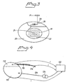
- FIG. 3 shows an example of supplying electric current for infection control from an external source by electromagnetic induction.
- a super thin surface mounted coil 18 is attached to the exterior surface of the stimulator housing 20.
- This coil 18 can be manufactured by e.g. screen printing.
- a polymeric isolation film 22 is provided to electrically isolate the coil 18 from the stimulator housing 20.
- One end 24 of the coil 18 is electrically connected to the housing 20, while the other end is connected to a diode 26 integrated in the epoxy connector head 28.
- the diode 26, in its turn, is connected to a counter electrode 31.
- the coil can be implemented inside the stimulator housing. One end of the coil is then connected to the stimulator housing, whereas the other end of the coil is connected via a diode to an external counter electrode.
- Figure 4 shows an embodiment with the pulse generator housing 10, the connector top 112 and the proximal part 116 of the lead 114 forming one electrode, whereas an external patch electrode 122, intended for application on the patient's skin, is used as counter electrode.
- an external current source 124 is used for delivering treatment current i.
- an electrically conductive needle 126 connected to the current source 124, is inserted through the patient's skin to make contact with a pulse generator housing 10.
- a connecting means can be used for electrolytically connecting an external current source to an implanted electrode.
- the electrolytic connecting means can comprise an additional electrode for external application to the patient's skin, separated from the counter electrode and in electrolytic contact with said first electrode via the body biofluid.
- these electrodes should preferably be positioned such that those parts of the infection control current, which pass through the heart, are minimised.
Landscapes
- Health & Medical Sciences (AREA)
- Life Sciences & Earth Sciences (AREA)
- Animal Behavior & Ethology (AREA)
- Nuclear Medicine, Radiotherapy & Molecular Imaging (AREA)
- Radiology & Medical Imaging (AREA)
- Biomedical Technology (AREA)
- Engineering & Computer Science (AREA)
- General Health & Medical Sciences (AREA)
- Public Health (AREA)
- Veterinary Medicine (AREA)
- Heart & Thoracic Surgery (AREA)
- Vascular Medicine (AREA)
- Cardiology (AREA)
- Biophysics (AREA)
- Electrotherapy Devices (AREA)
Claims (20)
- Implantierbarer Herzstimulator (2) zum Liefern von elektrischen Stimulationsimpulsen zum Herzen (21) eines Patienten, enthaltend wenigstens eine Leitung (6, 14, 114), die mit dem implantierbaren Herzstimulator (2) verbunden ist, dadurch gekennzeichnet, dass die gesamte äußere Fläche des genannten implantierbaren Herzstimulators (2) elektrisch leitend ist und dass ein proximaler Teil (8, 16, 116) der Leitung (6, 14, 114) elektrisch leitend ist, dass sich der genannte proximale Teil bis zu einer Position erstreckt, die nach der Implantation der Leitung zwischen einer Stelle jenseits des Eintritts in das venöse System und des Eintritts in die Vena Cava Superior gelegen ist, dass der genannte implantierbare Herzstimulator (2) und die genannten elektrisch leitenden Oberflächen des genannten proximalen Leitungsteils ausgelegt sind, eine erste Elektrode zu bilden, und dass wenigstens eine zweite Gegenelektrode (19, 31, 122) ausgelegt ist, außerhalb der subkutanen implantierbaren Herzstimulatortasche angeordnet zu werden, in der sich der implantierbare Herzstimulator nach der Implantation befindet, wobei eine Stromquelle vorgesehen ist, um zwischen den genannten Elektroden einen elektrischen Infektionssteuerstrom zuzuführen.
- Implantierbarer Herzstimulator (2) nach Anspruch 1, dadurch gekennzeichnet, dass der genannte Herzstimulator ein Gehäuse mit einer elektrisch leitenden äußeren Fläche und ein Kopfstück oder einen Verbinderaufsatz mit einer elektrisch leitenden Oberfläche enthält, wobei das genannte Gehäuse und der genannte Verbinderaufsatz ausgelegt sind, eine gemeinsame Elektrode zu bilden.
- Implantierbarer Herzstimulator nach Anspruch 1 oder 2, dadurch gekennzeichnet, dass auf der genannten äußeren Fläche des proximalen Teils (16, 116) der genannten Leitung (14, 114) und des genannten Verbinderaufsatzes (4, 12, 28, 112) ein elektrisch leitendes Polymer aufgebracht ist.
- Implantierbarer Herzstimulator nach Anspruch 1, dadurch gekennzeichnet, dass um den genannten proximalen Teil der genannten Leitung (6) eine elektrisch leitende Wicklung (8) angebracht ist.
- Implantierbarer Herzstimulator nach Anspruch 1, dadurch gekennzeichnet, dass die äußeren Flächen des proximalen Teils (16, 116) der genannten Leitung (14, 114) und des genannten Verbinderaufsatzes (4, 12, 28, 112) mittels Ionenimplantationstechnologie oder sogenannter Ionen-Strahl-unterstützter-Ablagerung oder physikalischer Dampfablagerung oder chemischer Aufdampfung oder irgendeinem anderen Zerstäubungsprozess behandelt sind.
- Implantierbarer Herzstimulator nach einem der vorhergehenden Ansprüche, dadurch gekennzeichnet, dass das implantierbare Herzstimulatorgehäuse (2, 10, 20, 110) mit einem der Metalle Platin, Palladium oder Iridium oder irgendeinem anderen Metall mit ähnlichen elektrochemischen Eigenschaften oder einer Legierung dieser Metalle überzogen ist.
- Implantierbarer Herzstimulator nach einem der vorhergehenden Ansprüche, dadurch gekennzeichnet, dass die genannte Gegenelektrode (19) eine implantierbare Elektrode ist.
- Implantierbarer Herzstimulator nach Anspruch 7, dadurch gekennzeichnet, dass die genannte Gegenelektrode ausgebildet ist, auf der genannten Leitung (14) für die Implantation in das Herz (21) des Patienten positioniert zu werden.
- Implantierbarer Herzstimulator nach Anspruch 7 oder 8, dadurch gekennzeichnet, dass die Herzstimulationselektrode die genannte Gegenelektrode bildet.
- Implantierbarer Herzstimulator nach einem der Ansprüche 1 bis 7, dadurch gekennzeichnet, dass die genannte Gegenelektrode aus einer Defibrillationselektrode großer Oberfläche gebildet ist.
- Implantierbarer Herzstimulator nach einem der Ansprüche 1 bis 10, wobei die Stromquelle extern angeordnet ist, dadurch gekennzeichnet, dass Mittel (18) für eine induktive Kopplung der genannten extern angeordneten Stromquelle mit den genannten Elektroden vorgesehen sind.
- Implantierbarer Herzstimulator nach Anspruch 11, dadurch gekennzeichnet, dass das genannte induktive Kopplungsmittel eine dünne induktive Spule (18) enthält, die am Impulsgeneratorgehäuse (20) angebracht und mit den Elektroden elektrisch verbunden ist.
- Implantierbarer Herzstimulator nach Anspruch 12, dadurch gekennzeichnet, dass zwischen die genannte Spule (18) und eine der Elektroden eine Gleichrichtervorrichtung (26) geschaltet ist.
- Implantierbarer Herzstimulator nach einem der Ansprüche 1 bis 6, dadurch gekennzeichnet, dass die genannte Gegenelektrode für eine externe Anwendung auf der Haut des Patienten ausgebildet ist.
- Implantierbarer Herzstimulator nach Anspruch 14, dadurch gekennzeichnet, dass die genannte Gegenelektrode aus einer Patch-Elektrode (122) für ein externes Anbringen auf der Haut des Patienten gebildet ist.
- Implantierbarer Herzstimulator nach Anspruch 14 oder 15, wobei die genannte Stromquelle (124) extern angeordnet ist, dadurch gekennzeichnet, dass ein galvanisches Verbindungsmittel (126) vorgesehen ist, um die genannte Stromquelle (124) über die Haut des Patienten mit den implantierten Elektroden galvanisch zu verbinden.
- Implantierbarer Herzstimulator nach Anspruch 14 oder 15, wobei die genannte Stromquelle extern angeordnet ist, dadurch gekennzeichnet, dass ein elektrolytisches Verbindungsmittel vorgesehen ist, um die genannte Stromquelle über die Haut des Patienten mit der genannten ersten Elektrode elektrolytisch zu verbinden.
- Implantierbarer Herzstimulator nach Anspruch 17, dadurch gekennzeichnet, dass das genannte elektrolytische Verbindungsmittel eine zusätzliche Elektrode für ein externes Anbringen auf der Haut des Patienten enthält, die von der genannten Gegenelektrode getrennt ist und mit der genannten ersten Elektrode in elektrolytischem Kontakt steht, wobei die genannte Stromquelle mit der genannten Gegenelektrode und der genannten zusätzlichen Elektrode verbunden ist.
- Implantierbarer Herzstimulator nach einem der Ansprüche 1 bis 10, dadurch gekennzeichnet, dass die genannte Stromquelle aus einer implantierbaren Herzstimulatorbatterie gebildet ist.
- Herzstimulator enthaltend einen Impulsgenerator zum Liefern elektrischer Stimulationsimpulse zum Herzen (21) eines Patienten über eine Leitung (6, 14, 114), die mit dem genannten Impulsgenerator verbindbar ist, möglicherweise über einen Verbinderaufsatz (4, 12, 28, 112) auf einem Impulsgeneratorgehäuse (2, 10, 20, 110), wobei das genannte Impulsgeneratorgehäuse elektrisch leitend ist, gekennzeichnet durch einen implantierbaren Herzstimulator nach einem der vorhergehenden Ansprüche.
Applications Claiming Priority (3)
| Application Number | Priority Date | Filing Date | Title |
|---|---|---|---|
| SE0100661 | 2001-02-27 | ||
| SE0100661A SE0100661D0 (sv) | 2001-02-27 | 2001-02-27 | Implantable heart stimulator |
| PCT/SE2002/000346 WO2002068043A1 (en) | 2001-02-27 | 2002-02-26 | Implantable heart stimulator |
Publications (2)
| Publication Number | Publication Date |
|---|---|
| EP1365833A1 EP1365833A1 (de) | 2003-12-03 |
| EP1365833B1 true EP1365833B1 (de) | 2005-03-16 |
Family
ID=20283141
Family Applications (1)
| Application Number | Title | Priority Date | Filing Date |
|---|---|---|---|
| EP02701839A Expired - Lifetime EP1365833B1 (de) | 2001-02-27 | 2002-02-26 | Implantierbarer herzstimulator |
Country Status (5)
| Country | Link |
|---|---|
| US (1) | US7242980B2 (de) |
| EP (1) | EP1365833B1 (de) |
| DE (1) | DE60203267T2 (de) |
| SE (1) | SE0100661D0 (de) |
| WO (1) | WO2002068043A1 (de) |
Families Citing this family (6)
| Publication number | Priority date | Publication date | Assignee | Title |
|---|---|---|---|---|
| US7027862B2 (en) * | 2002-07-25 | 2006-04-11 | Medtronic, Inc. | Apparatus and method for transmitting an electrical signal in an implantable medical device |
| US7191009B2 (en) * | 2004-08-09 | 2007-03-13 | Medtronic, Inc. | Means for increasing implantable medical device electrode surface area |
| US20070173712A1 (en) | 2005-12-30 | 2007-07-26 | Medtronic Minimed, Inc. | Method of and system for stabilization of sensors |
| US20070169533A1 (en) | 2005-12-30 | 2007-07-26 | Medtronic Minimed, Inc. | Methods and systems for detecting the hydration of sensors |
| US8594806B2 (en) | 2010-04-30 | 2013-11-26 | Cyberonics, Inc. | Recharging and communication lead for an implantable device |
| US10046165B2 (en) * | 2014-04-21 | 2018-08-14 | University Of South Florida | Magnetic resonant imaging safe stylus |
Family Cites Families (11)
| Publication number | Priority date | Publication date | Assignee | Title |
|---|---|---|---|---|
| US3942535A (en) * | 1973-09-27 | 1976-03-09 | G. D. Searle & Co. | Rechargeable tissue stimulating system |
| US4886505A (en) * | 1985-06-07 | 1989-12-12 | Becton, Dickinson And Company | Antimicrobial surfaces and inhibition of microorganism growth thereby |
| US5713926A (en) | 1990-04-25 | 1998-02-03 | Cardiac Pacemakers, Inc. | Implantable intravenous cardiac stimulation system with pulse generator housing serving as optional additional electrode |
| AU1672492A (en) | 1991-05-03 | 1992-12-21 | University Technologies International Inc. | Biofilm reduction method |
| US6004438A (en) * | 1991-12-31 | 1999-12-21 | 3M Innovative Properties Company | Biofilm reduction sterilizer |
| AU4939293A (en) | 1992-09-11 | 1994-04-12 | Instantel Inc. | Intrusion detection system |
| US5409467A (en) * | 1992-10-02 | 1995-04-25 | Board Of Regents, The University Of Texas System | Antimicrobial catheter |
| US5814076A (en) * | 1996-02-09 | 1998-09-29 | Cardiac Control Systems, Inc. | Apparatus for improved cardiac pacing and sensing using extracardiac indifferent electrode configurations |
| US6282444B1 (en) * | 1999-08-31 | 2001-08-28 | Pacesetter, Inc. | Implantable device with electrical infection control |
| US6258249B1 (en) * | 1999-11-10 | 2001-07-10 | Sulzer Carbomedics Inc. | Sterilization of surgical sites |
| US6493586B1 (en) * | 2000-08-30 | 2002-12-10 | Cardiac Pacemakers, Inc. | Site reversion in cardiac rhythm management |
-
2001
- 2001-02-27 SE SE0100661A patent/SE0100661D0/xx unknown
-
2002
- 2002-02-26 EP EP02701839A patent/EP1365833B1/de not_active Expired - Lifetime
- 2002-02-26 WO PCT/SE2002/000346 patent/WO2002068043A1/en not_active Ceased
- 2002-02-26 US US10/468,589 patent/US7242980B2/en not_active Expired - Fee Related
- 2002-02-26 DE DE60203267T patent/DE60203267T2/de not_active Expired - Lifetime
Also Published As
| Publication number | Publication date |
|---|---|
| SE0100661D0 (sv) | 2001-02-27 |
| EP1365833A1 (de) | 2003-12-03 |
| US20040093036A1 (en) | 2004-05-13 |
| US7242980B2 (en) | 2007-07-10 |
| WO2002068043A1 (en) | 2002-09-06 |
| DE60203267T2 (de) | 2006-02-09 |
| DE60203267D1 (de) | 2005-04-21 |
Similar Documents
| Publication | Publication Date | Title |
|---|---|---|
| EP1365838B1 (de) | Implantierbare vorrichtung | |
| US6282444B1 (en) | Implantable device with electrical infection control | |
| US5632770A (en) | Implantable defibrillation system with lead having improved porous surface coating | |
| US5871529A (en) | Electrode for high impedance heart stimulation | |
| AU2006315285B2 (en) | Implantable stimulator configured to be implanted within a patient in a pre-determined orientation | |
| EP0670743B1 (de) | Koronarsinusleitung die die erfassung von vorhofsignalen ermöglicht | |
| US20090088827A1 (en) | Lead assembly providing sensing or stimulation of spaced-apart myocardial contact areas | |
| US20020042643A1 (en) | Ring electrode with porous member | |
| US5562715A (en) | Cardiac pulse generator | |
| JP2005515852A (ja) | 耐mri電極システムのための遮蔽被膜の方法及び装置 | |
| WO2003002194A2 (en) | Low impedance implantable extension for a neurological electricalstimulator | |
| US5713945A (en) | Implantable lead modified to reduce tissue ingrowth | |
| US20090204194A1 (en) | Medical system including a novel bipolar pacing pair | |
| WO2007117899A2 (en) | Implantable medical electrode | |
| US20050038476A1 (en) | Coating/covering materials for the enhancement of defibrillation thresholds of implantable defibrillators/leads | |
| WO2008013908A1 (en) | Lead comprising electrode-shared drug region | |
| MXPA04010825A (es) | Desfibrilador automatico implantable con electrodos subcutaneos. | |
| US6490489B2 (en) | Implantable cardiac single pass coronary sinus lead for providing pacing and defibrillation and method of manufacture | |
| EP1365833B1 (de) | Implantierbarer herzstimulator | |
| US20100324617A1 (en) | Adapter for electrostimulation lead and method for reducing extracardiac stimulation | |
| US6321122B1 (en) | Single pass defibrillation/pacing lead with passively attached electrode for pacing and sensing | |
| US7058454B1 (en) | Stimulation/sensing electrodes for use with implantable cardiac leads in coronary vein locations | |
| EP1365837B1 (de) | Implantierbarer herzstimulator |
Legal Events
| Date | Code | Title | Description |
|---|---|---|---|
| PUAI | Public reference made under article 153(3) epc to a published international application that has entered the european phase |
Free format text: ORIGINAL CODE: 0009012 |
|
| 17P | Request for examination filed |
Effective date: 20030929 |
|
| AK | Designated contracting states |
Kind code of ref document: A1 Designated state(s): AT BE CH CY DE DK ES FI FR GB GR IE IT LI LU MC NL PT SE TR |
|
| RIN1 | Information on inventor provided before grant (corrected) |
Inventor name: MICSKI, EVA Inventor name: OBEL, MARTIN Inventor name: ECKERDAL, JOHAN |
|
| GRAP | Despatch of communication of intention to grant a patent |
Free format text: ORIGINAL CODE: EPIDOSNIGR1 |
|
| GRAS | Grant fee paid |
Free format text: ORIGINAL CODE: EPIDOSNIGR3 |
|
| GRAA | (expected) grant |
Free format text: ORIGINAL CODE: 0009210 |
|
| AK | Designated contracting states |
Kind code of ref document: B1 Designated state(s): CH DE FR IE IT LI |
|
| REG | Reference to a national code |
Ref country code: CH Ref legal event code: EP |
|
| REG | Reference to a national code |
Ref country code: CH Ref legal event code: NV Representative=s name: E. BLUM & CO. PATENTANWAELTE |
|
| REG | Reference to a national code |
Ref country code: IE Ref legal event code: FG4D |
|
| REF | Corresponds to: |
Ref document number: 60203267 Country of ref document: DE Date of ref document: 20050421 Kind code of ref document: P |
|
| PLBE | No opposition filed within time limit |
Free format text: ORIGINAL CODE: 0009261 |
|
| STAA | Information on the status of an ep patent application or granted ep patent |
Free format text: STATUS: NO OPPOSITION FILED WITHIN TIME LIMIT |
|
| ET | Fr: translation filed | ||
| 26N | No opposition filed |
Effective date: 20051219 |
|
| REG | Reference to a national code |
Ref country code: CH Ref legal event code: PFA Owner name: ST. JUDE MEDICAL AB Free format text: ST. JUDE MEDICAL AB# #175 84 JAERFAELLA (SE) -TRANSFER TO- ST. JUDE MEDICAL AB# #175 84 JAERFAELLA (SE) |
|
| PGFP | Annual fee paid to national office [announced via postgrant information from national office to epo] |
Ref country code: IE Payment date: 20080214 Year of fee payment: 7 |
|
| REG | Reference to a national code |
Ref country code: IE Ref legal event code: MM4A |
|
| PG25 | Lapsed in a contracting state [announced via postgrant information from national office to epo] |
Ref country code: IE Free format text: LAPSE BECAUSE OF NON-PAYMENT OF DUE FEES Effective date: 20090226 |
|
| PGFP | Annual fee paid to national office [announced via postgrant information from national office to epo] |
Ref country code: FR Payment date: 20120316 Year of fee payment: 11 |
|
| PGFP | Annual fee paid to national office [announced via postgrant information from national office to epo] |
Ref country code: IT Payment date: 20120222 Year of fee payment: 11 |
|
| PGFP | Annual fee paid to national office [announced via postgrant information from national office to epo] |
Ref country code: CH Payment date: 20130325 Year of fee payment: 12 |
|
| REG | Reference to a national code |
Ref country code: FR Ref legal event code: ST Effective date: 20131031 |
|
| PG25 | Lapsed in a contracting state [announced via postgrant information from national office to epo] |
Ref country code: IT Free format text: LAPSE BECAUSE OF NON-PAYMENT OF DUE FEES Effective date: 20130226 |
|
| PG25 | Lapsed in a contracting state [announced via postgrant information from national office to epo] |
Ref country code: FR Free format text: LAPSE BECAUSE OF NON-PAYMENT OF DUE FEES Effective date: 20130228 |
|
| REG | Reference to a national code |
Ref country code: CH Ref legal event code: PL |
|
| PG25 | Lapsed in a contracting state [announced via postgrant information from national office to epo] |
Ref country code: LI Free format text: LAPSE BECAUSE OF NON-PAYMENT OF DUE FEES Effective date: 20140228 Ref country code: CH Free format text: LAPSE BECAUSE OF NON-PAYMENT OF DUE FEES Effective date: 20140228 |
|
| PGFP | Annual fee paid to national office [announced via postgrant information from national office to epo] |
Ref country code: DE Payment date: 20160226 Year of fee payment: 15 |
|
| REG | Reference to a national code |
Ref country code: DE Ref legal event code: R119 Ref document number: 60203267 Country of ref document: DE |
|
| PG25 | Lapsed in a contracting state [announced via postgrant information from national office to epo] |
Ref country code: DE Free format text: LAPSE BECAUSE OF NON-PAYMENT OF DUE FEES Effective date: 20170901 |