EP1366479B1 - Vorrichtung zur detektion der lauffläche und fahrzeug mit solch einer einrichtung - Google Patents
Vorrichtung zur detektion der lauffläche und fahrzeug mit solch einer einrichtung Download PDFInfo
- Publication number
- EP1366479B1 EP1366479B1 EP02718252A EP02718252A EP1366479B1 EP 1366479 B1 EP1366479 B1 EP 1366479B1 EP 02718252 A EP02718252 A EP 02718252A EP 02718252 A EP02718252 A EP 02718252A EP 1366479 B1 EP1366479 B1 EP 1366479B1
- Authority
- EP
- European Patent Office
- Prior art keywords
- sensors
- ground
- vehicle
- distance
- substantially equal
- Prior art date
- Legal status (The legal status is an assumption and is not a legal conclusion. Google has not performed a legal analysis and makes no representation as to the accuracy of the status listed.)
- Expired - Lifetime
Links
- 238000012986 modification Methods 0.000 claims abstract description 4
- 230000004048 modification Effects 0.000 claims abstract description 4
- 238000001514 detection method Methods 0.000 claims description 38
- 238000005096 rolling process Methods 0.000 description 5
- 230000004913 activation Effects 0.000 description 3
- 230000002159 abnormal effect Effects 0.000 description 1
- 230000005540 biological transmission Effects 0.000 description 1
- 230000001143 conditioned effect Effects 0.000 description 1
- 238000010586 diagram Methods 0.000 description 1
- 238000005259 measurement Methods 0.000 description 1
- 238000012544 monitoring process Methods 0.000 description 1
- 230000011664 signaling Effects 0.000 description 1
- 239000002689 soil Substances 0.000 description 1
- 238000002604 ultrasonography Methods 0.000 description 1
Images

Classifications
-
- B—PERFORMING OPERATIONS; TRANSPORTING
- B60—VEHICLES IN GENERAL
- B60Q—ARRANGEMENT OF SIGNALLING OR LIGHTING DEVICES, THE MOUNTING OR SUPPORTING THEREOF OR CIRCUITS THEREFOR, FOR VEHICLES IN GENERAL
- B60Q1/00—Arrangement of optical signalling or lighting devices, the mounting or supporting thereof or circuits therefor
- B60Q1/26—Arrangement of optical signalling or lighting devices, the mounting or supporting thereof or circuits therefor the devices being primarily intended to indicate the vehicle, or parts thereof, or to give signals, to other traffic
- B60Q1/34—Arrangement of optical signalling or lighting devices, the mounting or supporting thereof or circuits therefor the devices being primarily intended to indicate the vehicle, or parts thereof, or to give signals, to other traffic for indicating change of drive direction
- B60Q1/346—Arrangement of optical signalling or lighting devices, the mounting or supporting thereof or circuits therefor the devices being primarily intended to indicate the vehicle, or parts thereof, or to give signals, to other traffic for indicating change of drive direction with automatic actuation
-
- G—PHYSICS
- G08—SIGNALLING
- G08G—TRAFFIC CONTROL SYSTEMS
- G08G1/00—Traffic control systems for road vehicles
- G08G1/09—Arrangements for giving variable traffic instructions
- G08G1/0962—Arrangements for giving variable traffic instructions having an indicator mounted inside the vehicle, e.g. giving voice messages
Landscapes
- Engineering & Computer Science (AREA)
- Mechanical Engineering (AREA)
- Physics & Mathematics (AREA)
- General Physics & Mathematics (AREA)
- Traffic Control Systems (AREA)
- Length Measuring Devices With Unspecified Measuring Means (AREA)
- Length Measuring Devices By Optical Means (AREA)
- Automobile Manufacture Line, Endless Track Vehicle, Trailer (AREA)
- Forklifts And Lifting Vehicles (AREA)
Claims (16)
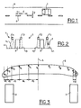
- Vorrichtung zum Erfassen einer Fahrbahnoberfläche für ein Fahrzeug, mit mehreren Sensoren (c1 bis cn), die auf die Fahrbahnoberfläche (4) gerichtet werden, um Veränderungen an dieser festzustellen, und mit einer Einrichtung (2) zum Verarbeiten der von den Sensoren gewonnenen Daten, dadurch gekennzeichnet, dass mindestens ein Teil der Sensoren derart zueinander angeordnet ist, dass die Querabstände (d1 bis d10) zwischen zwei benachbarten Beobachtungspunkten auf dem Boden (v1 bis v11) der Sensoren (cn) zur Längsachse (5) hin in einer Richtung zunehmen, die im Wesentlichen senkrecht zur Achse (5) verläuft.
- Erfassungsvorrichtung nach Anspruch 1, dadurch gekennzeichnet, dass sie mindestens fünf Sensoren (c1 bis c5) umfasst.
- Erfassungsvorrichtung nach Anspruch 1 oder 2, dadurch gekennzeichnet, dass die Sensoren (c1 bis cn) auf beiden Seiten einer Längsmittelachse (5) angeordnet sind und dass die Querabstände (d1 bis d10) zwischen den Beobachtungspunkten auf dem Boden (vn) der Sensoren im Wesentlichen symmetrisch gegenüber der Achse (5) sind.
- Erfassungsvorrichtung nach einem der Ansprüche 1 bis 3, dadurch gekennzeichnet, dass der Querabstand (dn) in Zentimeter zwischen zwei benachbarten Beobachtungspunkten auf dem Boden (vn, vn+1) durch die Formel dn = k.Rn gegeben ist, bei der n die laufende Nummer des Beobachtungspunktes auf dem Boden (vn) zur Längsachse (5) hin ist, R ein erster konstanter multiplikativer Koeffizient, der im Wesentlichen 1,2 entspricht, und k ein zweiter konstanter Koeffizient, der im Wesentlichen 10 entspricht.
- Vorrichtung nach einem der Ansprüche 1 bis 3, dadurch gekennzeichnet, dass der Abstand d 1 zwischen dem ersten Beobachtungspunkt v1 und dem zweiten Beobachtungspunkt v2 auf dem Boden im Wesentlichen 12 Zentimeter entspricht, der Abstand d2 zwischen dem zweiten Beobachtungspunkt v2 und dem dritten Beobachtungspunkt auf dem Boden v3 im Wesentlichen 14,4, Zentimeter, der Abstand d3 zwischen dem dritten Beobachtungspunkt v3 und dem vierten Beobachtungspunkt v4 auf dem Boden im Wesentlichen 17,3 Zentimeter, der Abstand d4 zwischen dem vierten Beobachtungspunkt v4 und dem fünften Beobachtungspunkt v5 auf dem Boden im Wesentlichen 20,7 Zentimeter und der Abstand d5 zwischen dem fünften Beobachtungspunkt v5 und dem sechsten Beobachtungspunkt v6 auf dem Boden im Wesentlichen 25 Zentimeter.
- Erfassungsvorrichtung nach einem der Ansprüche 1 bis 3, dadurch gekennzeichnet, dass der Querabstand (dn) in Zentimeter zwischen zwei benachbarten Beobachtungspunkten auf dem Boden (vn, vn+1) der Sensoren durch die Formel
- Fahrzeug mit einer Erfassungsvorrichtung nach einem der vorhergehenden Ansprüche.
- Fahrzeug nach Anspruch 7, dadurch gekennzeichnet, dass die Sensoren (c1 bis c11) auf beiden Seiten der Längsmittelachse (5) des Fahrzeugs angeordnet sind und dass die Querabstände (d1 bis d10) zwischen den Beobachtungspunkten auf dem Boden (v1 bis v11) der Sensoren im Wesentlichen symmetrisch gegenüber der Achse (5) sind.
- Fahrzeug nach Anspruch 7 oder 8, dadurch gekennzeichnet, dass der Querabstand (dn) in Zentimeter zwischen zwei benachbarten Beobachtungspunkten auf dem Boden (vn, vn+ 1) der Sensoren durch die Formel dn = k.Rn gegeben ist, wobei n die laufende Nummer des Beobachtungspunktes auf dem Boden (vn) zur Längsachse (5) hin ist, R ein erster konstanter multiplikativer Koeffizient, der im Wesentlichen 1,2 entspricht, und k ein zweiter konstanter Koeffizient, der im Wesentlichen 10 entspricht.
- Fahrzeug nach Anspruch 7 oder 8, dadurch gekennzeichnet, dass der Querabstand (dn) in Zentimeter zwischen zwei benachbarten Beobachtungspunkten auf dem Boden (vn, vn+1) der Sensoren durch die Formel
- Fahrzeug nach einem der Ansprüche 7 bis 10, dadurch gekennzeichnet, dass es elf Sensoren (c1 bis c11) umfasst.
- Fahrzeug nach Anspruch 11, dadurch gekennzeichnet, dass der Abstand d1 zwischen dem ersten Beobachtungspunkt v1 und dem zweiten Beobachtungspunkt v2 auf dem Boden im Wesentlichen 12 Zentimeter entspricht, der Abstand d2 zwischen dem zweiten Beobachtungspunkt v2 und dem dritten Beobachtungspunkt v3 auf dem Boden im Wesentlichen 14,4, Zentimeter, der Abstand d3 zwischen dem dritten Beobachtungspunkt v3 und dem vierten Beobachtungspunkt v4 auf dem Boden im Wesentlichen 17,3 Zentimeter, der Abstand d4 zwischen dem vierten Beobachtungspunkt v4 und dem fünften Beobachtungspunkt v5 auf dem Boden im Wesentlichen 20,7 Zentimeter und der Abstand d5 zwischen dem fünften Beobachtungspunkt v5 und dem sechsten Beobachtungspunkt v6 auf dem Boden im Wesentlichen 25 Zentimeter.
- Fahrzeug nach einem der Ansprüche 7 bis 12, dadurch gekennzeichnet, dass mindestens ein Teil der Sensoren (c1 bis c11) seitlich zur Außenseite des Fahrzeugs gerichtet ist.
- Fahrzeug nach einem der Ansprüche 7 bis 13, dadurch gekennzeichnet, dass mindestens ein Teil der Sensoren (c 1 bis c11) gegenüber der Vertikalen um einen Winkel geneigt ist, der im Wesentlichen gleich oder größer ist als ihr Halbwinkel (A) des Sichtkegels (7).
- Fahrzeug nach einem der Ansprüche 7 bis 14, dadurch gekennzeichnet, dass mindestens ein Teil der Sensoren (c 1 bis c11) gegenüber der Vertikalen um einen Winkel zwischen ungefähr 5 und 45 Grad geneigt ist.
- Fahrzeug nach einem der Ansprüche 7 bis 15, dadurch gekennzeichnet, dass mindestens ein Teil der Sensoren (c1 bis c11) im vorderen Schild (8) des Fahrzeugs angeordnet ist.
Applications Claiming Priority (3)
| Application Number | Priority Date | Filing Date | Title |
|---|---|---|---|
| FR0103163 | 2001-03-08 | ||
| FR0103163A FR2821963B1 (fr) | 2001-03-08 | 2001-03-08 | Dispositif de detection d'une surface de roulement et vehicule utilisant un tel dispositif |
| PCT/FR2002/000829 WO2002077948A1 (fr) | 2001-03-08 | 2002-03-07 | Dispositif de detection d'une surface de roulement pour vehicule et vehicule utilisant un tel dispositif |
Publications (2)
| Publication Number | Publication Date |
|---|---|
| EP1366479A1 EP1366479A1 (de) | 2003-12-03 |
| EP1366479B1 true EP1366479B1 (de) | 2005-11-09 |
Family
ID=8860887
Family Applications (1)
| Application Number | Title | Priority Date | Filing Date |
|---|---|---|---|
| EP02718252A Expired - Lifetime EP1366479B1 (de) | 2001-03-08 | 2002-03-07 | Vorrichtung zur detektion der lauffläche und fahrzeug mit solch einer einrichtung |
Country Status (7)
| Country | Link |
|---|---|
| US (1) | US7012509B2 (de) |
| EP (1) | EP1366479B1 (de) |
| AT (1) | ATE309593T1 (de) |
| DE (1) | DE60207213T2 (de) |
| ES (1) | ES2248539T3 (de) |
| FR (1) | FR2821963B1 (de) |
| WO (1) | WO2002077948A1 (de) |
Cited By (1)
| Publication number | Priority date | Publication date | Assignee | Title |
|---|---|---|---|---|
| DE202007000441U1 (de) * | 2007-01-05 | 2008-05-15 | Brose Fahrzeugteile Gmbh & Co. Kommanditgesellschaft, Coburg | Kraftfahrzeugsitz mit Vibrator |
Families Citing this family (3)
| Publication number | Priority date | Publication date | Assignee | Title |
|---|---|---|---|---|
| FR2821962B1 (fr) | 2001-03-08 | 2003-04-25 | Peugeot Citroen Automobiles Sa | Dispositif de detection d'une surface de roulement et vehicule utilisant un tel dispositif |
| EP1387184A1 (de) * | 2002-07-25 | 2004-02-04 | EM Microelectronic-Marin SA | Spurabdriftdetektionsgerät |
| DE102006050214A1 (de) * | 2005-11-04 | 2007-05-24 | Continental Teves Ag & Co. Ohg | Verfahren zum Unterstützen eines Fahrers beim Fahren mit einem Fahrzeug |
Family Cites Families (16)
| Publication number | Priority date | Publication date | Assignee | Title |
|---|---|---|---|---|
| US3708668A (en) | 1971-06-01 | 1973-01-02 | J Tilley | Vehicle optical guidance system |
| US4348652A (en) * | 1980-09-29 | 1982-09-07 | Robert R. Barnes | Driver alert system |
| DE3071811D1 (en) * | 1980-10-09 | 1986-12-04 | Claude Fricot | Apparatus for indicating trajectory change |
| US4401181A (en) | 1981-03-12 | 1983-08-30 | Schwarz Alfred V | Road vehicle control system |
| SE461260B (sv) * | 1988-10-24 | 1990-01-29 | Goeran Persson | Foer motorfordon avsedd varningsanordning foer avgivande av varningssignaler |
| IT1238543B (it) * | 1990-04-05 | 1993-08-18 | Nevio Nati | Dispositivo elettronico di sicurezza per automezzi perfezionato. |
| DE19507957C1 (de) * | 1995-03-07 | 1996-09-12 | Daimler Benz Ag | Fahrzeug mit optischer Abtasteinrichtung für einen seitlichen Fahrbahnbereich |
| JPH0939601A (ja) | 1995-08-04 | 1997-02-10 | Mitsubishi Motors Corp | 居眠り運転警報装置 |
| US5568137A (en) * | 1995-09-26 | 1996-10-22 | Liu; Jian S. | Vehicle lane guide and alerting device |
| ES2140138T3 (es) * | 1995-11-06 | 2000-02-16 | Michel Cuvelier | Dispositivo de vigilancia de carreteras. |
| GB2317009A (en) | 1996-09-07 | 1998-03-11 | John Joseph Green | driver sleep warning system |
| FR2759647B1 (fr) * | 1997-02-17 | 1999-05-07 | Dominique Pecquet | Appareil destine a prevenir par un signal sonore le conducteur automobile fatigue ou distrait, d'un changement involontaire de trajectoire de son vehicule |
| US6194486B1 (en) | 1997-05-28 | 2001-02-27 | Trw Inc. | Enhanced paint for microwave/millimeter wave radiometric detection applications and method of road marker detection |
| EP0960775A1 (de) * | 1998-05-27 | 1999-12-01 | Settimo Martinello | Einrichtung zum Erkennen und Melden dass ein fahrendes Fahrzeug zur Fahrbahn ausfahren wird |
| US6894606B2 (en) | 2000-11-22 | 2005-05-17 | Fred Forbes | Vehicular black box monitoring system |
| US6498570B2 (en) | 2001-05-24 | 2002-12-24 | Phillip N. Ross | Optical highway line detector |
-
2001
- 2001-03-08 FR FR0103163A patent/FR2821963B1/fr not_active Expired - Fee Related
-
2002
- 2002-03-07 WO PCT/FR2002/000829 patent/WO2002077948A1/fr not_active Ceased
- 2002-03-07 ES ES02718252T patent/ES2248539T3/es not_active Expired - Lifetime
- 2002-03-07 US US10/474,484 patent/US7012509B2/en not_active Expired - Fee Related
- 2002-03-07 DE DE60207213T patent/DE60207213T2/de not_active Expired - Lifetime
- 2002-03-07 AT AT02718252T patent/ATE309593T1/de not_active IP Right Cessation
- 2002-03-07 EP EP02718252A patent/EP1366479B1/de not_active Expired - Lifetime
Cited By (1)
| Publication number | Priority date | Publication date | Assignee | Title |
|---|---|---|---|---|
| DE202007000441U1 (de) * | 2007-01-05 | 2008-05-15 | Brose Fahrzeugteile Gmbh & Co. Kommanditgesellschaft, Coburg | Kraftfahrzeugsitz mit Vibrator |
Also Published As
| Publication number | Publication date |
|---|---|
| WO2002077948A1 (fr) | 2002-10-03 |
| FR2821963A1 (fr) | 2002-09-13 |
| DE60207213D1 (de) | 2005-12-15 |
| FR2821963B1 (fr) | 2003-04-25 |
| EP1366479A1 (de) | 2003-12-03 |
| DE60207213T2 (de) | 2006-07-27 |
| US7012509B2 (en) | 2006-03-14 |
| ATE309593T1 (de) | 2005-11-15 |
| US20050039960A1 (en) | 2005-02-24 |
| ES2248539T3 (es) | 2006-03-16 |
Similar Documents
| Publication | Publication Date | Title |
|---|---|---|
| EP0658775B1 (de) | Kollisionsschutzeinrichtung für Kraftfahrzeuge | |
| FR2899332A1 (fr) | Dispositif de mesure de champ de visibilite pour vehicule et systeme d'assistance a la conduite pour vehicule | |
| CA2106115A1 (fr) | Systeme de calcul d'au moins un parametre de controle de trafic de vehicules | |
| WO2020008062A1 (fr) | Adaptation d'une fonction de feu de route d'un véhicule automobile | |
| FR2815311A1 (fr) | Procede d'indication du changement de direction d'un vehicule automobile et dispositif de mise en oeuvre du procede | |
| FR3035364A1 (fr) | Procede de gestion d'un systeme de reconnaissance d'objet pour des vehicules inclinables et systeme de mise en oeuvre du procede | |
| EP1724153B1 (de) | Vorrichtung zur Beleuchtung oder Signalisierung für Kraftfahrzeug | |
| EP1431918A1 (de) | Verfahren und Vorrichtung zur Erkennung von Fahrbahnkurven | |
| EP1275096B1 (de) | Vorrichtung zur erfassung der strassenoberfläche und fahrzeug mit einer derartigen vorrichtung | |
| EP2282294B1 (de) | Verfahren zur Definition eines Suchfensters | |
| FR2905765A1 (fr) | Dispositif et procede d'estimation des dimensions d'une place de parking, vehicule automobile comportant un tel dispositif. | |
| FR2995269A1 (fr) | Dispositif holographique de signalisation pour vehicule | |
| WO2002077948A1 (fr) | Dispositif de detection d'une surface de roulement pour vehicule et vehicule utilisant un tel dispositif | |
| EP3488380B1 (de) | Verfahren zum bestimmen einer blendungshöhe für einen kraftfahrzeugführer | |
| FR2987325A1 (fr) | Procede de detection d'obstacles mobiles dans l'angle mort d'un vehicule automobile | |
| FR3047589A1 (fr) | Procede et dispositif d'estimation de la position laterale d'un vehicule dans une voie de circulation | |
| FR2899369A1 (fr) | Procede et systeme de detection de la circulation d'un vehicule a contresens au moyen d'un detecteur a formation d'images | |
| FR3045546A1 (fr) | Procede d’emission d’une signaletique visuelle sur volant durant une phase de conduite entierement automatisee. | |
| FR3085746A1 (fr) | Procede de detection de faux positifs d’un dispositif de traitement d’image d’une camera | |
| EP4136475A1 (de) | Verfahren zur erkennung einer verkehrsstausituation in einem kraftfahrzeug | |
| FR2938485A1 (fr) | Detection de "2 roue" a l'arriere ou dans l'angle mort d'un vehicule | |
| FR2795852A1 (fr) | Dispositif embarque d'assistance au controle des deplacements d'un vehicule automobile en vue d'une manoeuvre de changement de voie | |
| EP3837568B1 (de) | Verfahren zur bestimmung eines konfidenzindexes im zusammenhang mit einem objekt, das von einem sensor in der umgebung eines kraftfahrzeugs erkannt wurde | |
| WO2020025260A1 (fr) | Procédé de détermination d'un type d'emplacement de stationnement | |
| FR3104235A1 (fr) | Procédé et système de commande d’un feu de croisement adaptatif aux virages configuré pour adapter l’angle d’activation dudit feu |
Legal Events
| Date | Code | Title | Description |
|---|---|---|---|
| PUAI | Public reference made under article 153(3) epc to a published international application that has entered the european phase |
Free format text: ORIGINAL CODE: 0009012 |
|
| 17P | Request for examination filed |
Effective date: 20030919 |
|
| AK | Designated contracting states |
Kind code of ref document: A1 Designated state(s): AT BE CH CY DE DK ES FI FR GB GR IE IT LI LU MC NL PT SE TR |
|
| AX | Request for extension of the european patent |
Extension state: AL LT LV MK RO SI |
|
| TPAC | Observations filed by third parties |
Free format text: ORIGINAL CODE: EPIDOSNTIPA |
|
| GRAP | Despatch of communication of intention to grant a patent |
Free format text: ORIGINAL CODE: EPIDOSNIGR1 |
|
| RIC1 | Information provided on ipc code assigned before grant |
Ipc: 7G 08G 1/0962 A |
|
| GRAS | Grant fee paid |
Free format text: ORIGINAL CODE: EPIDOSNIGR3 |
|
| GRAA | (expected) grant |
Free format text: ORIGINAL CODE: 0009210 |
|
| AK | Designated contracting states |
Kind code of ref document: B1 Designated state(s): AT BE CH CY DE DK ES FI FR GB GR IE IT LI LU MC NL PT SE TR |
|
| GBT | Gb: translation of ep patent filed (gb section 77(6)(a)/1977) | ||
| PG25 | Lapsed in a contracting state [announced via postgrant information from national office to epo] |
Ref country code: AT Free format text: LAPSE BECAUSE OF FAILURE TO SUBMIT A TRANSLATION OF THE DESCRIPTION OR TO PAY THE FEE WITHIN THE PRESCRIBED TIME-LIMIT Effective date: 20051109 Ref country code: FI Free format text: LAPSE BECAUSE OF FAILURE TO SUBMIT A TRANSLATION OF THE DESCRIPTION OR TO PAY THE FEE WITHIN THE PRESCRIBED TIME-LIMIT Effective date: 20051109 Ref country code: IE Free format text: LAPSE BECAUSE OF FAILURE TO SUBMIT A TRANSLATION OF THE DESCRIPTION OR TO PAY THE FEE WITHIN THE PRESCRIBED TIME-LIMIT Effective date: 20051109 Ref country code: NL Free format text: LAPSE BECAUSE OF FAILURE TO SUBMIT A TRANSLATION OF THE DESCRIPTION OR TO PAY THE FEE WITHIN THE PRESCRIBED TIME-LIMIT Effective date: 20051109 |
|
| REG | Reference to a national code |
Ref country code: GB Ref legal event code: FG4D Free format text: NOT ENGLISH |
|
| REG | Reference to a national code |
Ref country code: CH Ref legal event code: EP |
|
| GBT | Gb: translation of ep patent filed (gb section 77(6)(a)/1977) |
Effective date: 20051109 |
|
| REG | Reference to a national code |
Ref country code: IE Ref legal event code: FG4D Free format text: LANGUAGE OF EP DOCUMENT: FRENCH |
|
| REF | Corresponds to: |
Ref document number: 60207213 Country of ref document: DE Date of ref document: 20051215 Kind code of ref document: P |
|
| PG25 | Lapsed in a contracting state [announced via postgrant information from national office to epo] |
Ref country code: SE Free format text: LAPSE BECAUSE OF FAILURE TO SUBMIT A TRANSLATION OF THE DESCRIPTION OR TO PAY THE FEE WITHIN THE PRESCRIBED TIME-LIMIT Effective date: 20060209 Ref country code: GR Free format text: LAPSE BECAUSE OF FAILURE TO SUBMIT A TRANSLATION OF THE DESCRIPTION OR TO PAY THE FEE WITHIN THE PRESCRIBED TIME-LIMIT Effective date: 20060209 Ref country code: DK Free format text: LAPSE BECAUSE OF FAILURE TO SUBMIT A TRANSLATION OF THE DESCRIPTION OR TO PAY THE FEE WITHIN THE PRESCRIBED TIME-LIMIT Effective date: 20060209 |
|
| REG | Reference to a national code |
Ref country code: ES Ref legal event code: FG2A Ref document number: 2248539 Country of ref document: ES Kind code of ref document: T3 |
|
| PG25 | Lapsed in a contracting state [announced via postgrant information from national office to epo] |
Ref country code: LU Free format text: LAPSE BECAUSE OF NON-PAYMENT OF DUE FEES Effective date: 20060331 Ref country code: LI Free format text: LAPSE BECAUSE OF NON-PAYMENT OF DUE FEES Effective date: 20060331 Ref country code: BE Free format text: LAPSE BECAUSE OF NON-PAYMENT OF DUE FEES Effective date: 20060331 Ref country code: MC Free format text: LAPSE BECAUSE OF NON-PAYMENT OF DUE FEES Effective date: 20060331 Ref country code: CH Free format text: LAPSE BECAUSE OF NON-PAYMENT OF DUE FEES Effective date: 20060331 |
|
| PG25 | Lapsed in a contracting state [announced via postgrant information from national office to epo] |
Ref country code: PT Free format text: LAPSE BECAUSE OF FAILURE TO SUBMIT A TRANSLATION OF THE DESCRIPTION OR TO PAY THE FEE WITHIN THE PRESCRIBED TIME-LIMIT Effective date: 20060410 |
|
| NLV1 | Nl: lapsed or annulled due to failure to fulfill the requirements of art. 29p and 29m of the patents act | ||
| REG | Reference to a national code |
Ref country code: IE Ref legal event code: FD4D |
|
| PLBE | No opposition filed within time limit |
Free format text: ORIGINAL CODE: 0009261 |
|
| STAA | Information on the status of an ep patent application or granted ep patent |
Free format text: STATUS: NO OPPOSITION FILED WITHIN TIME LIMIT |
|
| 26N | No opposition filed |
Effective date: 20060810 |
|
| REG | Reference to a national code |
Ref country code: CH Ref legal event code: PL |
|
| REG | Reference to a national code |
Ref country code: GB Ref legal event code: 746 Effective date: 20070117 |
|
| BERE | Be: lapsed |
Owner name: PEUGEOT CITROEN AUTOMOBILES Effective date: 20060331 |
|
| PG25 | Lapsed in a contracting state [announced via postgrant information from national office to epo] |
Ref country code: TR Free format text: LAPSE BECAUSE OF FAILURE TO SUBMIT A TRANSLATION OF THE DESCRIPTION OR TO PAY THE FEE WITHIN THE PRESCRIBED TIME-LIMIT Effective date: 20051109 |
|
| PG25 | Lapsed in a contracting state [announced via postgrant information from national office to epo] |
Ref country code: CY Free format text: LAPSE BECAUSE OF FAILURE TO SUBMIT A TRANSLATION OF THE DESCRIPTION OR TO PAY THE FEE WITHIN THE PRESCRIBED TIME-LIMIT Effective date: 20051109 |
|
| REG | Reference to a national code |
Ref country code: ES Ref legal event code: GC2A Effective date: 20110406 |
|
| REG | Reference to a national code |
Ref country code: FR Ref legal event code: PLFP Year of fee payment: 15 |
|
| REG | Reference to a national code |
Ref country code: FR Ref legal event code: PLFP Year of fee payment: 16 |
|
| REG | Reference to a national code |
Ref country code: FR Ref legal event code: PLFP Year of fee payment: 17 |
|
| REG | Reference to a national code |
Ref country code: FR Ref legal event code: CA Effective date: 20180312 Ref country code: FR Ref legal event code: CD Owner name: PEUGEOT CITROEN AUTOMOBILES SA, FR Effective date: 20180312 |
|
| PGFP | Annual fee paid to national office [announced via postgrant information from national office to epo] |
Ref country code: ES Payment date: 20190401 Year of fee payment: 18 |
|
| PGFP | Annual fee paid to national office [announced via postgrant information from national office to epo] |
Ref country code: FR Payment date: 20210218 Year of fee payment: 20 |
|
| PGFP | Annual fee paid to national office [announced via postgrant information from national office to epo] |
Ref country code: DE Payment date: 20210217 Year of fee payment: 20 Ref country code: GB Payment date: 20210219 Year of fee payment: 20 |
|
| REG | Reference to a national code |
Ref country code: ES Ref legal event code: FD2A Effective date: 20210727 |
|
| PG25 | Lapsed in a contracting state [announced via postgrant information from national office to epo] |
Ref country code: IT Free format text: LAPSE BECAUSE OF NON-PAYMENT OF DUE FEES Effective date: 20200307 |
|
| PG25 | Lapsed in a contracting state [announced via postgrant information from national office to epo] |
Ref country code: ES Free format text: LAPSE BECAUSE OF NON-PAYMENT OF DUE FEES Effective date: 20200308 |
|
| REG | Reference to a national code |
Ref country code: DE Ref legal event code: R071 Ref document number: 60207213 Country of ref document: DE |
|
| REG | Reference to a national code |
Ref country code: GB Ref legal event code: PE20 Expiry date: 20220306 |
|
| PG25 | Lapsed in a contracting state [announced via postgrant information from national office to epo] |
Ref country code: GB Free format text: LAPSE BECAUSE OF EXPIRATION OF PROTECTION Effective date: 20220306 |