EP1366885A1 - Dispositif pour fabriquer des objets en matière plastique - Google Patents
Dispositif pour fabriquer des objets en matière plastique Download PDFInfo
- Publication number
- EP1366885A1 EP1366885A1 EP02425358A EP02425358A EP1366885A1 EP 1366885 A1 EP1366885 A1 EP 1366885A1 EP 02425358 A EP02425358 A EP 02425358A EP 02425358 A EP02425358 A EP 02425358A EP 1366885 A1 EP1366885 A1 EP 1366885A1
- Authority
- EP
- European Patent Office
- Prior art keywords
- injection
- mould
- machine
- station
- fact
- Prior art date
- Legal status (The legal status is an assumption and is not a legal conclusion. Google has not performed a legal analysis and makes no representation as to the accuracy of the status listed.)
- Withdrawn
Links
- 238000000465 moulding Methods 0.000 title claims abstract description 15
- 238000002347 injection Methods 0.000 claims abstract description 34
- 239000007924 injection Substances 0.000 claims abstract description 34
- 239000000047 product Substances 0.000 claims abstract description 19
- 238000001746 injection moulding Methods 0.000 claims abstract description 15
- 238000000071 blow moulding Methods 0.000 claims abstract description 13
- 239000002994 raw material Substances 0.000 claims abstract description 11
- 238000010102 injection blow moulding Methods 0.000 claims abstract description 7
- 239000013067 intermediate product Substances 0.000 claims abstract description 7
- 239000004014 plasticizer Substances 0.000 claims abstract 5
- 230000033001 locomotion Effects 0.000 claims description 11
- 238000010438 heat treatment Methods 0.000 claims description 2
- 238000000034 method Methods 0.000 description 14
- 238000004519 manufacturing process Methods 0.000 description 9
- 230000005540 biological transmission Effects 0.000 description 6
- 239000000463 material Substances 0.000 description 6
- 238000012545 processing Methods 0.000 description 5
- 238000007664 blowing Methods 0.000 description 4
- 238000010276 construction Methods 0.000 description 4
- 238000000605 extraction Methods 0.000 description 3
- 239000008188 pellet Substances 0.000 description 3
- 230000009471 action Effects 0.000 description 2
- 230000003750 conditioning effect Effects 0.000 description 2
- 239000002537 cosmetic Substances 0.000 description 2
- 239000012530 fluid Substances 0.000 description 2
- 235000013305 food Nutrition 0.000 description 2
- 230000008569 process Effects 0.000 description 2
- 230000002441 reversible effect Effects 0.000 description 2
- 238000003860 storage Methods 0.000 description 2
- 239000002699 waste material Substances 0.000 description 2
- 238000004140 cleaning Methods 0.000 description 1
- 238000013461 design Methods 0.000 description 1
- 238000005485 electric heating Methods 0.000 description 1
- 238000005265 energy consumption Methods 0.000 description 1
- 230000007613 environmental effect Effects 0.000 description 1
- 239000000284 extract Substances 0.000 description 1
- 230000005484 gravity Effects 0.000 description 1
- 239000010720 hydraulic oil Substances 0.000 description 1
- 238000007689 inspection Methods 0.000 description 1
- 230000003993 interaction Effects 0.000 description 1
- 238000012423 maintenance Methods 0.000 description 1
- 238000012544 monitoring process Methods 0.000 description 1
- 239000003921 oil Substances 0.000 description 1
- 239000006187 pill Substances 0.000 description 1
- 230000002035 prolonged effect Effects 0.000 description 1
- 239000011265 semifinished product Substances 0.000 description 1
- 238000004904 shortening Methods 0.000 description 1
- 239000007787 solid Substances 0.000 description 1
- 239000000243 solution Substances 0.000 description 1
- 238000012546 transfer Methods 0.000 description 1
Images

Classifications
-
- B—PERFORMING OPERATIONS; TRANSPORTING
- B29—WORKING OF PLASTICS; WORKING OF SUBSTANCES IN A PLASTIC STATE IN GENERAL
- B29C—SHAPING OR JOINING OF PLASTICS; SHAPING OF MATERIAL IN A PLASTIC STATE, NOT OTHERWISE PROVIDED FOR; AFTER-TREATMENT OF THE SHAPED PRODUCTS, e.g. REPAIRING
- B29C49/00—Blow-moulding, i.e. blowing a preform or parison to a desired shape within a mould; Apparatus therefor
- B29C49/02—Combined blow-moulding and manufacture of the preform or the parison
- B29C49/06—Injection blow-moulding
- B29C49/061—Injection blow-moulding with parison holding means displaceable between injection and blow stations
- B29C49/062—Injection blow-moulding with parison holding means displaceable between injection and blow stations following an arcuate path, e.g. rotary or oscillating-type
- B29C49/063—Injection blow-moulding with parison holding means displaceable between injection and blow stations following an arcuate path, e.g. rotary or oscillating-type with the parison axis held in the plane of rotation
-
- B—PERFORMING OPERATIONS; TRANSPORTING
- B29—WORKING OF PLASTICS; WORKING OF SUBSTANCES IN A PLASTIC STATE IN GENERAL
- B29C—SHAPING OR JOINING OF PLASTICS; SHAPING OF MATERIAL IN A PLASTIC STATE, NOT OTHERWISE PROVIDED FOR; AFTER-TREATMENT OF THE SHAPED PRODUCTS, e.g. REPAIRING
- B29C45/00—Injection moulding, i.e. forcing the required volume of moulding material through a nozzle into a closed mould; Apparatus therefor
- B29C45/17—Component parts, details or accessories; Auxiliary operations
- B29C45/46—Means for plasticising or homogenising the moulding material or forcing it into the mould
- B29C45/47—Means for plasticising or homogenising the moulding material or forcing it into the mould using screws
- B29C45/50—Axially movable screw
- B29C45/5008—Drive means therefor
-
- B—PERFORMING OPERATIONS; TRANSPORTING
- B29—WORKING OF PLASTICS; WORKING OF SUBSTANCES IN A PLASTIC STATE IN GENERAL
- B29C—SHAPING OR JOINING OF PLASTICS; SHAPING OF MATERIAL IN A PLASTIC STATE, NOT OTHERWISE PROVIDED FOR; AFTER-TREATMENT OF THE SHAPED PRODUCTS, e.g. REPAIRING
- B29C45/00—Injection moulding, i.e. forcing the required volume of moulding material through a nozzle into a closed mould; Apparatus therefor
- B29C45/17—Component parts, details or accessories; Auxiliary operations
- B29C45/64—Mould opening, closing or clamping devices
- B29C45/66—Mould opening, closing or clamping devices mechanical
-
- B—PERFORMING OPERATIONS; TRANSPORTING
- B29—WORKING OF PLASTICS; WORKING OF SUBSTANCES IN A PLASTIC STATE IN GENERAL
- B29C—SHAPING OR JOINING OF PLASTICS; SHAPING OF MATERIAL IN A PLASTIC STATE, NOT OTHERWISE PROVIDED FOR; AFTER-TREATMENT OF THE SHAPED PRODUCTS, e.g. REPAIRING
- B29C49/00—Blow-moulding, i.e. blowing a preform or parison to a desired shape within a mould; Apparatus therefor
- B29C49/42—Component parts, details or accessories; Auxiliary operations
- B29C49/4205—Handling means, e.g. transfer, loading or discharging means
-
- B—PERFORMING OPERATIONS; TRANSPORTING
- B29—WORKING OF PLASTICS; WORKING OF SUBSTANCES IN A PLASTIC STATE IN GENERAL
- B29C—SHAPING OR JOINING OF PLASTICS; SHAPING OF MATERIAL IN A PLASTIC STATE, NOT OTHERWISE PROVIDED FOR; AFTER-TREATMENT OF THE SHAPED PRODUCTS, e.g. REPAIRING
- B29C49/00—Blow-moulding, i.e. blowing a preform or parison to a desired shape within a mould; Apparatus therefor
- B29C49/42—Component parts, details or accessories; Auxiliary operations
- B29C49/4236—Drive means
- B29C49/42362—Electric drive means, e.g. servomotors
-
- B—PERFORMING OPERATIONS; TRANSPORTING
- B29—WORKING OF PLASTICS; WORKING OF SUBSTANCES IN A PLASTIC STATE IN GENERAL
- B29C—SHAPING OR JOINING OF PLASTICS; SHAPING OF MATERIAL IN A PLASTIC STATE, NOT OTHERWISE PROVIDED FOR; AFTER-TREATMENT OF THE SHAPED PRODUCTS, e.g. REPAIRING
- B29C49/00—Blow-moulding, i.e. blowing a preform or parison to a desired shape within a mould; Apparatus therefor
- B29C49/42—Component parts, details or accessories; Auxiliary operations
- B29C49/56—Opening, closing or clamping means
- B29C49/5607—Electrically operated, e.g. the closing or opening is done with an electrical motor direct drive
-
- B—PERFORMING OPERATIONS; TRANSPORTING
- B29—WORKING OF PLASTICS; WORKING OF SUBSTANCES IN A PLASTIC STATE IN GENERAL
- B29C—SHAPING OR JOINING OF PLASTICS; SHAPING OF MATERIAL IN A PLASTIC STATE, NOT OTHERWISE PROVIDED FOR; AFTER-TREATMENT OF THE SHAPED PRODUCTS, e.g. REPAIRING
- B29C49/00—Blow-moulding, i.e. blowing a preform or parison to a desired shape within a mould; Apparatus therefor
- B29C49/42—Component parts, details or accessories; Auxiliary operations
- B29C49/70—Removing or ejecting blown articles from the mould
-
- B—PERFORMING OPERATIONS; TRANSPORTING
- B29—WORKING OF PLASTICS; WORKING OF SUBSTANCES IN A PLASTIC STATE IN GENERAL
- B29C—SHAPING OR JOINING OF PLASTICS; SHAPING OF MATERIAL IN A PLASTIC STATE, NOT OTHERWISE PROVIDED FOR; AFTER-TREATMENT OF THE SHAPED PRODUCTS, e.g. REPAIRING
- B29C45/00—Injection moulding, i.e. forcing the required volume of moulding material through a nozzle into a closed mould; Apparatus therefor
- B29C45/17—Component parts, details or accessories; Auxiliary operations
- B29C2045/1784—Component parts, details or accessories not otherwise provided for; Auxiliary operations not otherwise provided for
- B29C2045/1792—Machine parts driven by an electric motor, e.g. electric servomotor
-
- B—PERFORMING OPERATIONS; TRANSPORTING
- B29—WORKING OF PLASTICS; WORKING OF SUBSTANCES IN A PLASTIC STATE IN GENERAL
- B29C—SHAPING OR JOINING OF PLASTICS; SHAPING OF MATERIAL IN A PLASTIC STATE, NOT OTHERWISE PROVIDED FOR; AFTER-TREATMENT OF THE SHAPED PRODUCTS, e.g. REPAIRING
- B29C49/00—Blow-moulding, i.e. blowing a preform or parison to a desired shape within a mould; Apparatus therefor
- B29C49/02—Combined blow-moulding and manufacture of the preform or the parison
- B29C2049/023—Combined blow-moulding and manufacture of the preform or the parison using inherent heat of the preform, i.e. 1 step blow moulding
-
- B—PERFORMING OPERATIONS; TRANSPORTING
- B29—WORKING OF PLASTICS; WORKING OF SUBSTANCES IN A PLASTIC STATE IN GENERAL
- B29C—SHAPING OR JOINING OF PLASTICS; SHAPING OF MATERIAL IN A PLASTIC STATE, NOT OTHERWISE PROVIDED FOR; AFTER-TREATMENT OF THE SHAPED PRODUCTS, e.g. REPAIRING
- B29C49/00—Blow-moulding, i.e. blowing a preform or parison to a desired shape within a mould; Apparatus therefor
- B29C49/42—Component parts, details or accessories; Auxiliary operations
- B29C49/46—Component parts, details or accessories; Auxiliary operations characterised by using particular environment or blow fluids other than air
- B29C2049/4673—Environments
- B29C2049/4697—Clean room
-
- B—PERFORMING OPERATIONS; TRANSPORTING
- B29—WORKING OF PLASTICS; WORKING OF SUBSTANCES IN A PLASTIC STATE IN GENERAL
- B29C—SHAPING OR JOINING OF PLASTICS; SHAPING OF MATERIAL IN A PLASTIC STATE, NOT OTHERWISE PROVIDED FOR; AFTER-TREATMENT OF THE SHAPED PRODUCTS, e.g. REPAIRING
- B29C45/00—Injection moulding, i.e. forcing the required volume of moulding material through a nozzle into a closed mould; Apparatus therefor
- B29C45/17—Component parts, details or accessories; Auxiliary operations
- B29C45/1701—Component parts, details or accessories; Auxiliary operations using a particular environment during moulding, e.g. moisture-free or dust-free
-
- B—PERFORMING OPERATIONS; TRANSPORTING
- B29—WORKING OF PLASTICS; WORKING OF SUBSTANCES IN A PLASTIC STATE IN GENERAL
- B29L—INDEXING SCHEME ASSOCIATED WITH SUBCLASS B29C, RELATING TO PARTICULAR ARTICLES
- B29L2031/00—Other particular articles
- B29L2031/712—Containers; Packaging elements or accessories, Packages
Definitions
- the present invention concerns a moulding machine for plastic objects.
- blow moulding technique requires the construction of less expensive moulds and allows more complex shapes to be obtained; however, this process originates waste material, that is, trims due to moulding with the use of risers.
- the injection blow moulding technique combines the high productivity typical of pure injection with the possibility to obtain complex shapes, like in the application of the blow moulding technique, allowing at the same time to limit production of wastes.
- the machines that manufacture hollow bodies using the injection blow moulding technique carry out, in this order, the plastification of the raw material, the injection of the raw material into a mould, the production of a semi-finished product or intermediate product (the so-called "preform"), the blowing of the preform to the geometry desired, and finally the output of the finished product.
- the injection moulding process takes place by injecting the plastic, that is, plasticised material, into a mould composed of a top part, which shapes the corresponding part of the preform, of a central male rod, which has the internal shape of the preform, and a bottom part which, like the top part, moulds the corresponding part of the preform.
- the blow moulding process involves the use of another mould, also composed essentially of three parts: a top part, a central part (male rod) and a bottom part.
- the blow moulding process takes place by means of a compressed air jet blown through the male rod.
- the typical structure of these known machines comprises a index table which revolves on a horizontal plane in order to transfer the product (first preform and finally container) via the moulding male rods through various processing stations arranged in a preestablished sequence, an extruder/injector placed radially to the index table, an injection mould with a high-power closing system, a conditioning system for preforms (not always present because applicable to some materials only), a blowing mould with a low-power closing system, a product output system, a conditioning system for male rods (not always present because applicable to some materials only).
- the current machines are provided with hydraulic drive and exploit the direct application of the power by means of direct drive systems like large diameter cylinders and similar apparatuses.
- hydraulic drive systems serve to drive the extruder/injector and to close the injection and blowing moulds.
- hydraulic drives are not admitted or are strongly opposed due to the involved hazard of contaminating the production environment.
- the use of hydraulic power transmission due to the high power involved, implies the design of hydraulic control stations and conduits not easy to build and to maintain.
- Another shortcoming consists in the high noise level of these equipment, and in the disposal and storage of hydraulic oil.
- the main purpose of this invention is to provide a solution to the above mentioned problems.
- the result, consonant with the present invention has been reached from the idea of designing a machine with the characteristics described in claim 1.
- Other characteristics of the invention are described in the subordinate claims.
- the advantages presented by this invention consist essentially in the following: it is possible to apply the injection blow moulding technique even in industrial sectors in which the use of hydraulic drives is prohibited or strongly discouraged, as for example in the production of containers for pharmaceutical, cosmetic and food products, where higher respect and more accurate hygiene in the working environment are the rule; it is possible to work in productive environments that require cleaning control according to the product typology; the machine noise is reduced and, consequently, the environmental impact; the problems related to the disposal and storage of the oil used in hydraulic drive systems are eliminated; the energy consumption is reduced thanks to the increased efficiency of the machine; a higher speed is obtained in the work cycle; increased flexibility is achieved thanks to this system, as well as increased possibilities for monitoring the production process; a machine designed according to this invention is relatively easy to build, economical and reliable to run even after a prolonged period of operation.
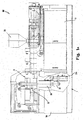
- a machine (M) is composed of a bearing frame (1), capable of guaranteeing the rigidity necessary for the whole machinery and provided with guard panels (10) and access doors (11) for inspection and maintenance.
- the above-mentioned frame (1) supports a plasticising/injecting assembly (2) for plastification of the raw material and injection of the plasticised material into the injection mould, as better detailed in the following.
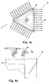
- Fig. 1B illustrates an injection moulding station (3), a blow moulding station (4), handling equipment (index table, 5) for transferring the products in the course of the processing stages and unloading elements (6) for the finished products.
- a machine for moulding plastic objects with the injection blow moulding technique according to this invention includes:
- the plasticising/injecting unit (2), the injection moulding station (3), the blow moulding station (4) and the handling means (5) are driven by electric motors and are thus totally free from hydraulic type components such as, for example, cylinders, control stations, conduits, etc.
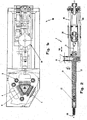
- the above-mentioned assembly (2) includes elements for plastification of the raw material and injection of the plasticised material.
- the raw material is introduced in solid state, that is, in pellets, into a feed hopper (20) standing over the frame (1).
- the hopper (20) is placed on top and connected with a hollow body (22), which is subjected to the action of electric heating elements (not illustrated) and houses a reciprocating screw (21) in its inner cavity.
- the reciprocating screw (21) is driven by an electric motor (see arrow R, Fig. 2); it can revolve around its longitudinal axis (a-a) and be moved longitudinally along this axis (see arrow W in Fig. 2), that is, parallel to guides (26), because it is driven by an electric motor (25) connected with it by a ball screw (28).
- the raw material in pellet form falls by gravity from the hopper (20) down to the reciprocating screw (21) inside the injector body (22).
- the mechanical action of the reciprocating screw (21), that is, the interaction of the reciprocating screw with the inner walls of the body (22) and the heating of the hollow body (22) turn the raw material into fluid state.
- the reciprocating screw (21) conveys the raw material, originally in pellets and later in fluid state, towards the injection front end (29) of the hollow body (22).
- the reciprocating screw (21) retracts from the above-mentioned front end (with a movement to the right in the reference mark visible in Fig. 2), and forms, in correspondence with the above-mentioned injection end (29), a chamber (27) full of fluidised plastic.
- the volume of the chamber (27) can be modified depending on the type of mould into which to inject the plastic; in other words, by lengthening or shortening the excursion of the reciprocating screw (21) inside the hollow body (22), a larger or smaller volume of fluidised plastic to be injected will be determined.
- the reciprocating screw (21) will be driven in reverse direction to the one it had so far, allowing the plastic to flow from the chamber (27) into the injection moulds on the injection moulding station (3).
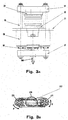
- the injection moulding station (3) includes a mould supporting table (31), on which there rests the bottom part of the injection mould (32).
- a cross beam (34) supports the upper part of the injection mould (33) from the top.
- Columns (35) with wedges are arranged vertically.
- the upper part of the mould (33) In starting condition, the upper part of the mould (33) must be in raised position. Then, the upper mould (33) is lowered by a rigid bridge consisting of the upper cross beam (34), of the columns with wedges (35) and of the lower cross beam (37).
- the bridge movement is guaranteed by a ball screw (38) connected with a motor (309) by a belt transmission (310).
- the belt (310) through the ball screw (38) induces the revolution of the shaft (380), connected with the ball screw (38) and, consequently, lowers the above-mentioned rigid bridge.
- the kinematic connection between gear motor (314) and lead screws (311) consists of a gear (316), which belongs to a transmission (313) and is hinged with two ends of two connecting rods (312), whose opposed ends are hinged with the lead screws (311).
- the injection moulding station is advantageously provided with a gear motor (315) connected with a relative electric motor (351).
- the gear motor (315) allows regulation of the height of the moulds through two threads (not illustrated) present on the columns with wedges (35), thus maintaining the locking position constant, a gear transmission being provided between the electric motor (351) and the said threads.
- This type of mould locking feature is a novelty for this type of machines, which usually receive power via toggle lever systems or via direct power transmission.
- the blow mould closing system is built in an analogous way as described for the injection moulding station (3); one difference consists in the size of the motor that drives the mould locking elements; in fact, this motor is remarkably smaller because of the lower power needed.
- the maximum load capacity of the system is 10 tons.
- the mould locking system is a novelty for this type of machines, which usually receive power by means of toggle lever systems or by direct power transmission.
- the handling index table (5) has the function to convey the product through the various processing phases, making it transit between the different operating stations of the machine.
- the index table (5) includes an upper part (51) that supports a bar (52); this bar carries more than one male rod (53).
- Each male rod (53) present in the injection moulding station (3) in a way in itself known, has the task of acting as the internal shape around which the plastic material, injected into the mould, spreads. In practice, in the injection phase, the male rod (53) appears interposed between the upper half (33) and the lower half (32) of the injection mould.
- the task of the male rod (53) is to support the container and to act as a blowing nozzle, whereas in the unloading station (4) it has the task of supporting the finished container.
- the product handling function of the index table (5) is substantially the same as in the machines of the known technique.
- the index table (5) is provided with handling means that allow the passage of male rods (53) thorough the different processing stations.
- This purpose is achieved by an indexer gear box (54) with a relative motor (540) for the index table rotary motion drive; they determine the rotary motion of the index table in known manner.
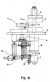
- levers (55) connect the index table (5) with a bracket (59) (visible in Fig. 6 in proximity to the lower cross beam (37)) of the injection moulding station (3). In this way, the same electrical motor (314) that drives the injection mould locking system is used.
- the lowering movement of the index table (5) can be advantageously achieved by a cylinder (56), that can be operated via appropriate means of actuation when manual intervention is called for.
- this station As concerns the unloading station (6), this station, as mentioned before, has the task of extracting the finished containers from the male rods and of unloading the containers by dropping them.
- the unloading station functions in the same way as foreseen on machines of the know technique and, for this reason, is not described in detail.
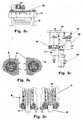
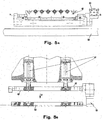
- the extractor cylinders (61) command the traverse movement of the extractor bar (62) which, in turn, extracts the containers from the relative male rods (53) and brings them to the unloading position.
- the traverse movement is indicated by an arrow (V) in Fig. 5B.
- the containers are rotated by the cylinder (63) around the axis (b-b) and arranged vertically; the rotation operated by the cylinder (63) is represented by an arrow (K) in Fig. 5C.
- the extractor cylinders (61) are then retracted and the mechanical contact between the container and the unloading stop limit (64) allows the containers to be removed from the extractor bar (62).
- the unloading station drive cylinders are of pneumatic type; therefore, also in this station there are no hydraulic drive components installed.
Landscapes
- Engineering & Computer Science (AREA)
- Manufacturing & Machinery (AREA)
- Mechanical Engineering (AREA)
- Blow-Moulding Or Thermoforming Of Plastics Or The Like (AREA)
Priority Applications (1)
| Application Number | Priority Date | Filing Date | Title |
|---|---|---|---|
| EP02425358A EP1366885A1 (fr) | 2002-05-31 | 2002-05-31 | Dispositif pour fabriquer des objets en matière plastique |
Applications Claiming Priority (1)
| Application Number | Priority Date | Filing Date | Title |
|---|---|---|---|
| EP02425358A EP1366885A1 (fr) | 2002-05-31 | 2002-05-31 | Dispositif pour fabriquer des objets en matière plastique |
Publications (1)
| Publication Number | Publication Date |
|---|---|
| EP1366885A1 true EP1366885A1 (fr) | 2003-12-03 |
Family
ID=29414875
Family Applications (1)
| Application Number | Title | Priority Date | Filing Date |
|---|---|---|---|
| EP02425358A Withdrawn EP1366885A1 (fr) | 2002-05-31 | 2002-05-31 | Dispositif pour fabriquer des objets en matière plastique |
Country Status (1)
| Country | Link |
|---|---|
| EP (1) | EP1366885A1 (fr) |
Cited By (2)
| Publication number | Priority date | Publication date | Assignee | Title |
|---|---|---|---|---|
| EP2199061A1 (fr) * | 2008-12-19 | 2010-06-23 | Krones AG | Machine de formage par soufflage entraînée de manière électrique et le procédé |
| CN114161684A (zh) * | 2021-11-25 | 2022-03-11 | 安徽银泰塑业有限公司 | 一种药瓶加工用注吹中空成型机 |
Citations (5)
| Publication number | Priority date | Publication date | Assignee | Title |
|---|---|---|---|---|
| EP0328658A1 (fr) * | 1987-07-17 | 1989-08-23 | Nissei Asb Machine Co., Ltd. | Machine de moulage rotative |
| EP0794045A1 (fr) * | 1996-03-06 | 1997-09-10 | Husky Injection Molding Systems Ltd. | Machine à tourelle pour mouler des articles |
| DE19909307A1 (de) * | 1998-03-19 | 1999-09-23 | Siemens Ag | Produktionsmaschine mit elektrischen Antrieben für den Einsatz in der Kunststoffindustrie |
| EP1018421A2 (fr) * | 1998-12-10 | 2000-07-12 | Sumitomo Heavy Industries, Ltd. | Procédé de contrôle de l'injection pour une presse de moulage |
| WO2001034368A2 (fr) * | 1999-11-11 | 2001-05-17 | Mauser-Werke Gmbh & Co. Kg | Machine de moulage par soufflage |
-
2002
- 2002-05-31 EP EP02425358A patent/EP1366885A1/fr not_active Withdrawn
Patent Citations (5)
| Publication number | Priority date | Publication date | Assignee | Title |
|---|---|---|---|---|
| EP0328658A1 (fr) * | 1987-07-17 | 1989-08-23 | Nissei Asb Machine Co., Ltd. | Machine de moulage rotative |
| EP0794045A1 (fr) * | 1996-03-06 | 1997-09-10 | Husky Injection Molding Systems Ltd. | Machine à tourelle pour mouler des articles |
| DE19909307A1 (de) * | 1998-03-19 | 1999-09-23 | Siemens Ag | Produktionsmaschine mit elektrischen Antrieben für den Einsatz in der Kunststoffindustrie |
| EP1018421A2 (fr) * | 1998-12-10 | 2000-07-12 | Sumitomo Heavy Industries, Ltd. | Procédé de contrôle de l'injection pour une presse de moulage |
| WO2001034368A2 (fr) * | 1999-11-11 | 2001-05-17 | Mauser-Werke Gmbh & Co. Kg | Machine de moulage par soufflage |
Cited By (4)
| Publication number | Priority date | Publication date | Assignee | Title |
|---|---|---|---|---|
| EP2199061A1 (fr) * | 2008-12-19 | 2010-06-23 | Krones AG | Machine de formage par soufflage entraînée de manière électrique et le procédé |
| EP2263855A3 (fr) * | 2008-12-19 | 2011-10-19 | Krones AG | Machine de formage par soufflage entraînée de manière électrique et le procédé |
| US8287797B2 (en) | 2008-12-19 | 2012-10-16 | Krones Ag | Electrically driven blow molding machine |
| CN114161684A (zh) * | 2021-11-25 | 2022-03-11 | 安徽银泰塑业有限公司 | 一种药瓶加工用注吹中空成型机 |
Similar Documents
| Publication | Publication Date | Title |
|---|---|---|
| US7798798B2 (en) | Rotary injection molding apparatus and method for use | |
| CA2898689C (fr) | Appareil d'injection-compression pour fabriquer des recipients thermoplastiques | |
| RU2640537C2 (ru) | Литейная форма для пластиковой заготовки | |
| US4726756A (en) | Temperature control blow molding equipment in injection stretch blow molding machine | |
| EP0328658B1 (fr) | Machine de moulage rotative | |
| JP2005511347A (ja) | プラスチック物品の圧縮成形のための装置および方法 | |
| CN107571459A (zh) | 一种便于成品收集的新型模具 | |
| EP2945791B1 (fr) | Joint rotatif pour transférer du plastique fondu | |
| SU753351A3 (ru) | Устройство дл лить под давлением полимерных материалов | |
| WO1996030192A1 (fr) | Machine et procede de moulage par injection-soufflage | |
| CN100377856C (zh) | 用于压缩成形塑料容器的装置和方法 | |
| EP1366885A1 (fr) | Dispositif pour fabriquer des objets en matière plastique | |
| KR20180128999A (ko) | 블로우 성형방법 | |
| JP6007833B2 (ja) | 回転式製造装置 | |
| CN213472306U (zh) | 一种片剂压片装置 | |
| CN109774102A (zh) | 一种基于吹塑成型技术的高效型自动化塑料桶生产系统 | |
| EP3628465B1 (fr) | Machine de moulage par injection en plastique et procédé de moulage | |
| CN219153624U (zh) | 一种具备导向功能的注塑顶出装置 | |
| CN118438641A (zh) | 一种注塑吹瓶一体机 | |
| CN111055475A (zh) | 一种基于吹塑成型技术的便于固定的塑料桶生产设备 | |
| CN100592974C (zh) | 设有多个致动装置的操作机,设备和控制系统 | |
| CN209718540U (zh) | 一种便于取出废料的塑料吹出机 | |
| CN222246050U (zh) | 一种注塑吹瓶一体机 | |
| CN112277275A (zh) | 一种塑料制品的模具加工方法及装置 | |
| CN119974389B (zh) | 一种便于拆卸清理的塑料瓶胚体注塑装置 |
Legal Events
| Date | Code | Title | Description |
|---|---|---|---|
| PUAI | Public reference made under article 153(3) epc to a published international application that has entered the european phase |
Free format text: ORIGINAL CODE: 0009012 |
|
| AK | Designated contracting states |
Kind code of ref document: A1 Designated state(s): AT BE CH CY DE DK ES FI FR GB GR IE IT LI LU MC NL PT SE TR |
|
| AX | Request for extension of the european patent |
Extension state: AL LT LV MK RO SI |
|
| 17P | Request for examination filed |
Effective date: 20040318 |
|
| RAP1 | Party data changed (applicant data changed or rights of an application transferred) |
Owner name: MECCANOPLASTICA S.R.L. |
|
| AKX | Designation fees paid |
Designated state(s): AT BE CH CY DE DK ES FI FR GB GR IE IT LI LU MC NL PT SE TR |
|
| AXX | Extension fees paid |
Extension state: SI Payment date: 20040318 Extension state: RO Payment date: 20040318 |
|
| 17Q | First examination report despatched |
Effective date: 20040730 |
|
| RAP1 | Party data changed (applicant data changed or rights of an application transferred) |
Owner name: MECCANOPLASTICA S.R.L. Owner name: U.T.E. PROGETTI S.R.L. |
|
| STAA | Information on the status of an ep patent application or granted ep patent |
Free format text: STATUS: THE APPLICATION IS DEEMED TO BE WITHDRAWN |
|
| 18D | Application deemed to be withdrawn |
Effective date: 20050806 |