EP1366932A1 - Detecteur de pression pneumatique de pneu - Google Patents
Detecteur de pression pneumatique de pneu Download PDFInfo
- Publication number
- EP1366932A1 EP1366932A1 EP02711326A EP02711326A EP1366932A1 EP 1366932 A1 EP1366932 A1 EP 1366932A1 EP 02711326 A EP02711326 A EP 02711326A EP 02711326 A EP02711326 A EP 02711326A EP 1366932 A1 EP1366932 A1 EP 1366932A1
- Authority
- EP
- European Patent Office
- Prior art keywords
- status value
- air pressure
- tire air
- rotational
- wheel speed
- Prior art date
- Legal status (The legal status is an assumption and is not a legal conclusion. Google has not performed a legal analysis and makes no representation as to the accuracy of the status listed.)
- Withdrawn
Links
- 230000007423 decrease Effects 0.000 claims abstract description 155
- 238000001514 detection method Methods 0.000 claims abstract description 75
- 230000003466 anti-cipated effect Effects 0.000 claims abstract description 4
- 238000012545 processing Methods 0.000 claims description 189
- 230000000694 effects Effects 0.000 claims description 54
- 238000012886 linear function Methods 0.000 claims description 14
- 238000004364 calculation method Methods 0.000 description 33
- 230000000875 corresponding effect Effects 0.000 description 22
- 238000010586 diagram Methods 0.000 description 22
- 238000012935 Averaging Methods 0.000 description 10
- 238000000034 method Methods 0.000 description 10
- 230000003247 decreasing effect Effects 0.000 description 9
- 238000005096 rolling process Methods 0.000 description 8
- 238000010276 construction Methods 0.000 description 2
- 230000002596 correlated effect Effects 0.000 description 2
- 230000006870 function Effects 0.000 description 2
- 238000005259 measurement Methods 0.000 description 2
- 238000002474 experimental method Methods 0.000 description 1
- 238000012986 modification Methods 0.000 description 1
- 230000004048 modification Effects 0.000 description 1
Images







Classifications
-
- B—PERFORMING OPERATIONS; TRANSPORTING
- B60—VEHICLES IN GENERAL
- B60C—VEHICLE TYRES; TYRE INFLATION; TYRE CHANGING; CONNECTING VALVES TO INFLATABLE ELASTIC BODIES IN GENERAL; DEVICES OR ARRANGEMENTS RELATED TO TYRES
- B60C23/00—Devices for measuring, signalling, controlling, or distributing tyre pressure or temperature, specially adapted for mounting on vehicles; Arrangement of tyre inflating devices on vehicles, e.g. of pumps or of tanks; Tyre cooling arrangements
-
- B—PERFORMING OPERATIONS; TRANSPORTING
- B60—VEHICLES IN GENERAL
- B60C—VEHICLE TYRES; TYRE INFLATION; TYRE CHANGING; CONNECTING VALVES TO INFLATABLE ELASTIC BODIES IN GENERAL; DEVICES OR ARRANGEMENTS RELATED TO TYRES
- B60C23/00—Devices for measuring, signalling, controlling, or distributing tyre pressure or temperature, specially adapted for mounting on vehicles; Arrangement of tyre inflating devices on vehicles, e.g. of pumps or of tanks; Tyre cooling arrangements
- B60C23/06—Signalling devices actuated by deformation of the tyre, e.g. tyre mounted deformation sensors or indirect determination of tyre deformation based on wheel speed, wheel-centre to ground distance or inclination of wheel axle
- B60C23/061—Signalling devices actuated by deformation of the tyre, e.g. tyre mounted deformation sensors or indirect determination of tyre deformation based on wheel speed, wheel-centre to ground distance or inclination of wheel axle by monitoring wheel speed
Definitions
- the present invention relates to a device for detecting tire air pressure based on a vehicle speed signal.
- JP-A-H7-125512 discloses a conventional tire air pressure detection device.
- the tire air pressure device can detect an accurate tire air pressure by removing an effect of tread-lift.
- Tread-lift is a phenomenon wherein a dynamic rolling radius of a tire in which tire air pressure has decreased becomes approximately the same as that of a tire in which tire air pressure has not decreased because the radius of tire increases due to a centrifugal force.
- a determination value for determining tire air pressure decrease is erroneously determined because the dynamic rolling radius of the tire in which tire air pressure has decreased becomes approximately the same as that of a tire of which tire air pressure has not decreased. That is, the determination value for determining tire air pressure decrease varies to close that of a determination value of the tire of which tire air pressure has not decreased. As a result, tire air pressure is not detected accurately.
- an air pressure detection device checks a relationship between vehicle speed correlating with the centrifugal force and a determination value for determining the tire air pressure (e.g., a rotational status value), and stores the relationship in memory.
- a determination value for determining the tire air pressure e.g., a rotational status value
- a degree of the effect of the tread-lift also varies with respect to the tire air pressure.
- a relationship between the tire air pressure and the effect of the tread-lift is shown in FIG. 22.
- JP-A-H10-100624 also discloses a conventional tire air pressure detection device.
- the tire air pressure device detects a decrease in tire air pressure based on wheel speed variation D and a front and rear wheel speed ratio ⁇ .
- the wheel speed variation D and the front and rear wheel speed ratio ⁇ are expressed as follows, where V FR corresponds to front right wheel speed, V FL corresponds to front left wheel speed, V RR corresponds to rear right wheel speed and V RL corresponds to rear left wheel speed.
- the wheel speed variation D represents a rotational status value calculated based on wheel speeds of four vehicle wheels.
- the wheel speed variation D is a variable defined as a difference of wheel speed ratios of each pair of wheels located diagonally from each other, and increases or decreases when the tire air pressures of some of the vehicle wheels decrease.
- the front and rear wheel speed ratio ⁇ is a tire slip status value that denotes a degree of slip status of driven wheels caused by transmitted driving forces. For example, the smaller the front and rear wheel speed ratio ⁇ is, the higher the slip of one (or both) of the driven wheels is.
- the wheel speed variation D increases or decreases when the tire air pressures of some of the vehicle wheels decreases below a standard value, and it is zero when each tire air pressure of each tire equals the standard value. Therefore, the tire pressure decrease is detected based on the wheel speed variation D.
- the wheel speed variation D varies based on the degree of slip status of the wheels.
- a regression line is calculated based on a relationship of the front and rear wheel speed ratio ⁇ and the wheel speed variation D using a minimum square calculation methodology.
- An ideal value of the wheel speed variation D is then calculated by compensating for the wheel speed variation D (or an average D AVE ).
- An ideal value of the wheel speed variation D is a value of the wheel speed variation D if the slip does not occur when the front and rear wheel speed ratio ⁇ is 1.
- the wheel speed variation D varies based on the effect of the tread-lift as well as the slip of the driven wheels.
- a calculation result of the wheel speed variation D is plotted using white circles ( ⁇ ) separately from black circles ( ⁇ ) that indicates a wheel speed variation D when the effect of the tread-lift is not generated. Therefore, the accuracy of the calculation of the wheel speed variation D decreases, and therefore the warning pressure varies.
- the wheel speed variation D under an ideal driven status is calculated based on the regression line.
- a difference ( ⁇ D'sh) between the wheel speed variation D under the ideal driven status and a predetermined reference value (D' AVE std) is defined as a determination value for determining the tire air pressure decrease.
- the tire air pressure decrease is determined when the determination value exceeds a warning threshold.
- a tire air pressure detection device includes a warning anticipation timing calculating portion (3g) for anticipating a warning timing at which the tire air pressure decrease detecting portion will detect the tire air pressure decrease based on the rotational status value compensated for by a rotational status value compensating portion.
- a tire air pressure decrease detecting portion detects a decrease in tire air pressure when determination time reaches the warning anticipation timing anticipated by the warning anticipation timing calculating portion.
- the tire air pressure detection device can detect a decrease in tire air pressure when the determination time reaches the warning anticipation timing.
- the warning anticipation timing calculating portion calculates a timing when the rotational status compensated for by the rotational status value compensating portion will exceed a predetermined threshold as the warning anticipation timing.
- the warning anticipation timing calculating portion may calculate the warning anticipation timing based on a change in value per predetermined interval of the rotational status compensated for by the rotational status value compensating portion.
- a wheel speed variation (D) corresponding to a difference in wheel speed ratios of wheels located diagonally from each other may be applied as the rotational status value.
- a tire air pressure detection device includes a memory portion (3g) for memorizing warning anticipation timing data calculated by the warning anticipation timing calculating portion.
- the memory portion renews previously stored warning anticipation timing data stored before to new calculated warning anticipation timing data when the new warning anticipation timing data is earlier than the previously stored warning anticipation timing data.
- the warning anticipation timing data is only renewed when an earlier timing is calculated as the warning anticipation timing, although the warning anticipation timing may alternatively be renewed every time. Therefore, the tire air pressure detection device can warn the driver of a tire air pressure decrease at the earliest possible timing.
- the rotational status value compensating portion (3f) calculates an ideal rotational status value when there is no tire slippage based on the regression line calculated by the regression line calculating portion and the ideal slip status value calculated by the ideal driving status calculating portion.
- the tire air pressure detection device calculates the ideal rotational status value based on the regression line and the ideal driving status. Therefore, the tire air pressure detection device can accurately detect a tire air pressure decrease using the ideal rotation status value.
- a tire air pressure detection device has a tread-lift compensation processing portion (3j) for determining whether a determination value ( ⁇ D' AVE ) exceeds a predetermined threshold (Cth) and for compensating for the determination value when the determination value exceeds the predetermined threshold.
- the tire air pressure decrease detecting portion detects a decrease in tire air pressure based on the determination value calculated by the tread-lift compensation processing portion.
- the tire air pressure detection device compensates for the determination value when it exceeds the predetermined threshold compensate, while do not compensate for when it do not exceed the predetermined threshold. That is, the determination value is appropriately compensated for when the effect of tread-lift is large. Therefore, the determination value is prevented from being varied because it is not compensated for when the effect of the tread-lift is small, and thus an appropriate determination value can be calculated. Accordingly, the tire air pressure can be accurately detected.
- a tire air pressure detection device of claim 8 has a tread-lift compensation processing portion (3j) for removing an effect of tread-lift and adjusting a degree of the compensation processing with respect to a scale of the determination value.
- the tire air pressure decrease detecting portion detects that the tire air pressure decreases based on the determination value compensated by the compensation processing of the tread-lift compensation processing portion. For example, as in claim 9, the compensation degree becomes large by the tread-lift compensation processing portion when the effect of tread-lift is large.
- a degree of compensation of the determination value is adjusted with respect to an offset amount of the determination value. Therefore, the compensation degree increases when the effect of tread-lift is large, and decreases when the effect of tread-lift is small. As a result, an appropriate determination value can be calculated, and the tire air pressure can be accurately detected.
- the compensation methodology is executed after an initializing mode at which a post-compensation rotational status value is not yet calculated by a rotational status value calculating portion.
- the compensation methodology is not executed during an initializing mode. Accordingly, the determination value is not compensated for while a reference value ( ⁇ D' AVE std) is calculated when respective tire air pressures of respective vehicle wheels are identical. Therefore, initializing mode processing is appropriately executed.
- the determination value ( ⁇ D'' AVE ) may be a difference between a post-compensation value calculated at the initializing mode and that calculated after the initializing mode.
- a tire air pressure detection device includes a vehicle wheel speed detecting portion (2a-2d, 3a) for detecting respective vehicle wheel speeds; a rotational status value calculating portion (3b) for calculating a rotational value (D) expressing a relationship of the respective vehicle wheel speeds to cancel a wheel speed variation between left and right wheels generated due to vehicle turns; a first rotational status value compensation portion (3n) for compensating for the rotational status value calculated by the rotational status value calculating portion using vehicle speed as a parameter; a slip status value calculating portion (3c) for calculating a slip status value ( ⁇ ) based on the vehicle wheel speeds detected by the vehicle wheel speed detecting portion, the slip status value depending on a slip status between driven wheels and non-driven wheels; a regression line calculating portion (3d) for calculating a regression line that is a linear function expressing a relationship between the rotational status value (D*) compensated for by the first rotational status value compensating portion and the slip status value calculated by the slip status value calculating portion; a second rotational
- the rotational status value in which the effect of tread-lift is removed is calculated by compensating for rotational data within short intervals using vehicle speed as a parameter.
- the regression line indicating a relationship between the rotational status value and the slip status value based on the above mentioned rotational status value. Further, a compensated rotational status value in which the slippage effect of the driven wheels is removed based on the regression line.
- the tire air pressure device can detect a decrease of tire air pressure based on the compensated rotational status value in which the slippage effect of the driven wheels is removed and the effect of tread-lift is removed. It is possible to detect the tire air pressure decrease accurately.
- the first rotational status value compensating portion calculates a change in value of rotational status value relative to the vehicle speed based on a relationship between the rotational status value calculated by the rotational status value calculating portion and the vehicle speed, and compensates for the rotational status value by adding the change in value as a compensation value.
- the relationship between the rotational status value and the vehicle speed is, as described in claim 15, calculated by the first rotational status value compensating portion based on the data regarding the rotational status value stored in the rotational status value memorizing portion.
- the rotational status value calculated by the rotational status value calculating portion is compensated for based on a default value indicating a relationship between an predetermined rotational status value and the vehicle speed before the relationship is calculated, while compensated for based on a calculated relationship after it is calculated.
- the rotational status value compensating portion (3f) calculates an ideal rotational status value when there is no tire slippage based on the regression line calculated by the regression line calculating portion and the ideal slip status value calculated by the ideal driving status calculating portion.
- the tire air pressure detection device calculates the ideal rotational status value based on the regression line and the ideal driving status. Therefore, the tire air pressure detection device can accurately detect a tire air pressure decrease using the ideal rotation status value.
- a regression line calculating portion (3d) is for classifying vehicle speed to several speed ranges, distinguishing the rotational status value and the slip status value in each related speed range of the several speed ranges, and calculating a regression line that is a linear function expressing a relationship between the rotational status value calculated by the rotational status value calculating portion and the slip status value calculated by the slip status value calculating portion at each of the several speed ranges.
- a rotational status value compensating portion (3f) is for compensating for the rotational status value calculated by the rotational status value calculating portion based on the regression line calculated at each speed range by the regression line calculating portion.
- a tire air pressure decrease detecting portion (3h) is for calculating a regression curve based on the rotational status value of each speed range compensated for by the rotational status value compensating portion, and for detecting a tire air pressure decrease based on a determination value ( ⁇ D''' AVE ) that is defined based on the rotational status value ( ⁇ D' AVE )at the each speed range compensated for by the rotational status value compensating portion.
- the effect of tread-lift is removed after the effect of slip is removed.
- a tire air pressure detection device of claim 18 includes a memory portion (3n) for distinguishing and memorizing the data of the rotational status value calculated by the rotational status value calculating portion and the slip status value calculated by the slip status value calculating portion at the each speed range; and a counter for counting each interval since the data has been stored in the memory portion.
- the memory portion deletes the data when the interval reaches a predetermined time. According to the tire air pressure detection device, when tire air pressures begin to decrease, the regression line is not calculated using old data such as data calculated prior to a decrease in tire air pressure.
- a tire air pressure detection device is for detecting a decrease in tire air pressure of one or more of the vehicle wheels and for warning a driver.
- the tire air pressure detection device is applicable to both front or rear wheel drive vehicles. However, in the present embodiment, the tire air pressure device will be described with reference to a rear wheel drive vehicle.
- the tire air pressure detection device includes vehicle wheel speed sensors 2a, 2b, 2c and 2d, which are located around respective vehicle wheels 1a, 1b, 1c and 1d, a central processing unit (CPU) 3 and a warning device 4.
- the CPU 3 receives input signals from the vehicle wheel speed sensors 2a-2d and determines whether tire air pressure in one or more of the vehicle wheels 1a-1d decreases to output a warning signal to the warning device 4.
- the vehicle speed sensors 2a-2d correspond to vehicle speed detecting portions.
- the vehicle wheel speed sensors 2a, 2b respectively detect and output wheel speed signals of respective non-driven wheels (i.e., left and right front wheels).
- the vehicle wheel speed sensors 2c, 2d detect and output wheel speed signals of respective driven wheels (i.e., left and right rear wheels).
- the CPU 3 is a microcomputer or the like for calculating respective values based on detected signals from the vehicle wheel speed sensors 2a-2d and is constructed as follows.
- the CPU 3 includes a vehicle wheel speed calculation portion 3a and a vehicle wheel speed variation processing portion 3b.
- the vehicle wheel speed calculation portion 3a calculates respective vehicle wheel speeds of respective wheels 1a-1d based on detected signals (e.g., pulse signals) from the vehicle wheel speed sensors 2a-2d.
- the vehicle wheel speed variation processing portion 3b includes a vehicle speed variation calculating portion corresponding to a rotation status value calculating portion, a first vehicle speed variation memorizing portion, and a vehicle speed variation average processing portion. Results calculated by the vehicle wheel speed variation processing portion 3b are used for calculating a relative vehicle speed variation D.
- the wheel speed calculating portion 3a calculates the respective vehicle wheel speeds of the respective wheels 1a-1d based on detected signals from the vehicle wheel speed sensors 2a-2d. For example, respective vehicle wheel speeds V FL , V FR , V RL and V RR are calculated based on signals from the vehicle wheel speed sensors 2a-2d inputted over several seconds.
- the vehicle wheel speed variation calculating portion then calculates a wheel speed variation D using the above-mentioned equation (1) based on data corresponding to calculated vehicle wheel speeds.
- the resultant data of the wheel speed variation D is stored in a memory included in the first wheel speed variation memorizing portion.
- the wheel speed variation average processing portion calculates an average value D AVE of the wheel speed variation D based on the resultant data of the wheel speed variation D.
- the average value D AVE of the wheel speed variation D corresponds to the average of n 0 portions of the wheel speed variation D expressed as the following equation.
- D AVE 1 n 0 SD(N)
- the CPU 3 includes a front and rear wheel speed ratio processing portion 3c.
- the front and rear wheel speed ratio processing portion 3c includes a front and rear wheel speed ratio calculating portion corresponding to a slip status value calculating portion, a front and rear wheel speed ratio memorizing portion, and a front and rear wheel speed ratio average processing portion.
- the front and rear wheel speed ratio calculating portion calculates a front and rear wheel speed ratio ⁇ using the above-mentioned equation (2) based on data from the wheel speed calculating portion 3a.
- the resultant data of the front and rear wheel speed ratio ⁇ is stored in a memory included in the front and rear wheel speed ratio memorizing portion.
- the front and rear wheel speed ratio average processing portion calculates the average value ⁇ AVE of the front and rear wheel speed ratio ⁇ based on the resultant data of the front and rear wheel speed ratio ⁇ .
- the CPU 3 also includes a slip variation calculating portion 3d, an ideal driving status value calculating portion 3e, and a wheel speed variation compensating processing portion 3f.
- the slip variation calculation portion 3d calculates slip variation A based on the wheel speed variation D calculated by the wheel speed variation calculating portion of the wheel speed variation processing portion 3b, and the front and rear wheel speed ratio ⁇ calculated by the front and rear wheel speed ratio calculating portion of the front and rear wheel speed ratio processing portion 3c.
- the slip variation A corresponds to the change in value ( ⁇ D/ ⁇ ) of the wheel speed variation D with respect to the front and rear wheel speed ratio ⁇ and is calculated by a minimum square calculation methodology using n 0 portions of the wheel speed variation D and the front and rear wheel speed ratio ⁇ .
- the slip variation calculating portion 3d corresponds to a regression line calculating portion.
- the ideal driving status value calculating portion 3e calculates an ideal driving status value ⁇ id based on calculation results of the slip variation calculating portion 3d.
- the wheel speed variation compensating processing portion 3f includes a wheel speed variation compensating portion and a second wheel speed variation memorizing portion.
- the wheel speed variation compensating portion corresponds to a rotational status value compensating portion.
- the wheel speed variation compensating portion calculates a post-compensation wheel speed variation D' AVE based on the average value D AVE of the wheel speed variation D for each wheel, the average value ⁇ AVE of the front and rear wheel speed ratio ⁇ , the slip variation A, and the ideal driving status value ⁇ id.
- the second wheel speed variation memorizing portion selects and stores a reference value D' AVE std based on the post-compensation wheel speed variation D' AVE .
- the reference value D' AVE std corresponds to post-compensation wheel speed variation D' AVE when tire air pressures of four wheels are identical to be used for a reference value in determining tire air pressure decrease.
- the reference value D' AVE std is calculated based on the average value D AVE of the wheel speed variation D for each wheel, the average value ⁇ AVE of the front and rear wheel speed ratio ⁇ , the slip variation A, and the ideal driving status value ⁇ id calculated based on the wheel speed variation D and the front and rear wheel speed ratio ⁇ calculated immediately after the CPU 3 starts.
- the CPU 3 further includes a warning anticipation timing calculating portion 3g and a tire air pressure decrease determination portion 3h.
- the warning anticipation timing calculating portion 3g calculates a warning anticipation timing based on the reference value D' AVE std stored in the second wheel speed variation memorizing portion and the post-compensation wheel speed variation D' AVE calculated by the wheel speed variation compensating portion, and stores the warning anticipation timing data.
- tire air pressure decrease ratio is calculated based on a change of the post-compensation wheel speed variation D' AVE .
- a timing of which the post-compensation wheel speed variation D' AVE exceeds a predetermined warning threshold is then anticipated based on the tire air pressure decrease ratio and is stored as the warning anticipation timing.
- the tire air pressure decrease determination portion 3h determines whether a determination time reaches the warning anticipation timing to determine the tire air pressure decrease. Specifically, when the determination time reaches the warning anticipation timing, the tire air pressure decrease determination portion 3h transmits a warning signal denoting a tire air pressure decrease to the warning device 4.
- the warning device 4 warns the driver of the tire air pressure decrease by causing a warning light equipped in a vehicle passenger compartment to blink when the warning signal is transmitted thereto.
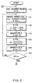
- FIGS. 2 and 3 are flow diagrams showing tire air pressure detecting processing.
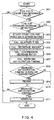
- FIG. 4 is a flow diagram showing warning determination processing.
- the wheel speed calculating portion 3a calculates respective vehicle wheel speeds V FL , V FR , V RL and V RR .
- the CPU 3 then increases the wheel speed calculation number N.
- the processing calculates respective wheel speed averages of each wheel every several minutes based on wheel speed pulses during the several minutes.
- the wheel speed variation calculating portion of the vehicle wheel speed processing portion 3b calculates the wheel speed variation D.
- the wheel speed variation D is calculated by substituting the respective vehicle wheel speeds V FL , V FR , V RL and V RR calculated at 101 into the equation (1).
- the first wheel speed variation memorizing portion stores the wheel speed variation D calculated at 102 to add memorized wheel speed variations D(N).
- D(N) corresponds to an arrangement of n 0 memorized portions of the wheel speed variation D stored in a position of the memory corresponding to a wheel speed calculation number.
- the first wheel speed variation memorizing portion re-stores a new wheel speed variation D in the position of the memory corresponding to wheel speed calculation number N when, for example, the wheel speed calculation number N is reset at 100 after the n 0 portions of the wheel speed variation D are stored.
- the front wheel speed ratio calculating portion of the front wheel speed ratio processing portion 3c calculates a front and rear wheel speed ratio ⁇ .
- the front and rear wheel speed ratio ⁇ is also calculated by substituting the respective vehicle wheel speeds V FL , V FR , V RL and V RR calculated at 101 into the equation (2).
- the memory of the front and rear wheel speed ratio memorizing portion stores the front and rear wheel speed ratio ⁇ calculated at 104 to add memorized front and rear wheel speed ratios ⁇ (N).
- ⁇ (N) corresponds to an arrangement of n 0 memorized portions of the front and rear wheel speed ratio ⁇ stored in a position of the memory corresponding to a wheel speed calculation number.
- the front and rear wheel speed ratio memorizing portion re-stores a new front and rear wheel speed ratio ⁇ in the position of the memory corresponding to wheel speed calculation number N as well as the D(N) after the n 0 portions of the front and rear wheel speed ratio ⁇ are stored.
- the CPU 3 determines whether the wheel speed calculation number N is larger than n 0 .
- the processing advances to 107 when a determination at 106 is positive because n 0 portions of the wheel speed variation D and the front and rear wheel speed ratio ⁇ are stored, while returning at 101 when the determination at 106 is negative.
- the slip calculating portion 3d calculates a slip variation A. That is, a regression line corresponding to linear function of the wheel speed variation D and the front and rear wheel speed ratio ⁇ is calculated, and therefore the slip variation A is calculated based on the regression line.
- the slip variation A expresses a degree of dependency of the wheel speed variation D with respect to the front and rear wheel speed ratio ⁇ .
- the wheel speed variation averaging portion of the wheel speed variation processing portion 3b calculates an average value D AVE of the wheel speed variation D.
- the average value D AVE of the wheel speed variation D is calculated by substituting respective wheel speed variations D memorized at 103 into equation (3).
- the front and rear wheel speed ratio averaging processing portion of the front and rear wheel speed ratio processing portion 3c calculates an average value ⁇ AVE of the front and rear wheel speed ratio ⁇ stored in the memory.
- the average of the front and rear wheel speed ratio ⁇ is calculated by substituting respective front and rear wheel speed ratio ⁇ memorized at 105 into equation (4).
- the ideal driving status value calculating portion 3e calculates an ideal driving status value ⁇ id.
- the ideal driving status value ⁇ id is calculated based on the linear function, quadric function or the like of the slip variation A calculated at 110.
- the wheel speed variation compensating portion of the wheel speed variation compensating processing portion 3f calculates a post-compensation wheel speed variation D' AVE by substituting the average value D AVE , the average value ⁇ AVE , the slip variation A, and the ideal driving status value ⁇ id calculated at 107-110 respectively into equation (5).
- a relationship between the post-compensation wheel speed variation D' AVE and each value (the value D AVE , the slip variation A, the ideal driven status value ⁇ id, and the average value ⁇ AVE ) for calculating the post-compensation wheel speed variation D' AVE is shown in FIG. 5.
- FIG. 5 shows a relationship between the wheel speed variation D and the front and rear wheel speed ratio ⁇ when tire air pressure of one of the driven wheels 1c, 1d (e.g., the left rear wheel) decreases.
- white circles ( ⁇ ) indicate n 0 portions of the relationship between the wheel speed variation D and the front and rear wheel speed ratio ⁇
- black circles ( ⁇ ) indicate a relationship between the average value D AVE of the wheel speed variation D and the average value ⁇ AVE of the front and rear wheel speed ratio ⁇ .
- a regression line corresponding to a linear function of n 0 portions of the wheel speed variation D and the front and rear wheel speed ratio ⁇ is calculated using a minimum square calculation methodology.
- a post-compensation wheel speed variation D' AVE which corresponds to a wheel speed variation D under ideal driving status when tire air pressure of at least one of the driven wheels 1c, 1d decreases, is calculated.
- the post-compensation wheel speed variation D' AVE can be appropriately calculated without excessive compensation.
- the CPU 3 determines whether the reference value D' AVE std has already been determined.
- the processing determines whether the reference value D' AVE std is stored in the memory of the second wheel speed variation memorizing portion of the wheel speed variation compensating processing portion 3f. If the post-compensation wheel speed variation D' AVE is calculated at initially after the CPU 3 starts, the processing advances to 113 to store the post-compensation wheel speed variation D' AVE as a reference value D' AVE std and then returns at 100.
- the warning threshold is defined based on the reference value D' AVE std. For example, a value separating predetermined value D'sh from the reference value D' AVE std is defined as the warning threshold. On the other hand, if the reference value D' AVE std has already been stored, the processing advances to 114.
- warning determining processing is executed by the warning anticipation timing calculating portion 3g and the tire air pressure decrease determination portion 3h.
- the CPU 3 determines whether the post-compensation wheel speed variation D' AVE is lower than the reference value D' AVE std.
- the processing advances to end when a determination at 201 is positive because the tire air pressure does not decrease.
- the processing advances to 202 when the determination at 201 is negative.
- the CPU 3 determines whether a tire air pressure decrease is detected. This is determined base on a count of a counter (not shown) included in the warning anticipation timing calculating portion 3g. For example, a tire air pressure decrease is not detected when the count is 0.
- the processing advances to 203 to start counting by the counter and to reset the data stored before as the warning anticipation timing. Specifically, an infinite timing is set as the warning anticipation timing.
- the processing then advances to 204.
- the processing advances to 204 because the counting has already been started and the warning anticipation timing has been set.
- an elapsed time T from when the detection of tire air pressure detcrease starts is calculated.
- a decrease amount of the post-compensation wheel speed variation D' AVE from when detection starts is calculated.
- tire air pressure decrease ratio per predetermined time interval ( ⁇ D'AVE/ ⁇ T) is calculated based on the elapsed time T and decrease amount of the post-compensation wheel speed variation D' AVE .
- the processing then advances to 207, and a warning anticipation timing at which the post-compensation wheel speed variation D' AVE is lower than the warning threshold is calculated based on the tire air pressure decrease ratio per predetermined time interval.
- the CPU 3 determines whether the warning anticipation timing calculated at 207 is earlier than that stored before in the tire air pressure decrease determination portion 3h.
- the processing advances to 209 when a determination at 208 is positive to replace data of the warning anticipation timing stored in the tire air pressure decrease determination portion 3h with the newly calculated data.
- the processing then advances to 210.
- the processing advances to 210 when the determination is negative.
- the data is only renewed when an earlier timing is calculated as the warning anticipation timing, although the warning anticipation timing may alternatively be renewed every time. This is because an earlier driver warning is preferred.
- the CPU 3 determines whether the determination time reaches the warning anticipation timing.
- the processing advances to 211 when a determination at 210 is positive. Therefore, the tire air pressure decrease determination portion 3h transmits a warning signal denoting tire air pressure decrease to the warning device 4.
- the processing advances to end when a determination is negative. Thus, a tire air pressure decrease of respective wheels 1a-1d can be detected.
- a warning anticipation timing at which a post-compensation wheel speed variation D' AVE is lower than a warning threshold is calculated based on tire air pressure decrease ratio per predetermined time ( ⁇ D'AVE/ ⁇ T). Then, the driver is warned of the tire air pressure decrease when the determination time reaches the warning anticipation timing even if the post-compensation wheel speed variation D' AVE is actually lower than the warning threshold.
- the tire air pressure detection device can detect tire air pressure decrease when the determination time reaches the warning anticipation timing (i.e., an intersection of dotted line and threshold).
- the tire air pressure detection device of the present embodiment data of the warning anticipation timing is only renewed when it will renew earlier timing data. Accordingly, the tire air pressure detection device can warn the driver of a tire air pressure decrease at the earliest possible timing.
- the ideal wheel speed variation value D is calculated under the condition that the front and rear wheel speed ratio ⁇ is 1.
- the front and rear wheel speed ratio ⁇ is not 1 when tire air pressure decrease. Therefore, the above compensation is excessive.
- changes of the wheel speed variation D of the driven wheels and non-driven wheels due to the tire air pressure decrease are different, and a warning pressure, which is a pressure at which a driver is warned, varies.
- the slip variation A is calculated based on a wheel speed variation D and a front and rear wheel speed ratio ⁇ .
- An ideal driving status value ⁇ id is then calculated based on the slip variation A.
- a post-compensation wheel speed variation D' AVE is calculated based on an average value D AVE of the wheel speed variation D of each wheel, an average value ⁇ AVE of the front and rear wheel speed ratio ⁇ , the slip variation A, and the ideal driving status value ⁇ id.
- the post-compensation wheel speed variation D' AVE which corresponds to a wheel speed variation D under an ideal driving status when the tire air pressure of at least one of the driven wheels 1c, 1d decreases, is calculated without excessive compensation.
- the post-compensation wheel speed variation D' AVE when the tire air pressure of the driven wheel decreases and that when the tire air pressure of the non-driven wheel decreases are identical. Therefore, regardless of which wheels decrease in pressure, the warning pressure remains uniform.
- a tire air pressure detection device has a different construction from the first embodiment. As shown in FIG. 7, in this embodiment, the tire air pressure detection device is modified with respect to tire air pressure detection device in the first embodiment.
- a CPU 3 has a pressure difference threshold calculating portion 3i and a difference threshold compensating portion 3j.
- the pressure difference threshold calculating portion 3g calculates a pressure difference determination value ⁇ D' AVE based on the reference value D' AVE std stored in the second wheel speed variation memorizing portion of the wheel speed variation compensating processing portion 3f and the post-compensation wheel speed variation D' AVE calculated by the wheel speed variation compensating portion.
- the pressure difference threshold compensating portion 3j compensates for the pressure difference determination value ⁇ D' AVE calculated at the pressure difference threshold calculating portion 3g. This compensation is basically determined in the same manner as in JP-A-H7-125512, and is described as follows.
- the compensation is executed using an equation expressing a relationship between a square value (V 2 ) of the vehicle speed V and the pressure difference determination value ⁇ D' AVE .
- the relational equation is defined as follows.
- the vehicle speed V is calculated based on vehicle wheel speeds calculated by a vehicle wheel speed calculating portion 3a.
- the vehicle speed V corresponds a wheel speed average V AVE of vehicle wheel speeds V FL , V FR , V RL and V RR .
- the average wheel speed average V AVE is applied for a value that equals to a summation of the vehicle wheel speeds V FL , V FR , V RL and V RR divided by 4 (total wheel number).
- the average wheel speed average V AVE may alternative be applied for a value that equals to a summation of three of the vehicle wheel speeds V FL , V FR , V RL and V RR divided by 3. This is because one of the vehicle wheel speeds V FL , V FR , V RL and V RR may be higher than the others due to the tire air pressure decrease.
- a relationship between the vehicle speed V and the pressure difference determination value ⁇ D' AVE is experimentally measured. That is, a change of the pressure difference determination value ⁇ D' AVE with respect to vehicle speed V is measured after the tire air pressure of one of the four wheels decreases below a standard pressure (e.g., 30% decrease). For example, under the above-mentioned condition, the vehicle is driven at a predetermined speed, and the pressure difference determination value ⁇ D' AVE is repeatedly measured.
- This experimental measurement is practiced at each speed range classified from an available speed range as a vehicle speed. For example, the available speed range from 20km/h to 180km/h is classified to 10km/h range. Thereafter, each average value of the pressure difference determination value ⁇ D' AVE of each classified range is calculated.
- each pressure difference determination value ⁇ D' AVE of each tire with respect to vehicle speed V is determined.
- one of the speed ranges (e.g., 120km/h range) classified as mentioned above is defined as a reference speed V 0 .
- a graph is defined.
- a longitudinal axis of the graph is defined as a ratio Y of the each average value of the pressure difference determination value ⁇ D' AVE to an average value of the pressure difference determination value ⁇ D' AVE of the reference speed V 0 .
- a pressure difference determination value ⁇ D'' AVE after compensation (hereinafter referred to as a post-compensation pressure difference determination value ⁇ D'' AVE ) is calculated by compensating for the pressure difference determination value ⁇ D' AVE calculated by the pressure difference threshold calculating portion 3i during real driving based on the equation expressing the relationship between ratio X and the ratio Y.
- the compensation processing of the pressure difference determination value ⁇ D' AVE against tread-lift is completed.
- the compensation processing is executed when the pressure difference determination value ⁇ D' AVE exceeds a predetermined threshold Cth, but when it is lower than the predetermined threshold Cth (see 123 in FIG. 9).
- the tire air pressure decrease determination portion 3h compares an absolute value
- processing as in the first embodiment is executed. Then, at 112, the processing advances to 121 when the post-compensation wheel speed variation D' AVE is not calculated when the CPU 3 starts.
- the pressure difference threshold calculating portion 3i calculates a pressure difference determination value ⁇ D' AVE that corresponds to a difference between the reference value D' AVE std and the post-compensation wheel speed variation D' AVE .
- the tire air pressure decrease determination portion 3h determines whether an absolute value
- the tire air pressure hardly decreases and the effect of the tread-lift is relatively small when the pressure difference determination value ⁇ D' AVE is not relatively large.
- non-uniformity of the pressure difference determination value ⁇ D' AVE increases if the compensation processing against tread-lift is executed. Accordingly, the processing advances to 123 to execute the compensation processing against tread-lift when a determination at 122 is positive, while returning at 100 when the determination at 122 is negative.
- the difference threshold compensating portion 3j compensates for the pressure difference determination value ⁇ D' AVE . That is, the pressure difference determination value ⁇ D' AVE is compensated for by equation (6) defined based on the relationship of the pressure difference determination value ⁇ D' AVE to the square value (V 2 ) of the vehicle speed V. Thus, the post-compensation pressure difference determination value ⁇ D'' AVE is calculated.
- the tire air pressure decrease determination portion 3h determines whether the absolute value
- the processing advances to 125 to transmit the warning signal to the warning device 4 when a determination at 124 is positive.
- the processing advances to end and returns at 100 when the determination is negative. In the manner, any tire air pressure decreases in the respective vehicle wheels 1a-1d are detected.
- FIG. 10 a timing diagram of the pressure difference determination value ⁇ D' AVE is illustrated in FIG. 10.
- the compensation processing is executed when the pressure difference determination value ⁇ D' AVE exceeds a predetermined threshold Cth, but when it is lower than the predetermined threshold Cth. That is, the compensation processing is executed only when the effect of tread-lift is not negligible. Therefore, it can avoid that non-uniformity of the pressure difference determination value ⁇ D' AVE increases when the compensation processing against tread-lift is executed even if the effect of tread-lift is not large.
- the pressure difference determination value ⁇ D' AVE is appropriately compensated for when the effect of tread-lift is large.
- an appropriate pressure difference determination value can be calculated even if the dynamic rolling radius of the tire increases due to the effect of tread-lift. Therefore, the post-compensation wheel speed variation D' AVE does not close to the reference value D' AVE std, and the tire air pressure can be accurately detected.
- the compensation processing against tread-lift is not executed until the reference value D' AVE std is stored, i.e., until the initializing mode.
- the pressure difference determination value ⁇ D' AVE is not compensated for while the references value D' AVE std is calculated when respective tire air pressure of respective vehicle wheels 1a-1d are identical. Therefore, initializing mode processing is appropriately executed.
- a pressure difference determination value is compensated for in a manner different from the second embodiment.
- the configuration of the tire air pressure detection device of the third embodiment is the same as in the second embodiment, but processing executed in a difference threshold compensating portion 3j is different from the second embodiment.
- the difference threshold compensating portion 3j calculates an equation expressing a relationship between a square value (V 2 ) of the vehicle speed V and a pressure difference determination value ⁇ D' AVE in the same manner as in the second embodiment. The equation is then stored in memory.
- the pressure difference determination value ⁇ D' AVE calculated by the pressure difference threshold calculating portion 3i during driving is compensated for based on the equation. In this case, entire pressure difference determination value ⁇ D' AVE is compensated for even if the pressure difference determination value ⁇ D' AVE does not exceed a predetermined threshold Cth. This processing is different from the second embodiment.
- a degree of compensation of the pressure difference determination value ⁇ D' AVE is adjusted with respect to an offset amount of the pressure difference determination value ⁇ D' AVE . That is, the larger the offset amount of the pressure difference determination value ⁇ D' AVE is, the larger the compensation degree is.
- processing as in the second embodiment is executed.
- the pressure difference determination value ⁇ D' AVE is calculated.
- the processing then advances to 130 to compensate for the pressure difference determination value ⁇ D' AVE .
- This compensation processing for the pressure difference determination value ⁇ D' AVE is executed as mentioned above. Thereafter, the processing advances to 124 and 125 as in the second embodiment.
- the compensation processing against tread-lift is executed when the pressure difference determination value ⁇ D' AVE exceeds a predetermined threshold Cth. Also, in the third embodiment, the compensation degree against tread-lift is adjusted with respect to the offset amount of the pressure difference determination value ⁇ D' AVE . However, compensation processing as in the second and third embodiments is not needed if the compensation processing against tread-lift is not executed during the initializing mode.
- the pressure difference determination value ⁇ D' AVE is compensated for every time as at 123 in the second embodiment.
- the compensation processing against tread-lift as in the second and third embodiment is not executed during the initializing mode.
- the pressure difference determination value ⁇ D' AVE is not compensated for while the reference value D' AVE std is calculated when respective tire air pressures of respective vehicle wheels 1a-1d are identical. Therefore, initializing mode processing is appropriately executed.
- a tire air pressure detection device has a different construction from the first embodiment. As shown in FIG. 13, in this embodiment, the tire air pressure detection device is modified with respect to the tire air pressure detection devices in the first and second embodiments.
- a wheel speed variation processing portion 3b basically executes the same processing as in the first embodiment, but executes averaging processing by thorough different averaging processing. Specifically, a wheel speed variation averaging portion of the wheel speed variation processing portion 3b calculates an average value D AVE of a wheel speed variation D based on compensated for data (a wheel speed variation D'). That is, the average value D AVE of a wheel speed variation D is not directly calculated based on data stored in a first wheel speed variation memorizing portion.
- a CPU 3 has an average wheel speed processing portion 3m.
- the average wheel speed processing portion 3m includes an average wheel speed calculating portion and an average wheel speed memorizing portion.
- an average wheel speed V AVE which is the average value of respective vehicle wheel speeds V PL , V FR , V RL and V RR , is calculated, by the average wheel speed calculating portion, and is thereafter stored in the average wheel speed memorizing portion.
- a value that equals to a summation of the vehicle wheel speeds V FL , V FR , V RL and V RR divided by 4 (total wheel number) is used as the average wheel speed average V AVE .
- a value that equals to a summation of three of the vehicle wheel speeds V FL , V FR , V RL and V RR divided by 3 may alternatively be used as the average wheel speed average V AVE . This is because one of the vehicle wheel speeds V FL , V FR , V RL and V RR may be higher than the others due to a tire air pressure decrease.
- the CPU 3 further has a tread-lift compensation processing portion 3n.
- the tread-lift compensation processing portion 3n includes a compensation value feature learning portion, a tread-lift compensating portion and a third wheel speed variation memorizing portion.
- the compensation value feature learning portion classifies the wheel speed variation D stored in the first wheel speed variation memorizing portion of the wheel speed variation processing portion 3b according to each range of vehicle speeds.
- the compensation value feature learning portion also calculates each average value of the each range of vehicle speed, and learns a change of the wheel speed variation D to vehicle speed by calculating a regression line or a regression curve based on a dotted graph of each average value of each range of vehicle speeds.
- the tread-lift compensating portion compensates for the wheel speed variation D to a wheel speed variation D*, which corresponds to a wheel speed variation D when the effect of tread-lift is small, based on the change of the wheel speed variation D to vehicle speed.
- the tread-lift compensating portion basically compensates for the wheel speed variation D based on a learned result of the compensation value feature . learning portion.
- the tread-lift compensating portion compensates for the wheel speed variation D based on predetermined deformation feature before compensation value feature learning portion learns.
- the tread-lift compensating portion corresponds to a first rotational status value compensating portion.
- the third wheel speed variation memorizing portion stores the wheel speed variation D* compensated for by the tread-lift compensating portion.
- the tread-lift compensation processing portion 3n completes the compensation processing of the wheel speed variation D.
- the wheel speed variation averaging portion of the wheel speed variation processing portion 3b calculates the average value D AVE by averaging respective wheel speed variation D*.
- a slip variation calculating portion 3d, an ideal driving status value calculating portion 3e, a wheel speed variation compensation processing portion 3f, a pressure difference threshold calculating portion 3i and a tire air pressure decrease determination portion 3h basically execute the same processing as in the first embodiment.
- the slip variation calculation portion 3d calculates a slip variation A based on the wheel speed variation D* stored in the third wheel speed variation memorizing portion of the tread-lift compensation processing portion 3n and a front and rear wheel speed ratio ⁇ calculated by a front and rear wheel speed ratio calculating portion of the front and rear wheel speed ratio processing portion 3c. That is, the wheel speed variation D* is applied o the calculation of a post-compensation wheel speed variation D' AVE or the like instead of the wheel speed variation D.
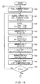
- FIGS. 14 and 15 are flow diagrams showing tire air pressure detecting processing.
- FIG. 16 is a flow diagram showing tread-lift compensation processing.
- processing as in the first embodiment is executed.
- the average wheel speed V AVE corresponding to an average value of respective vehicle wheel speeds V FL , V FR , V RL and V RR is calculated by the average wheel speed calculating portion of the average wheel speed processing portion 3m as in the same manner mentioned above.
- the average wheel speed memorizing portion stores the average wheel speed V AVE calculated at 151 to add memorized average wheel speeds V AVE (N).
- V AVE (N) corresponds to an arrangement of n 0 memorized portions of the average wheel speeds V AVE stored in a position of the memory corresponding to a wheel speed calculation number.
- the average wheel speed memorizing portion re-stores a new average wheel speed V AVE in the position of the memory corresponding to wheel speed calculation number N after the n 0 portions of the average wheel speeds V AVE are stored.
- tread-lift compensation processing is executed by the compensation value feature learning portion, the tread-lift compensating portion and the third wheel speed variation memorizing portion of the tread-lift compensation processing portion 3n.
- the tread-lift compensation processing will now be described with reference to FIG. 16.
- compensation feature learn processing is executed based on the wheel speed variation D and the average wheel speed V AVE as follows.
- An available vehicle speed range in which a vehicle is able to drive is classified into several speed ranges.
- the current average calculated wheel speed V AVE is correlated to one of the several speed ranges to which the average wheel speed V AVE belongs. For example, a vehicle speed range from 85km/h to 155km/h is classified to 14 speed ranges by dividing at every 5km/h. When the current average calculated wheel speed V AVE is 100km/h, it belongs to the fourth speed range. Thus, all currently calculated average wheel speeds V AVE are respectively distinguished.
- the currently calculated wheel speed variation D is also correlated to the same speed range as the average wheel speeds V AVE and added to the summation of the wheel speed variation D. Further, a count of a counter (not shown) is increased in order to recognize data in the speed range in which data of the currently calculated wheel speed variation D is added.
- the tread-lift compensation processing portion 3n determines a number of speed ranges having amount of data larger than a predetermined number (e.g., 15).
- a predetermined number e.g., 15
- each average value of the wheel speed variation D in each speed range having the predetermined number data and a middle value of the speed range i.e., 87.5km/h is a middle value when the speed range is a range from 85km/h to 90km/h
- maximum and minimum values of average values of the wheel speed variation D are compared. When a difference of the maximum and minimum values is below, for example, 0.04, entire average values of the wheel speed variation D of respective speed range are defined at 0.
- the tread-lift compensation processing portion 3n calculates a regression curve (or a regression line) using minimum square calculation methodology if each average value of the wheel speed variation D in each speed range having the predetermined number data and a middle value of the speed range are dotted.
- a regression curve equation expresses a change of the wheel speed variation D, and therefore the compensation feature is obtained based on the regression curve equation. That is, because the wheel speed variation D changes against vehicle speed as with the regression curve equation, the change of the wheel speed variation D caused by the effect of tread-lift is assumed based on the regression curve equation. Therefore, a compensation value for removing the effect of tread-lift from the wheel speed variation D can be learned. Then, a flag is set when calculation of the regression curve (or regression line) is completed and a relational equation of the each vehicle speed and the compensation value is calculated based on the regression curve. Thus, the compensation feature learn processing is completed.
- the tread-lift compensation processing portion 3n determines whether the compensation feature learn processing is completed. Specifically, it is determined based on whether the calculation of the regression curve (or regression line) is completed or not and whether the relational equation of each vehicle speed and the compensation value is calculated. That is, the tread-lift compensation processing portion 3n determines that the compensation feature learn processing is completed when the flag is set.
- the processing advances to 253 to select the predetermined deformation feature for being applied as the tread-lift compensation because the compensation feature learn processing is not completed.
- the deformation feature is defined by, for example, an experiment that investigates a change of a wheel speed variation D against a vehicle speed when tire air pressure is decreased to 1 atm from standard pressure.
- the processing advances to 254 to select the compensation feature obtained at 251 for application as the tread-lift compensation.
- the wheel speed variation D is compensated for based on the predetermined deformation feature or the relational equation of each vehicle speed and the compensation value calculated by the learned compensation feature.
- a wheel speed variation D* is calculated by removing the effect of tread-lift with respect to vehicle speed from the wheel speed variation D.
- wheel speed variation D* is calculated by adding the compensation value to the wheel speed variation D.
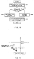
- FIG. 17 a relationship between the wheel speed variation D, D* and a front and rear wheel speed ratio ⁇ is illustrated in FIG. 17.
- white circles ( ⁇ ) indicate the relationship between wheel speed variation D and the front and rear wheel speed ratio ⁇
- black circles ( ⁇ ) indicate the relationship between the wheel speed variation D* and the front and rear wheel speed ratio ⁇ .
- the wheel speed variation D* without the effect of tread-lift can be calculated by compensating for the wheel speed variation D with respect to vehicle speed even if the wheel speed variation D varies due to the effect of tread-lift.
- processing as in the first embodiment is executed.
- the wheel speed variation D* is applied for calculating respective values instead of the wheel speed variation D, and a post-compensation wheel speed variation D' AVE is calculated based on the respective values at 111.
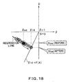
- a relationship between the post-compensation wheel speed variation D' AVE and each value (the value D AVE , the slip variation A, the ideal driven status value ⁇ id, and the average value ⁇ AVE ) for calculating the post-compensation wheel speed variation D' AVE is shown in FIG. 18.
- FIG. 18 shows a relationship between the wheel speed variation D* and the front and rear wheel speed ratio ⁇ when tire air pressure of one of the driven wheels 1c, 1d (e.g., the left rear wheel) decreases.
- white circles ( ⁇ ) indicate n 0 portions of the relationship between the wheel speed variation D* and the front and rear wheel speed ratio ⁇
- black circles ( ⁇ ) indicate a relationship between the average value D AVE of the wheel speed variation D* and the average value ⁇ AVE of the front and rear wheel speed ratio ⁇ .
- a regression line corresponding to a linear function of n 0 portions of the wheel speed variation D and the front and rear wheel speed ratio ⁇ is calculated using minimum square calculation methodology.
- a post-compensation wheel speed variation D' AVE which corresponds to a wheel speed variation D* under an ideal driving status when tire air pressure of at least one of the driven wheels 1c, 1d decreases, is calculated.
- the post-compensation wheel speed variation D' AVE can be calculated without excessive compensation.
- the processing advances to 113 to store the post-compensation wheel speed variation D' AVE calculated now as a reference value D' AVE std and then returns at 100. To the contrary, the processing advances to 160 when the determination at 112 is positive.
- the tire air pressure decrease determination portion 3h determines whether an absolute value
- the processing advances to 162 when a determination is positive.
- the tire air pressure decrease determination portion 3h transmits a warning signal denoting a tire air pressure decrease to the warning device 4.
- the processing returns at 100 when the determination is negative.
- any tire air pressure decrease in any of the respective wheels 1a-1d can be detected.
- the wheel speed variation D* which is assumed when the effect of tread-lift is not generated, is calculated by compensating for the wheel speed variation D with respect to vehicle speed. That is, the wheel speed variation D* is calculated every predetermined short interval. Further, the regression line expressing a relationship between wheel speed variation D* and the front and rear wheel speed ratio ⁇ is calculated based on the wheel speed variation D*, and the post-compensation wheel speed variation D' AVE in which a slip effect of driven wheels 1c, 1d is removed is calculated based on the regression line.
- a plurality of wheel speed variations D within a relatively short interval are needed. Also, because the effect of tread-lift is directly related to vehicle speed, it is effective to compensate for data of relatively short intervals to remove the effect of tread-lift.
- the wheel speed variation D* in which the effect of tread-lift is removed is calculated by compensating for data of the wheel speed variation D within short intervals using vehicle speed as a parameter.
- vehicle speed as a parameter.
- the post-compensation wheel speed variation D' AVE can be calculated without excessive compensation.
- the post-compensation wheel speed variation D' AVE when the tire air pressure of the driven wheel decreases and that when the tire air pressure of the non-driven wheel decreases are identical. Therefore, regardless of which wheels decrease in pressure, the warning pressure remains uniform.
- tire air pressure is detected in a manner different from the fifth embodiment.
- a configuration of a tire air pressure detection device of the sixth embodiment is the same as in the fifth embodiment, but processing executed is differently from the fifth embodiment.
- processing for resetting a wheel speed calculation number N, increasing wheel speed calculation number N, and calculating a relative wheel speed variation D are respectively executed as at 100 through 102 of FIG. 14 in the fifth embodiment.
- the processing then advances to 303 to calculate a front and rear wheel speed ratio ⁇ in the same manner as at 104 in the first embodiment.
- an average wheel speed V AVE is calculated as in the same manner as at 151 of the fifth embodiment.
- the relative wheel speed variation D is stored in a memory corresponding to a speed range with respect to the average wheel speed V AVE calculated at 304.
- the front and rear wheel speed ratio ⁇ is stored in a memory location corresponding to the speed range with respect to the average wheel speed V AVE calculated at 304.
- the speed range with respect to the average wheel speed V AVE is as defined by the compensation feature learn processing (see at 251 in FIG. 16) of the tread-lift compensation processing in the fifth embodiment. That is, memory locations are equipped so that one location corresponding to the speed range of the average wheel speed V AVE stores the relative wheel speed variation D and the front and rear wheel speed ratio ⁇ .
- the processing advances to 307 to execute processing for removing old data in each memory location.
- a counter is equipped with respect to each data memory location in each speed range. Each counter is incremented when data is stored in any one of the memory locations of any speed range even if the data is not stored in the memory locations associated with the other counters. Therefore, each interval in which data is stored in one of the memory locations is recognized.
- the data is then deleted when the counter corresponding to the data has counted for a predetermined time (e.g., 10 minutes). Accordingly, when tire air pressures begin to decrease, the regression line is not calculated using old data such as data calculated prior to a decrease in tire air pressure.
- the tread-lift compensation portion 3n determines whether a number of speed ranges having a predetermined data number N 0 is at least K. The processing advances to 309 when the number of speed ranges is at least K, while returning at 301 when the number of speed ranges is less than K.
- a slip variation A an average value D AVE of the wheel speed variation D, an average value ⁇ AVE of the front and rear wheel speed ratio ⁇ , an ideal driving status value ⁇ id, and a post-compensation wheel speed variation D' AVE are calculated for every speed range having the predetermined data number N 0 in parallel.
- This processing is executed in the same manner as at 107 through 111 of the fifth embodiment. However, in the present embodiment, since the tread-lift compensation mentioned in the fifth embodiment is not executed, the processing is executed using the wheel speed variation D calculated at 302.
- FIG. 21 shows relationships between a slip variation A and the post-compensation wheel speed variation D' AVE in each speed range according to a sixth embodiment. The processing at 314 will now be described with reference to FIG. 21.
- speed ranges of 110km/h, 140km/h, 160km/h and 180km/h are the ranges having the predetermined data number N 0
- respective relationships between the wheel speed variation D and the front and rear wheel speed ratio ⁇ are illustrated in (a) of FIG. 21, and therefore the slip variation A of each speed range is calculated.
- the post-compensation wheel speed variation D' AVE is calculated based on the slip variation A of each speed range.
- the wheel speed variation D is not compensated for against tread-lift
- the post-compensation wheel speed variation D' AVE is calculated without the effect of tread-lift at every speed range because the effect of tread-lift of the wheel speed variation D is approximately the same at every speed range.
- a relationship between the post-compensation wheel speed variation D' AVE and the speed range is shown with white circles ( ⁇ ) in (b) of FIG. 21. Therefore, the regression curve is calculated using minimum square calculation methodology based on the post-compensation wheel speed variation D' AVE .
- Black circles ( ⁇ ) indicate a post-compensation wheel speed variation D' AVE with a vehicle speed Vbase (e.g., 80km/h) on which an effect of tread-lift can be negligible.
- the post-compensation wheel speed variation D' AVE is compensated for in the same manner as at 251 shown in FIG. 16 of the fifth embodiment to calculate the reference value D''' AVE std with a vehicle speed Vbase on which an effect of tread-lift can be negligible.
- the processing then advances to 315.
- calculating a pressure difference determination value ⁇ D''' AVE comparing the pressure difference determination value ⁇ D''' AVE and a threshold value ⁇ D'''sh, and transmitting a warning signal to a warning device 4 are respectively executed as the same processing as at 160 through 162 in the fifth embodiment.
- the tire air pressure decrease is detected by determining whether the post-compensation wheel speed variation D' AVE exceeds the warning threshold.
- the compensation equation is an example.
- Other compensation equations can alternatively be adapted for compensating for the difference determination value.
- appropriate compensation equations are different with respect to tire air pressure decrease depending on regression line location, different equations can be adapted with respect to the tire air pressure decrease depending on the regression line location.
- the difference determination value ⁇ D' AVE is applied for determining tire air pressure decrease.
- other values such as the wheel speed variation D are applied for determining tire air pressure decrease.
- respective tire air pressure detection devices are adapted for use in a rear wheel drive vehicle, but can alternatively be adapted for use in a front wheel drive vehicle.
- an ideal driving status value ⁇ id is at least 1 with respect to the tire air pressure decrease of a driven wheel.
- the wheel speed variation D is calculated as a rotational status value using equation (1).
- the rotational status value is a value expressing a relationship of respective wheels 1a-1d so as to cancel a wheel speed variation between left and right wheels generated due to vehicle turns.
- a slip variation A a slope of a regression line
- the slip variation A is approximately zero. Therefore, upon removing the compensation processing when the slip variation A is small, it is possible to remove data when compensation processing is not needed even if tire air pressure of one of the rear wheels decreases and when tire air pressure of one of the front wheels decreases.
- are calculated based on n 0 portions of the wheel speed variation D and the front and rear wheel speed ratio ⁇ when the number of calculations N reaches n 0 .
- tire air pressure decrease is not detected until all n 0 portions of data are renewed. Accordingly, upon calculating a moving average, tire air pressure decrease can be detected even if all n 0 portions of data are not renewed.
- the moving average renews the oldest data of the wheel speed variation D and the front and rear wheel speed ratio ⁇ stored in the wheel speed variation memorizing portion and the front and rear wheel speed ratio memorizing portion. Then, the average value D AVE and the average value ⁇ AVE are periodically calculated when at least one of the wheel speed variation D and at least one of the front and rear wheel speed ratio ⁇ are renewed.
- the above-mentioned regression line accuracy evaluating processing can alternatively be adapted for other tire air pressure detection devices that use a compensation methodology disclosed by the related art invention.
Landscapes
- Engineering & Computer Science (AREA)
- Mechanical Engineering (AREA)
- Measuring Fluid Pressure (AREA)
Applications Claiming Priority (7)
| Application Number | Priority Date | Filing Date | Title |
|---|---|---|---|
| JP2001032477 | 2001-02-08 | ||
| JP2001032478A JP3772677B2 (ja) | 2001-02-08 | 2001-02-08 | タイヤ空気圧検出装置 |
| JP2001032477A JP2002234318A (ja) | 2001-02-08 | 2001-02-08 | タイヤ空気圧検出装置 |
| JP2001032478 | 2001-02-08 | ||
| JP2001032482A JP2002234323A (ja) | 2001-02-08 | 2001-02-08 | タイヤ空気圧検出装置 |
| JP2001032482 | 2001-02-08 | ||
| PCT/JP2002/000957 WO2002062597A1 (fr) | 2001-02-08 | 2002-02-06 | Detecteur de pression pneumatique de pneu |
Publications (2)
| Publication Number | Publication Date |
|---|---|
| EP1366932A1 true EP1366932A1 (fr) | 2003-12-03 |
| EP1366932A4 EP1366932A4 (fr) | 2005-03-16 |
Family
ID=27345939
Family Applications (1)
| Application Number | Title | Priority Date | Filing Date |
|---|---|---|---|
| EP02711326A Withdrawn EP1366932A4 (fr) | 2001-02-08 | 2002-02-06 | Detecteur de pression pneumatique de pneu |
Country Status (6)
| Country | Link |
|---|---|
| US (1) | US6768418B2 (fr) |
| EP (1) | EP1366932A4 (fr) |
| KR (1) | KR20040011459A (fr) |
| CN (1) | CN1491166A (fr) |
| CA (1) | CA2438100A1 (fr) |
| WO (1) | WO2002062597A1 (fr) |
Families Citing this family (16)
| Publication number | Priority date | Publication date | Assignee | Title |
|---|---|---|---|---|
| US8266465B2 (en) | 2000-07-26 | 2012-09-11 | Bridgestone Americas Tire Operation, LLC | System for conserving battery life in a battery operated device |
| US7161476B2 (en) | 2000-07-26 | 2007-01-09 | Bridgestone Firestone North American Tire, Llc | Electronic tire management system |
| US7634341B2 (en) * | 2001-03-07 | 2009-12-15 | 1138037 Ontario Ltd. (“Alirt”) | Detecting device and method of using same |
| US7081693B2 (en) * | 2002-03-07 | 2006-07-25 | Microstrain, Inc. | Energy harvesting for wireless sensor operation and data transmission |
| CN1297417C (zh) * | 2003-08-20 | 2007-01-31 | 重庆三信电子有限公司 | 汽车轮胎压力监测系统 |
| JP4175306B2 (ja) * | 2003-09-18 | 2008-11-05 | 株式会社デンソー | タイヤ空気圧監視システム |
| EP1547828B1 (fr) * | 2003-11-25 | 2010-10-20 | Sumitomo Rubber Industries Limited | Procédé et appareil de détection d'une baisse de pression dans un pneumatique, et programme pour juger cette baisse de pression |
| US7132939B2 (en) * | 2004-07-07 | 2006-11-07 | Michelin Recherche Et Technique S.A. | Integrated self-powered tire revolution counter |
| JP4490342B2 (ja) * | 2005-07-08 | 2010-06-23 | 住友ゴム工業株式会社 | タイヤ空気圧低下検出方法及び装置、並びにタイヤ減圧判定のプログラム |
| CN100466004C (zh) * | 2006-04-03 | 2009-03-04 | 环隆电气股份有限公司 | 无线传输轮胎检测信号的方法 |
| JP2010521365A (ja) * | 2007-03-16 | 2010-06-24 | ニラ・ダイナミクス・エイビイ | タイヤ空気圧間接監視における較正 |
| JP2008249523A (ja) * | 2007-03-30 | 2008-10-16 | Sumitomo Rubber Ind Ltd | タイヤ空気圧低下異常警報方法および装置ならびにプログラム |
| US8350688B2 (en) * | 2010-03-01 | 2013-01-08 | International Truck Intellectual Property Company, Llc | System and method for indirect indication of tire pressure loss |
| US9141669B2 (en) * | 2013-01-22 | 2015-09-22 | Go Daddy Operating Company, LLC | Configuring an origin server content delivery using a pulled data list |
| CN109203876A (zh) * | 2017-07-07 | 2019-01-15 | 杭州中策车空间汽车服务有限公司 | 集成轮胎组网的风控处理方法和系统 |
| FR3082081B1 (fr) * | 2018-05-31 | 2020-06-05 | Continental Automotive France | Procede de reconfiguration d’un dispositif de controle d’un pneumatique de vehicule automobile |
Family Cites Families (18)
| Publication number | Priority date | Publication date | Assignee | Title |
|---|---|---|---|---|
| JP3135437B2 (ja) * | 1993-11-04 | 2001-02-13 | 住友電気工業株式会社 | タイヤ空気圧低下判定方法およびこの方法を用いたタイヤ空気圧低下検出装置 |
| JP3509330B2 (ja) * | 1995-10-11 | 2004-03-22 | 本田技研工業株式会社 | 車両の車輪減圧判定装置 |
| EP0786361B1 (fr) | 1996-01-26 | 2002-01-02 | COMPAGNIE GENERALE DES ETABLISSEMENTS MICHELIN-MICHELIN & CIE | Procédé d'exploitation des signaux dans un système de surveillance des pneumatiques d'un véhicule en roulage |
| JP3119809B2 (ja) * | 1996-01-26 | 2000-12-25 | 住友電気工業株式会社 | タイヤ空気圧低下検出方法および装置 |
| GB9602443D0 (en) * | 1996-02-07 | 1996-04-03 | Sumitomo Rubber Ind | Method of detecting a deflated tyre on a vehicle |
| JP3158038B2 (ja) * | 1996-03-14 | 2001-04-23 | 住友電気工業株式会社 | タイヤ空気圧低下検出装置 |
| JP3129671B2 (ja) * | 1996-04-15 | 2001-01-31 | 住友ゴム工業株式会社 | タイヤの空気圧低下検出方法およびその装置 |
| JP3167276B2 (ja) * | 1996-09-04 | 2001-05-21 | 住友電気工業株式会社 | タイヤ空気圧低下検出方法および装置 |
| JP3333691B2 (ja) | 1996-09-25 | 2002-10-15 | 株式会社日本自動車部品総合研究所 | タイヤ空気圧検知装置 |
| JP3333698B2 (ja) | 1996-10-25 | 2002-10-15 | 株式会社日本自動車部品総合研究所 | タイヤ空気圧検知装置 |
| JP3333693B2 (ja) * | 1996-09-26 | 2002-10-15 | 株式会社日本自動車部品総合研究所 | タイヤ空気圧検知装置 |
| EP0832768B1 (fr) | 1996-09-26 | 2002-08-28 | Denso Corporation | Appareil de détection de la pression de pneumatiques |
| JP3300620B2 (ja) | 1996-12-17 | 2002-07-08 | トヨタ自動車株式会社 | タイヤ空気圧推定装置 |
| EP0850816A3 (fr) * | 1996-12-25 | 1999-04-14 | Kabushiki Kaisha Toyota Chuo Kenkyusho | Appareil de diagnose d'un système dynamique, dispositif d'estimation de la pression de freinage, régulateur du frein anti-blocage, et régulateur de la pression de freinage |
| JPH10193933A (ja) | 1997-01-10 | 1998-07-28 | Toyota Motor Corp | タイヤ空気圧推定装置 |
| JP3695884B2 (ja) | 1997-03-18 | 2005-09-14 | トヨタ自動車株式会社 | タイヤ空気圧推定装置 |
| JP3811260B2 (ja) | 1997-06-16 | 2006-08-16 | トヨタ自動車株式会社 | タイヤ空気圧判定装置及びその方法 |
| US6137400A (en) * | 1997-08-22 | 2000-10-24 | Sumitomo Rubber Industries, Ltd. | Apparatus and method for detecting decrease in tire air-pressure |
-
2002
- 2002-02-06 CN CNA028047044A patent/CN1491166A/zh active Pending
- 2002-02-06 CA CA002438100A patent/CA2438100A1/fr not_active Abandoned
- 2002-02-06 KR KR10-2003-7010237A patent/KR20040011459A/ko not_active Ceased
- 2002-02-06 WO PCT/JP2002/000957 patent/WO2002062597A1/fr not_active Ceased
- 2002-02-06 EP EP02711326A patent/EP1366932A4/fr not_active Withdrawn
- 2002-10-04 US US10/264,282 patent/US6768418B2/en not_active Expired - Fee Related
Non-Patent Citations (1)
| Title |
|---|
| See references of WO02062597A1 * |
Also Published As
| Publication number | Publication date |
|---|---|
| CN1491166A (zh) | 2004-04-21 |
| WO2002062597A1 (fr) | 2002-08-15 |
| US20030076223A1 (en) | 2003-04-24 |
| CA2438100A1 (fr) | 2002-08-15 |
| EP1366932A4 (fr) | 2005-03-16 |
| US6768418B2 (en) | 2004-07-27 |
| KR20040011459A (ko) | 2004-02-05 |
Similar Documents
| Publication | Publication Date | Title |
|---|---|---|
| EP1366932A1 (fr) | Detecteur de pression pneumatique de pneu | |
| US6940399B2 (en) | Tire air pressure detection device for detecting air pressure based on vehicle speed signal | |
| US6118369A (en) | Tire diagnostic system | |
| US6002327A (en) | Low tire warning system with axle torque signal | |
| EP0855597B1 (fr) | Dispositif pour déterminer des facteurs initiaux de correction pour corriger des mesures de la vitesse angulaire des roues d'un véhicule | |
| US20040260436A1 (en) | Tire pressure monitoring system | |
| US20160033367A1 (en) | System and method for determining tire wear | |
| EP0897816A2 (fr) | Appareil et procédé d'alarme de réduction de pression d'un pneumatique | |
| JP4256797B2 (ja) | タイヤ空気圧低下警報方法および装置、ならびにタイヤ減圧判定のプログラム | |
| EP0832767B1 (fr) | Méthode et dispositif de détection de perte de pression d'un pneumatique | |
| EP0861743B1 (fr) | Dispositif de calcul de facteur initial de correction pour corriger la vitesse de rotation de la roue | |
| EP1527909A2 (fr) | Procédé et appareil de détection d'une baisse de pression dans un pneumatique | |
| KR19980076549A (ko) | 타이어의 공기압 저하 검출방법 및 장치 | |
| JP2003211925A (ja) | タイヤ空気圧低下警報方法および装置、ならびにタイヤ減圧判定のプログラム | |
| EP1352765A2 (fr) | Procédé et appareil concernant la détection d'une baisse de pression dans un pneumatique, et programme pour juger la décompression du pneumatique | |
| US6956471B2 (en) | Hybrid tire inflation monitor | |
| US6407661B2 (en) | Apparatus and method for alarming decrease in tire air-pressure | |
| JP2005088726A (ja) | タイヤ空気圧警報装置、この装置によって監視されるタイヤ、およびタイヤの特性値の管理方法 | |
| US6388568B1 (en) | Apparatus and method for alarming decrease in tire air-pressure | |
| EP1371507B1 (fr) | Procédé et appareil de détection d'une baisse de pression dans un pneumatique, et pour juger la décompression du pneumatique | |
| JP5126048B2 (ja) | タイヤ空気圧監視装置 | |
| JP3167278B2 (ja) | タイヤ空気圧低下検出方法および装置 | |
| JP3957656B2 (ja) | タイヤ空気圧低下検出方法および装置、ならびにタイヤ減圧判定のプログラム | |
| JP2002234323A (ja) | タイヤ空気圧検出装置 | |
| JP3396522B2 (ja) | タイヤ空気圧低下判定方法およびタイヤ空気圧低下検出装置 |
Legal Events
| Date | Code | Title | Description |
|---|---|---|---|
| PUAI | Public reference made under article 153(3) epc to a published international application that has entered the european phase |
Free format text: ORIGINAL CODE: 0009012 |
|
| 17P | Request for examination filed |
Effective date: 20030908 |
|
| AK | Designated contracting states |
Kind code of ref document: A1 Designated state(s): DE FR GB |
|
| RIN1 | Information on inventor provided before grant (corrected) |
Inventor name: NAITO, TOSHIHARUC/O DENSO CORPORATION Inventor name: OHASHI, HIDEKITOYOTA JIDOSHA KABUSHIKI KAISHA Inventor name: TABATA, MASAAKITOYOTA JIDOSHA KABUSHIKI KAISHA Inventor name: TAGUCHI, TAKEYASUC/O DENSO CORPORATION Inventor name: MORI, YUKIOC/O AISIN SEIKI KABUSHIKI KAISHA Inventor name: TOMINAGA, MOTONORIC/O NIPPON SOKEN INC. |
|
| A4 | Supplementary search report drawn up and despatched |
Effective date: 20050201 |
|
| RAP1 | Party data changed (applicant data changed or rights of an application transferred) |
Owner name: TOYOTA JIDOSHA KABUSHIKI KAISHA Owner name: AISIN SEIKI KABUSHIKI KAISHA Owner name: DENSO CORPORATION |
|
| RAP1 | Party data changed (applicant data changed or rights of an application transferred) |
Owner name: AISIN SEIKI KABUSHIKI KAISHA Owner name: TOYOTA JIDOSHA KABUSHIKI KAISHA Owner name: DENSO CORPORATION |
|
| STAA | Information on the status of an ep patent application or granted ep patent |
Free format text: STATUS: THE APPLICATION IS DEEMED TO BE WITHDRAWN |
|
| 18D | Application deemed to be withdrawn |
Effective date: 20060419 |