EP1366971A2 - Sattelzugmaschine - Google Patents
Sattelzugmaschine Download PDFInfo
- Publication number
- EP1366971A2 EP1366971A2 EP03009095A EP03009095A EP1366971A2 EP 1366971 A2 EP1366971 A2 EP 1366971A2 EP 03009095 A EP03009095 A EP 03009095A EP 03009095 A EP03009095 A EP 03009095A EP 1366971 A2 EP1366971 A2 EP 1366971A2
- Authority
- EP
- European Patent Office
- Prior art keywords
- tractor unit
- semi
- trailer
- lifting device
- tractor
- Prior art date
- Legal status (The legal status is an assumption and is not a legal conclusion. Google has not performed a legal analysis and makes no representation as to the accuracy of the status listed.)
- Granted
Links
- 230000005540 biological transmission Effects 0.000 claims abstract description 46
- 238000010168 coupling process Methods 0.000 claims description 21
- 230000008878 coupling Effects 0.000 claims description 17
- 238000005859 coupling reaction Methods 0.000 claims description 17
- 230000001360 synchronised effect Effects 0.000 claims description 3
- 238000005096 rolling process Methods 0.000 description 5
- 238000012546 transfer Methods 0.000 description 4
- 238000011161 development Methods 0.000 description 3
- 238000012549 training Methods 0.000 description 3
- 230000009471 action Effects 0.000 description 1
- 238000004873 anchoring Methods 0.000 description 1
- 230000003466 anti-cipated effect Effects 0.000 description 1
- 238000013459 approach Methods 0.000 description 1
- 230000000694 effects Effects 0.000 description 1
- 239000000463 material Substances 0.000 description 1
- 230000007246 mechanism Effects 0.000 description 1
- 239000002184 metal Substances 0.000 description 1
- 210000003205 muscle Anatomy 0.000 description 1
Images


Classifications
-
- B—PERFORMING OPERATIONS; TRANSPORTING
- B62—LAND VEHICLES FOR TRAVELLING OTHERWISE THAN ON RAILS
- B62D—MOTOR VEHICLES; TRAILERS
- B62D53/00—Tractor-trailer combinations; Road trains
- B62D53/04—Tractor-trailer combinations; Road trains comprising a vehicle carrying an essential part of the other vehicle's load by having supporting means for the front or rear part of the other vehicle
- B62D53/08—Fifth wheel traction couplings
- B62D53/0807—Fifth wheel traction couplings adjustable coupling saddles mounted on sub-frames; Mounting plates therefor
- B62D53/0821—Lifting saddles, i.e. to lift the trailer front
Definitions
- the invention relates to a tractor unit with a fifth wheel plate Coupling a semi-trailer.
- Tractor units for transporting semitrailers are, for example known from DE 197 52 108 A1.
- a tractor unit consists of Essentially consisting of a cab, a vehicle drive, steerable and rigidly suspended wheels and a coupling device in the area a fifth wheel plate, which is located in the rear area of the tractor unit located.
- a semi-trailer essentially consists of one Loading area in which the payload is stowed, one Coupling device in the front area of the semi-trailer Underside and several, mostly rigidly suspended wheels in the rear Area of the semi-trailer.
- the semi-trailer When coupled, the semi-trailer lies on the fifth wheel, wherein the coupling device and the coupling device a Attach the semi-trailer to the saddle plate. I'm not coupled state, the front part of a semi-trailer must be supported become. This is usually done by integrated on the semi-trailer Support legs.
- Auto trestle consisting of one U-shaped support standing on its legs, which Attachment options for both the semi-trailer, which on the Bridge of the U-shaped beam rests, as well as for floor anchoring offers at the ends of the legs.
- Auto trestles are mostly used for Maritime transport used on ships to carry out the jam work, in particular the Lechen, accelerate and the semi-trailer against slipping, around rough seas.
- the support legs of the semi-trailer are used manually cranked up. This requires a lot of time and muscle strength.
- external lifting devices such as a crane. On Coupling process is very expensive and requires that Availability of the external lifting device. In both cases, external energy be used in the coupling process. After lifting the Semi-trailer drives the tractor unit under the semi-trailer and thus couples the semi-trailer.
- tractor unit and / or semi-trailers have on their rear or front End over an inclined surface, causing a lifting of the semi-trailer during the run-down by wedge action.
- a minimum speed of the tractor unit required, which is a considerable material stress, especially due to plastic deformation as well as endangering cargo and personnel.
- the present invention has for its object to couple a Semitrailer to a tractor unit easier and safer to be able to perform.
- This task is accomplished by a tractor unit at the beginning presented type solved in that at the back of the Tractor unit a lifting device for lifting the semi-trailer is appropriate. It becomes a simple and safe coupling and uncoupling made possible by semi-trailers. One in the tractor unit Driver can control all necessary measures.
- the Tractor unit is due to the additional lifting device for the Handling a large number of semi-trailers, especially those with a small number Underride height, suitable.
- a conventional tractor unit is light with a lifting device can be retrofitted according to the invention, so that the invention is inexpensive existing tractor units can be used.
- the lifting device of the tractor unit according to the invention can for example mechanically, electromechanically, pneumatically or work hydraulically.
- An embodiment of the invention is particularly advantageous Tractor unit in which the lifting device is an upper support device with a movably mounted upper transmission link for contact with has the underside of the semi-trailer.
- the upper link first grips under the lower edge of the front end of the semi-trailer and is then moved up to raise the semi-trailer. in the Then the tractor unit drives under the semi-trailer, the semi-trailer must remain raised, preferably also while maintaining its vertical position. Slides to it the upper transmission link on the underside of the semi-trailer according to the speed of the tractor unit.
- the upper transmission link can therefore the vertical and horizontal position of the semi-trailer are easily maintained when driving under.
- the lifting device has a lower one Support device with a movably mounted lower transmission link to contact the road.
- the raised state of the Semitrailer is thus at least part of the drawbar load on the Lifting device via the lower support device or the lower one Transfer link to the ground (the road).
- a torque on the Tractor unit which can cause it to tip over, reduced and the attachment of the lifting device to the tractor unit mechanically relieved.
- the torque arises as a result of Force behind the rear axle of the tractor unit.
- the lower transmission link slides on the roadway along.
- a further development according to the invention is particularly advantageous, in which the upper and / or the lower transmission link by a roller or a wheel are formed.
- the top Transmission link as a roller or wheel is sliding on the underside of the Semi-trailer easily possible while driving under. Just as easy it is possible to slide the lower transmission link on the road during the underride.
- the sliding is here by rolling causes.
- the upper transmission link can also have several Include rollers or wheels; the lower transmission link can do the same also include multiple roles or wheels. Roles are particularly preferred or wheels with a high coefficient of friction.
- rollers or wheels as transmission links Sliding surfaces, in particular convex shaped metal surfaces, the are cheaper than rollers or wheels.
- the movement of the Transmission links of the upper and lower support devices synchronized.
- a synchronization of 1: -1 is selected so that the rolling distance of the upper transmission link is the same Rolling distance of the lower transmission link.
- the easiest way is through Wheels with the same radius on the upper and lower transmission link realizable. This will transfer horizontal forces to the Avoided semi-trailers when driving under them, i.e. the semi-trailer becomes not parallel to the lane and in the direction of movement of the backwards moving tractor unit moved. So it effectively becomes one Braking effect on the semi-trailer achieved when driving under.
- the Synchronization of the wheels with road contact and trailer contact can in particular mechanically or hydraulically.
- the lower one Support device is positioned further back on the tractor unit than the upper support. This additionally secures the tractor unit against tipping in the raised state or when lifting the Semi-trailer if the load attack behind the rear axle (as a potential Axis of rotation / tilting axis) of the tractor unit.
- the lifting device is designed to Reach under semi-trailers that are mounted on an auto trestle and the bottom edge of the auto trestle at least at the level of the Raise the saddle plate.
- the auto trestle reduces the underride height of the Unit of auto-trestle and semi-trailer when coupling to one Tractor Unit.
- the tractor is universally applicable and especially for the Envelope from auto-trestles-equipped megatrailers like the one in Seaports are common. Conventional tractors for megatrailers are unable to auto-trestle-equipped mega trailers handle, in particular to drive under.
- FIG. 1 shows an embodiment of a tractor unit 1 according to the invention which is suitable for coupling semitrailers whose underride height is less than the height of a fifth wheel 2 of the tractor unit 1 .
- the tractor unit 1 For saddling up, the tractor unit 1 is brought into line with the parked semitrailer (not shown in FIG. 1).
- the lifting device 3 is mounted so deep on the tractor unit 1 that all common types of semitrailers, in particular megatrailers, can be easily accessed.
- a lower support device 4 is then made ready for operation by moving a lower transmission member 5 down and thus bringing it into contact with a roadway 6 . Its horizontal position is then fixed.
- the lower transmission member 5 is designed as a pair of wheels. Put simply, the rear support wheels are extended.
- An upper support device 7 is then brought into position by moving an upper transmission member 8 upwards until it touches a support surface in the front region of the semi-trailer from below. With a further stroke of the upper transmission member 8, the semi-trailer (or its contact surface in the front area) is raised to the height of the saddle plate 2. This horizontal position of the upper transmission member 8 is also fixed.
- the upper transmission member 8 is designed as a pair of wheels. Roughly simplified, the front support wheels are extended and the semi-trailer is raised.
- the wheels of the upper transmission member 8 are rolled in the direction of arrow 9 , that is counterclockwise, on the underside of the semi-trailer.
- the wheels of the lower transmission member 5 are rolled in the direction of arrow 10 , ie clockwise, on the surface of the road 6.
- the wheels of the upper transmission element 8 and the lower transmission element 5 have identical diameters and are synchronized according to the invention in such a way that their angular velocities are identical in terms of amount, but are set with a different sign.
- the kingpin of the semi-trailer can be in its horizontal Position on tractor unit 1 are secured.
- the upper support 7 and the lower Move support device 4 back to the basic state, i.e. the Training wheels are retracted.
- the top Support device 7 carries the full load transfer to the saddle plate 2. Then the tractor unit 1 including the semi-trailer is ready to drive.
- a possible coupling mechanism is first between Semi-trailer and tractor unit 1 loosened (i.e. the kingpin is unlocked) and the lower transmission link 5 (the rear support wheels) is extended. Then the upper link 8 (i.e. the front support wheels) extended to the height of the saddle plate 2 The tractor unit 1 then moves forward a short distance, until the semitrailer only rests on the lifting device 3. After that the upper transmission member 8 is pulled in (retracting the front support wheels), the semi-trailer on integrated supports of the Semitrailer (see Figure 3) is discontinued, and then that Pulling in the lower transmission links 5. This is the Tractor unit 1 unsaddled and can be used again be moved.
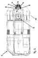
- FIG. 2 shows a schematic view of the tractor unit 1 in plan view.
- the lifting device 3 comprises an upper support device 7, the upper transmission member 8, which can be moved horizontally, is designed as a pair of two wheels.
- the lower support device 4 has a lower transmission member 5 which can be moved horizontally and is also designed as a pair of wheels.
- all the wheels of the lifting device 3 have the same diameter and have a high coefficient of friction for good grip along their rolling path.
- FIGS. 3a to 3e show the sequence of a coupling process of a semitrailer 12 with a tractor unit 1 according to the invention. Only one front part of the semitrailer 12 is shown, and only one rear part of the tractor unit 1 is shown in FIGS. 3a to 3e.
- the tractor unit 1 is oriented in the initial state such that the lifting device 3, which is in the retracted state, is towered over by the semi-trailer 12.
- the clearance height 13 of the semi-trailer 12 is less than the height of the saddle plate 2.
- the semi-trailer is supported by a support structure 14 .
- the semitrailer 12 also has a kingpin 16 in the area of a support surface 15 .
- the upper transmission member 8 of the upper support device 7 is extended.
- a further stroke causes the semi-trailer 12 to be raised in its front region.
- the desired stroke is achieved when the support surface 15 is at the same height as the saddle plate 2. This position is shown in Figure 3c .
Landscapes
- Engineering & Computer Science (AREA)
- Chemical & Material Sciences (AREA)
- Combustion & Propulsion (AREA)
- Transportation (AREA)
- Mechanical Engineering (AREA)
- Vehicle Cleaning, Maintenance, Repair, Refitting, And Outriggers (AREA)
- High-Pressure Fuel Injection Pump Control (AREA)
- Agricultural Machines (AREA)
Abstract
Description
- Die Sattelzugmaschine fährt an den Sattelauflieger heran, so dass die Zugmaschine und Sattelauflieger etwa in einer Linie stehen und die Rückseite der Sattelzugmaschine an die Vorderseite des Sattelaufliegers grenzt. In dieser Position überragt der Sattelauflieger die Hubeinrichtung der Sattelzugmaschine, wobei die Hubeinrichtung tiefer angebracht ist als die Unterfahrhöhe des Sattelaufliegers beträgt (Orientieren der Sattelzugmaschine);
- der Sattelauflieger wird von der Hubeinrichtung der Sattelzugmaschine angehoben, so dass die Unterkante des Sattelaufliegers auf die Höhe der Sattelplatte der Zugmaschine gelangt (Anheben des Sattelaufliegers);
- im angehobenen Zustand unterfährt die Sattelzugmaschine den Sattelauflieger, d.h. sie fährt rückwärts; dabei wird die Hubeinrichtung entlang der Unterseite des Sattelaufliegers verschoben (Unterfahren); nachdem der Königszapfen der Ankuppelvorrichtung des Sattelaufliegers in seine Endposition in der Kupplungsvorrichtung im Bereich der Sattelplatte der Sattelzugmaschine gelangt ist, wird der Königszapfen gesichert (Ankuppeln); danach wird die Hubeinrichtung wieder eingefahren.
- Fig. 1
- eine erfindungsgemäße Sattelzugmaschine mit einer Hubeinrichtung in schematischer Seitenansicht;
- Fig. 2
- eine erfindungsgemäße Sattelzugmaschine mit einer Hubeinrichtung in schematischer Draufsicht;
- Fig. 3a-3e
- verschiedene Stadien beim Ankuppeln eines Sattelaufliegers mit einer erfindungsgemäßen Sattelzugmaschine in schematischer Seitenansicht.
- 1
- Sattelzugmaschine
- 2
- Sattelplatte
- 3
- Hubeinrichtung
- 4
- untere Stützeinrichtung
- 5
- unteres Übertragungsglied
- 6
- Fahrbahn
- 7
- obere Stützeinrichtung
- 8
- oberes Übertragungsglied
- 9
- Abrollrichtung des oberen Übertragungsgliedes beim Unterfahren
- 10
- Abrollrichtung des unteren Übertragungsgliedes beim Unterfahren
- 11
- Hinterachse
- 12
- Sattelauflieger
- 13
- Unterfahrhöhe
- 14
- Stützkonstruktion
- 15
- Auflagefläche
- 16
- Königszapfen
Claims (7)
- Sattelzugmaschine (1) mit einer Sattelplatte (2) zum Ankuppeln eines Sattelaufliegers (12), dadurch gekennzeichnet, dass an der Rückseite der Sattelzugmaschine (1) eine Hubeinrichtung (3) zum Anheben des Sattelaufliegers (12) angebracht ist.
- Sattelzugmaschine (1) nach Anspruch 1, dadurch gekennzeichnet, dass die Hubeinrichtung (3) eine obere Stützeinrichtung (7) mit einem beweglich gelagerten oberen Übertragungsglied (8) zum Kontakt mit der Unterseite (15) des Sattelaufliegers (12) aufweist.
- Sattelzugmaschine (1) nach Anspruch 1 oder 2, dadurch gekennzeichnet, dass die Hubeinrichtung (3) eine untere Stützeinrichtung (4) mit einem beweglich gelagerten unteren Übertragungsglied (5) zum Kontakt mit der Fahrbahn (6) aufweist.
- Sattelzugmaschine (1) nach Anspruch 2 oder 3, dadurch gekennzeichnet, dass das obere und/oder das untere Übertragungsglied (8, 5) durch eine Rolle oder ein Rad ausgebildet sind.
- Sattelzugmaschine (1) nach Anspruch 2 und 3, dadurch gekennzeichnet, dass die Bewegung der Übertragungsglieder (8, 5) der oberen und der unteren Stützeinrichtung (7, 4) synchronisiert ist.
- Sattelzugmaschine (1) nach einem der Ansprüche 3 bis 5, dadurch gekennzeichnet, dass die untere Stützeinrichtung (4) weiter hinten an der Sattelzugmaschine (1) positioniert ist als die obere Stützeinrichtung (7).
- Sattelzugmaschine (1) nach einem der Ansprüche 3 bis 6, dadurch gekennzeichnet, dass die Hubeinrichtung (3) dazu ausgestaltet ist, Sattelauflieger (12), die auf einem Auto-Trestle montiert sind, zu untergreifen und die Unterkante des Auto-Trestles mindestens auf die Höhe der Sattelplatte (2) anzuheben.
Applications Claiming Priority (2)
| Application Number | Priority Date | Filing Date | Title |
|---|---|---|---|
| DE10223612A DE10223612C1 (de) | 2002-05-27 | 2002-05-27 | Sattelzugmaschine |
| DE10223612 | 2002-05-27 |
Publications (3)
| Publication Number | Publication Date |
|---|---|
| EP1366971A2 true EP1366971A2 (de) | 2003-12-03 |
| EP1366971A3 EP1366971A3 (de) | 2004-01-28 |
| EP1366971B1 EP1366971B1 (de) | 2006-07-26 |
Family
ID=7714586
Family Applications (1)
| Application Number | Title | Priority Date | Filing Date |
|---|---|---|---|
| EP03009095A Expired - Lifetime EP1366971B1 (de) | 2002-05-27 | 2003-04-19 | Sattelzugmaschine |
Country Status (3)
| Country | Link |
|---|---|
| EP (1) | EP1366971B1 (de) |
| AT (1) | ATE334036T1 (de) |
| DE (2) | DE10223612C1 (de) |
Families Citing this family (3)
| Publication number | Priority date | Publication date | Assignee | Title |
|---|---|---|---|---|
| SE529059C2 (sv) * | 2005-11-07 | 2007-04-17 | Volvo Lastvagnar Ab | Ett dragdon avsedd för tillkoppling av en påhängsvagn |
| GB2437947B (en) * | 2006-05-10 | 2010-04-28 | Fontaine Int Europe Ltd | Lead on ramp assembly associated with trailer coupling |
| FR3109923A1 (fr) | 2020-05-06 | 2021-11-12 | Sp-Trailer | Véhicule automoteur pour la manutention notamment de semi-remorques |
Citations (1)
| Publication number | Priority date | Publication date | Assignee | Title |
|---|---|---|---|---|
| DE19752108A1 (de) | 1997-11-25 | 1999-05-27 | Man Nutzfahrzeuge Ag | Verfahren zur Erhöhung des Freiganges zwischen einer Sattelzugmaschine und einem Auflieger |
Family Cites Families (6)
| Publication number | Priority date | Publication date | Assignee | Title |
|---|---|---|---|---|
| GB1119183A (en) * | 1965-05-26 | 1968-07-10 | Dempster Brothers Inc | Apparatus for loading and unloading containers onto and from vehicles |
| US3892323A (en) * | 1974-04-24 | 1975-07-01 | Bennes Marrel | Container-handling device for a self-loading vehicle |
| GB1434709A (en) * | 1974-12-19 | 1976-05-05 | Bennes Marrel | Device for mounting on a lorry for handling containers lying under ground level |
| IT8452860V0 (it) * | 1984-01-20 | 1984-01-20 | Iveco Fiat | Veicolo industriale con ralla sollevabile per il trascinamento di un veicolo rimorchiato |
| CA2165369A1 (en) * | 1994-12-28 | 1996-06-29 | Krause Plow Corporation | Loading and recovery apparatus |
| NL1009542C2 (nl) * | 1998-07-02 | 2000-01-07 | Weweler Nv | Trekker voor een trekker/oplegger combinatie voorzien van een extra as. |
-
2002
- 2002-05-27 DE DE10223612A patent/DE10223612C1/de not_active Expired - Fee Related
-
2003
- 2003-04-19 DE DE50304331T patent/DE50304331D1/de not_active Expired - Fee Related
- 2003-04-19 EP EP03009095A patent/EP1366971B1/de not_active Expired - Lifetime
- 2003-04-19 AT AT03009095T patent/ATE334036T1/de not_active IP Right Cessation
Patent Citations (1)
| Publication number | Priority date | Publication date | Assignee | Title |
|---|---|---|---|---|
| DE19752108A1 (de) | 1997-11-25 | 1999-05-27 | Man Nutzfahrzeuge Ag | Verfahren zur Erhöhung des Freiganges zwischen einer Sattelzugmaschine und einem Auflieger |
Also Published As
| Publication number | Publication date |
|---|---|
| EP1366971A3 (de) | 2004-01-28 |
| DE50304331D1 (de) | 2006-09-07 |
| DE10223612C1 (de) | 2003-07-03 |
| ATE334036T1 (de) | 2006-08-15 |
| EP1366971B1 (de) | 2006-07-26 |
Similar Documents
| Publication | Publication Date | Title |
|---|---|---|
| EP0530456B1 (de) | Schleppfahrzeug ohne Schleppstange zum Bugsieren von Flugzeugen | |
| DE3882917T2 (de) | Vorrichtung und Verfahren zum Heben und Transportieren eines Kraftfahrzeug-Wechselrades. | |
| DE68903849T2 (de) | Schleppfahrzeug fuer flugzeug. | |
| DE69403346T2 (de) | Transportfahrzeug für laden und entladen von containern | |
| DE2018218C3 (de) | Containerverfahrgerät zum Anschluß an ein Fahrzeug mittels Kupplung | |
| EP0284836A1 (de) | Rangierfahrzeug zum Manövrieren von Flugzeugen am Boden | |
| DE60105062T2 (de) | Eisenbahneinheit mit schwenklagerkonstruktion zum kombinierten schienen/strassen-transport entweder eines sattelaufliegers oder von zwei motorfahrzeugen | |
| DE4322985A1 (de) | Flugzeugschlepper ohne Schleppstange | |
| EP2792515B1 (de) | Fahrzeugsystem zum Transportieren von Gütern auf der Schiene und auf der Strasse, Umrüstsatz zum Umrüsten eines Eisenbahnwagens zu einem Fahrzeugsystem zum Transportieren von Gütern auf der Schiene im Schienenbetrieb und auf der Strasse im Strassenbetrieb, sowie Umrüstverfahren | |
| DE19823380C2 (de) | Vorrichtung zur Verringerung der Achslast eines mehrachsigen fahrbaren Teleskopkranes | |
| DE1605068C3 (de) | Zugmaschine für die Verwendung auf Schiene und Straße | |
| DE3501107A1 (de) | Nutzfahrzeug mit schieberahmenwechselaufbau | |
| DE60117834T2 (de) | Stützstruktur für die schwenkbewegung einer drehbaren tragstruktur eines waggons des kombinierten schienen-/strassentransports | |
| DE3886733T2 (de) | Schiene-Strasse-Sattelanhänger. | |
| DE10223612C1 (de) | Sattelzugmaschine | |
| DE69429730T2 (de) | Verfahren zur übertragung eines kombinationsfahrzeugs (schiene/strasse) vom strassenfahrbetrieb nach schienenfahrbetrieb | |
| DE69511673T2 (de) | Auf Eisenbahnwagen transportierbare Rampen zum Verladen von Standard-Sattelaufliegern auf, aus besonderen Einheiten zusammengestellte, Züge | |
| EP3150428B1 (de) | Transportfahrzeug für kraftfahrzeuge mit veränderbarer transportfläche und verfahren zum beladen eines solchen transportfahrzeuges | |
| EP1736391B1 (de) | Verfahren sowie Vorrichtung zum Laden von Trailern auf Eisenbahnwaggons | |
| DE3345512C2 (de) | Fahrzeug für den Transport von Raumzellen, insbesondere Stahlbetonfertiggaragen auf einem Hilfsrahmen eines Aufliegers | |
| EP4137360B1 (de) | Autotransporter | |
| DE102021104173B4 (de) | Eisenbahnwagen mit einer Schwenkbrücke | |
| DE9306949U1 (de) | Ladevorrichtung für Lastträger | |
| DE102019001159A1 (de) | Vorrichtung zum Absenken und Anheben des rückseitigen Teiles des Rahmens eines Fahrzeuges | |
| DE69307170T2 (de) | Strassenfahrzeug mit Wechselaufbauten, insbesondere zum Transport von Kraftfahrzeugen |
Legal Events
| Date | Code | Title | Description |
|---|---|---|---|
| PUAI | Public reference made under article 153(3) epc to a published international application that has entered the european phase |
Free format text: ORIGINAL CODE: 0009012 |
|
| AK | Designated contracting states |
Kind code of ref document: A2 Designated state(s): AT BE BG CH CY CZ DE DK EE ES FI FR GB GR HU IE IT LI LU MC NL PT RO SE SI SK TR |
|
| AX | Request for extension of the european patent |
Extension state: AL LT LV MK |
|
| PUAL | Search report despatched |
Free format text: ORIGINAL CODE: 0009013 |
|
| AK | Designated contracting states |
Kind code of ref document: A3 Designated state(s): AT BE BG CH CY CZ DE DK EE ES FI FR GB GR HU IE IT LI LU MC NL PT RO SE SI SK TR |
|
| AX | Request for extension of the european patent |
Extension state: AL LT LV MK |
|
| 17P | Request for examination filed |
Effective date: 20040709 |
|
| AKX | Designation fees paid |
Designated state(s): AT BE BG CH CY CZ DE DK EE ES FI FR GB GR HU IE IT LI LU MC NL PT RO SE SI SK TR |
|
| GRAP | Despatch of communication of intention to grant a patent |
Free format text: ORIGINAL CODE: EPIDOSNIGR1 |
|
| GRAS | Grant fee paid |
Free format text: ORIGINAL CODE: EPIDOSNIGR3 |
|
| GRAA | (expected) grant |
Free format text: ORIGINAL CODE: 0009210 |
|
| AK | Designated contracting states |
Kind code of ref document: B1 Designated state(s): AT BE BG CH CY CZ DE DK EE ES FI FR GB GR HU IE IT LI LU MC NL PT RO SE SI SK TR |
|
| PG25 | Lapsed in a contracting state [announced via postgrant information from national office to epo] |
Ref country code: IT Free format text: LAPSE BECAUSE OF FAILURE TO SUBMIT A TRANSLATION OF THE DESCRIPTION OR TO PAY THE FEE WITHIN THE PRESCRIBED TIME-LIMIT;WARNING: LAPSES OF ITALIAN PATENTS WITH EFFECTIVE DATE BEFORE 2007 MAY HAVE OCCURRED AT ANY TIME BEFORE 2007. THE CORRECT EFFECTIVE DATE MAY BE DIFFERENT FROM THE ONE RECORDED. Effective date: 20060726 Ref country code: SK Free format text: LAPSE BECAUSE OF FAILURE TO SUBMIT A TRANSLATION OF THE DESCRIPTION OR TO PAY THE FEE WITHIN THE PRESCRIBED TIME-LIMIT Effective date: 20060726 Ref country code: RO Free format text: LAPSE BECAUSE OF FAILURE TO SUBMIT A TRANSLATION OF THE DESCRIPTION OR TO PAY THE FEE WITHIN THE PRESCRIBED TIME-LIMIT Effective date: 20060726 Ref country code: IE Free format text: LAPSE BECAUSE OF FAILURE TO SUBMIT A TRANSLATION OF THE DESCRIPTION OR TO PAY THE FEE WITHIN THE PRESCRIBED TIME-LIMIT Effective date: 20060726 Ref country code: SI Free format text: LAPSE BECAUSE OF FAILURE TO SUBMIT A TRANSLATION OF THE DESCRIPTION OR TO PAY THE FEE WITHIN THE PRESCRIBED TIME-LIMIT Effective date: 20060726 Ref country code: FI Free format text: LAPSE BECAUSE OF FAILURE TO SUBMIT A TRANSLATION OF THE DESCRIPTION OR TO PAY THE FEE WITHIN THE PRESCRIBED TIME-LIMIT Effective date: 20060726 Ref country code: CZ Free format text: LAPSE BECAUSE OF FAILURE TO SUBMIT A TRANSLATION OF THE DESCRIPTION OR TO PAY THE FEE WITHIN THE PRESCRIBED TIME-LIMIT Effective date: 20060726 |
|
| REG | Reference to a national code |
Ref country code: GB Ref legal event code: FG4D Free format text: NOT ENGLISH |
|
| REG | Reference to a national code |
Ref country code: CH Ref legal event code: EP |
|
| REG | Reference to a national code |
Ref country code: IE Ref legal event code: FG4D Free format text: LANGUAGE OF EP DOCUMENT: GERMAN |
|
| REF | Corresponds to: |
Ref document number: 50304331 Country of ref document: DE Date of ref document: 20060907 Kind code of ref document: P |
|
| PG25 | Lapsed in a contracting state [announced via postgrant information from national office to epo] |
Ref country code: DK Free format text: LAPSE BECAUSE OF FAILURE TO SUBMIT A TRANSLATION OF THE DESCRIPTION OR TO PAY THE FEE WITHIN THE PRESCRIBED TIME-LIMIT Effective date: 20061026 Ref country code: BG Free format text: LAPSE BECAUSE OF FAILURE TO SUBMIT A TRANSLATION OF THE DESCRIPTION OR TO PAY THE FEE WITHIN THE PRESCRIBED TIME-LIMIT Effective date: 20061026 |
|
| PG25 | Lapsed in a contracting state [announced via postgrant information from national office to epo] |
Ref country code: ES Free format text: LAPSE BECAUSE OF FAILURE TO SUBMIT A TRANSLATION OF THE DESCRIPTION OR TO PAY THE FEE WITHIN THE PRESCRIBED TIME-LIMIT Effective date: 20061106 |
|
| REG | Reference to a national code |
Ref country code: SE Ref legal event code: TRGR |
|
| GBT | Gb: translation of ep patent filed (gb section 77(6)(a)/1977) |
Effective date: 20061025 |
|
| PG25 | Lapsed in a contracting state [announced via postgrant information from national office to epo] |
Ref country code: PT Free format text: LAPSE BECAUSE OF FAILURE TO SUBMIT A TRANSLATION OF THE DESCRIPTION OR TO PAY THE FEE WITHIN THE PRESCRIBED TIME-LIMIT Effective date: 20061226 |
|
| REG | Reference to a national code |
Ref country code: IE Ref legal event code: FD4D |
|
| EN | Fr: translation not filed | ||
| PLBE | No opposition filed within time limit |
Free format text: ORIGINAL CODE: 0009261 |
|
| STAA | Information on the status of an ep patent application or granted ep patent |
Free format text: STATUS: NO OPPOSITION FILED WITHIN TIME LIMIT |
|
| 26N | No opposition filed |
Effective date: 20070427 |
|
| REG | Reference to a national code |
Ref country code: CH Ref legal event code: PL |
|
| PG25 | Lapsed in a contracting state [announced via postgrant information from national office to epo] |
Ref country code: CH Free format text: LAPSE BECAUSE OF NON-PAYMENT OF DUE FEES Effective date: 20070430 Ref country code: LI Free format text: LAPSE BECAUSE OF NON-PAYMENT OF DUE FEES Effective date: 20070430 |
|
| PG25 | Lapsed in a contracting state [announced via postgrant information from national office to epo] |
Ref country code: FR Free format text: LAPSE BECAUSE OF FAILURE TO SUBMIT A TRANSLATION OF THE DESCRIPTION OR TO PAY THE FEE WITHIN THE PRESCRIBED TIME-LIMIT Effective date: 20070511 Ref country code: GR Free format text: LAPSE BECAUSE OF FAILURE TO SUBMIT A TRANSLATION OF THE DESCRIPTION OR TO PAY THE FEE WITHIN THE PRESCRIBED TIME-LIMIT Effective date: 20061027 |
|
| PG25 | Lapsed in a contracting state [announced via postgrant information from national office to epo] |
Ref country code: EE Free format text: LAPSE BECAUSE OF FAILURE TO SUBMIT A TRANSLATION OF THE DESCRIPTION OR TO PAY THE FEE WITHIN THE PRESCRIBED TIME-LIMIT Effective date: 20060726 |
|
| PG25 | Lapsed in a contracting state [announced via postgrant information from national office to epo] |
Ref country code: AT Free format text: LAPSE BECAUSE OF NON-PAYMENT OF DUE FEES Effective date: 20070419 |
|
| PG25 | Lapsed in a contracting state [announced via postgrant information from national office to epo] |
Ref country code: FR Free format text: LAPSE BECAUSE OF FAILURE TO SUBMIT A TRANSLATION OF THE DESCRIPTION OR TO PAY THE FEE WITHIN THE PRESCRIBED TIME-LIMIT Effective date: 20060726 |
|
| PG25 | Lapsed in a contracting state [announced via postgrant information from national office to epo] |
Ref country code: MC Free format text: LAPSE BECAUSE OF NON-PAYMENT OF DUE FEES Effective date: 20070430 |
|
| PG25 | Lapsed in a contracting state [announced via postgrant information from national office to epo] |
Ref country code: CY Free format text: LAPSE BECAUSE OF FAILURE TO SUBMIT A TRANSLATION OF THE DESCRIPTION OR TO PAY THE FEE WITHIN THE PRESCRIBED TIME-LIMIT Effective date: 20060726 Ref country code: LU Free format text: LAPSE BECAUSE OF NON-PAYMENT OF DUE FEES Effective date: 20070419 |
|
| PGFP | Annual fee paid to national office [announced via postgrant information from national office to epo] |
Ref country code: NL Payment date: 20090415 Year of fee payment: 7 Ref country code: SE Payment date: 20090416 Year of fee payment: 7 |
|
| PG25 | Lapsed in a contracting state [announced via postgrant information from national office to epo] |
Ref country code: TR Free format text: LAPSE BECAUSE OF FAILURE TO SUBMIT A TRANSLATION OF THE DESCRIPTION OR TO PAY THE FEE WITHIN THE PRESCRIBED TIME-LIMIT Effective date: 20060726 Ref country code: HU Free format text: LAPSE BECAUSE OF FAILURE TO SUBMIT A TRANSLATION OF THE DESCRIPTION OR TO PAY THE FEE WITHIN THE PRESCRIBED TIME-LIMIT Effective date: 20070127 |
|
| PGFP | Annual fee paid to national office [announced via postgrant information from national office to epo] |
Ref country code: BE Payment date: 20090528 Year of fee payment: 7 |
|
| PGFP | Annual fee paid to national office [announced via postgrant information from national office to epo] |
Ref country code: DE Payment date: 20090617 Year of fee payment: 7 Ref country code: GB Payment date: 20090421 Year of fee payment: 7 |
|
| BERE | Be: lapsed |
Owner name: *MAFI TRANSPORT-SYSTEME G.M.B.H. Effective date: 20100430 |
|
| REG | Reference to a national code |
Ref country code: NL Ref legal event code: V1 Effective date: 20101101 |
|
| EUG | Se: european patent has lapsed | ||
| GBPC | Gb: european patent ceased through non-payment of renewal fee |
Effective date: 20100419 |
|
| PG25 | Lapsed in a contracting state [announced via postgrant information from national office to epo] |
Ref country code: NL Free format text: LAPSE BECAUSE OF NON-PAYMENT OF DUE FEES Effective date: 20101101 |
|
| PG25 | Lapsed in a contracting state [announced via postgrant information from national office to epo] |
Ref country code: DE Free format text: LAPSE BECAUSE OF NON-PAYMENT OF DUE FEES Effective date: 20101103 |
|
| PG25 | Lapsed in a contracting state [announced via postgrant information from national office to epo] |
Ref country code: GB Free format text: LAPSE BECAUSE OF NON-PAYMENT OF DUE FEES Effective date: 20100419 Ref country code: BE Free format text: LAPSE BECAUSE OF NON-PAYMENT OF DUE FEES Effective date: 20100430 |
|
| PG25 | Lapsed in a contracting state [announced via postgrant information from national office to epo] |
Ref country code: SE Free format text: LAPSE BECAUSE OF NON-PAYMENT OF DUE FEES Effective date: 20100420 |