EP1366972A2 - Längsarmaufhängung - Google Patents
Längsarmaufhängung Download PDFInfo
- Publication number
- EP1366972A2 EP1366972A2 EP03394047A EP03394047A EP1366972A2 EP 1366972 A2 EP1366972 A2 EP 1366972A2 EP 03394047 A EP03394047 A EP 03394047A EP 03394047 A EP03394047 A EP 03394047A EP 1366972 A2 EP1366972 A2 EP 1366972A2
- Authority
- EP
- European Patent Office
- Prior art keywords
- suspension
- arm
- suspension assembly
- support frame
- assembly
- Prior art date
- Legal status (The legal status is an assumption and is not a legal conclusion. Google has not performed a legal analysis and makes no representation as to the accuracy of the status listed.)
- Granted
Links
- 239000000725 suspension Substances 0.000 title claims abstract description 182
- 230000007935 neutral effect Effects 0.000 claims abstract description 5
- 230000000295 complement effect Effects 0.000 claims description 4
- 230000000712 assembly Effects 0.000 description 16
- 238000000429 assembly Methods 0.000 description 16
- 238000010276 construction Methods 0.000 description 4
- 238000006243 chemical reaction Methods 0.000 description 2
- 239000000428 dust Substances 0.000 description 2
- 238000003754 machining Methods 0.000 description 2
- 230000005540 biological transmission Effects 0.000 description 1
- 239000000969 carrier Substances 0.000 description 1
- 230000015556 catabolic process Effects 0.000 description 1
- 239000002131 composite material Substances 0.000 description 1
- 238000001816 cooling Methods 0.000 description 1
- 238000006731 degradation reaction Methods 0.000 description 1
- 230000032798 delamination Effects 0.000 description 1
- 238000010348 incorporation Methods 0.000 description 1
- 238000011068 loading method Methods 0.000 description 1
- 238000004519 manufacturing process Methods 0.000 description 1
- 230000002028 premature Effects 0.000 description 1
- 230000002035 prolonged effect Effects 0.000 description 1
- 150000003839 salts Chemical class 0.000 description 1
- XLYOFNOQVPJJNP-UHFFFAOYSA-N water Substances O XLYOFNOQVPJJNP-UHFFFAOYSA-N 0.000 description 1
- 238000003466 welding Methods 0.000 description 1
Images










Classifications
-
- B—PERFORMING OPERATIONS; TRANSPORTING
- B60—VEHICLES IN GENERAL
- B60G—VEHICLE SUSPENSION ARRANGEMENTS
- B60G7/00—Pivoted suspension arms; Accessories thereof
- B60G7/02—Attaching arms to sprung part of vehicle
-
- B—PERFORMING OPERATIONS; TRANSPORTING
- B60—VEHICLES IN GENERAL
- B60G—VEHICLE SUSPENSION ARRANGEMENTS
- B60G11/00—Resilient suspensions characterised by arrangement, location or kind of springs
- B60G11/26—Resilient suspensions characterised by arrangement, location or kind of springs having fluid springs only, e.g. hydropneumatic springs
- B60G11/28—Resilient suspensions characterised by arrangement, location or kind of springs having fluid springs only, e.g. hydropneumatic springs characterised by means specially adapted for attaching the spring to axle or sprung part of the vehicle
-
- B—PERFORMING OPERATIONS; TRANSPORTING
- B60—VEHICLES IN GENERAL
- B60G—VEHICLE SUSPENSION ARRANGEMENTS
- B60G3/00—Resilient suspensions for a single wheel
- B60G3/02—Resilient suspensions for a single wheel with a single pivoted arm
- B60G3/12—Resilient suspensions for a single wheel with a single pivoted arm the arm being essentially parallel to the longitudinal axis of the vehicle
- B60G3/14—Resilient suspensions for a single wheel with a single pivoted arm the arm being essentially parallel to the longitudinal axis of the vehicle the arm being rigid
- B60G3/145—Resilient suspensions for a single wheel with a single pivoted arm the arm being essentially parallel to the longitudinal axis of the vehicle the arm being rigid the arm forming the axle housing
-
- B—PERFORMING OPERATIONS; TRANSPORTING
- B60—VEHICLES IN GENERAL
- B60G—VEHICLE SUSPENSION ARRANGEMENTS
- B60G5/00—Resilient suspensions for a set of tandem wheels or axles having interrelated movements
- B60G5/02—Resilient suspensions for a set of tandem wheels or axles having interrelated movements mounted on a single pivoted arm, e.g. the arm being rigid
-
- B—PERFORMING OPERATIONS; TRANSPORTING
- B62—LAND VEHICLES FOR TRAVELLING OTHERWISE THAN ON RAILS
- B62D—MOTOR VEHICLES; TRAILERS
- B62D55/00—Endless track vehicles
- B62D55/08—Endless track units; Parts thereof
- B62D55/104—Suspension devices for wheels, rollers, bogies or frames
- B62D55/112—Suspension devices for wheels, rollers, bogies or frames with fluid springs, e.g. hydraulic pneumatic
-
- B—PERFORMING OPERATIONS; TRANSPORTING
- B60—VEHICLES IN GENERAL
- B60G—VEHICLE SUSPENSION ARRANGEMENTS
- B60G2200/00—Indexing codes relating to suspension types
- B60G2200/10—Independent suspensions
- B60G2200/13—Independent suspensions with longitudinal arms only
- B60G2200/132—Independent suspensions with longitudinal arms only with a single trailing arm
-
- B—PERFORMING OPERATIONS; TRANSPORTING
- B60—VEHICLES IN GENERAL
- B60G—VEHICLE SUSPENSION ARRANGEMENTS
- B60G2200/00—Indexing codes relating to suspension types
- B60G2200/40—Indexing codes relating to the wheels in the suspensions
- B60G2200/422—Driving wheels or live axles
-
- B—PERFORMING OPERATIONS; TRANSPORTING
- B60—VEHICLES IN GENERAL
- B60G—VEHICLE SUSPENSION ARRANGEMENTS
- B60G2202/00—Indexing codes relating to the type of spring, damper or actuator
- B60G2202/10—Type of spring
- B60G2202/15—Fluid spring
- B60G2202/152—Pneumatic spring
-
- B—PERFORMING OPERATIONS; TRANSPORTING
- B60—VEHICLES IN GENERAL
- B60G—VEHICLE SUSPENSION ARRANGEMENTS
- B60G2204/00—Indexing codes related to suspensions per se or to auxiliary parts
- B60G2204/10—Mounting of suspension elements
- B60G2204/12—Mounting of springs or dampers
- B60G2204/126—Mounting of pneumatic springs
-
- B—PERFORMING OPERATIONS; TRANSPORTING
- B60—VEHICLES IN GENERAL
- B60G—VEHICLE SUSPENSION ARRANGEMENTS
- B60G2204/00—Indexing codes related to suspensions per se or to auxiliary parts
- B60G2204/10—Mounting of suspension elements
- B60G2204/12—Mounting of springs or dampers
- B60G2204/13—Mounting of springs or dampers with the spring, i.e. coil spring, or damper horizontally mounted
-
- B—PERFORMING OPERATIONS; TRANSPORTING
- B60—VEHICLES IN GENERAL
- B60G—VEHICLE SUSPENSION ARRANGEMENTS
- B60G2204/00—Indexing codes related to suspensions per se or to auxiliary parts
- B60G2204/10—Mounting of suspension elements
- B60G2204/14—Mounting of suspension arms
- B60G2204/143—Mounting of suspension arms on the vehicle body or chassis
-
- B—PERFORMING OPERATIONS; TRANSPORTING
- B60—VEHICLES IN GENERAL
- B60G—VEHICLE SUSPENSION ARRANGEMENTS
- B60G2204/00—Indexing codes related to suspensions per se or to auxiliary parts
- B60G2204/40—Auxiliary suspension parts; Adjustment of suspensions
- B60G2204/418—Bearings, e.g. ball or roller bearings
-
- B—PERFORMING OPERATIONS; TRANSPORTING
- B60—VEHICLES IN GENERAL
- B60G—VEHICLE SUSPENSION ARRANGEMENTS
- B60G2300/00—Indexing codes relating to the type of vehicle
- B60G2300/07—Off-road vehicles
-
- B—PERFORMING OPERATIONS; TRANSPORTING
- B60—VEHICLES IN GENERAL
- B60G—VEHICLE SUSPENSION ARRANGEMENTS
- B60G2300/00—Indexing codes relating to the type of vehicle
- B60G2300/32—Track vehicles
Definitions
- This invention relates to a leading or trailing arm suspension assembly in particular for armoured vehicles.
- the space claim of the suspension system is a critical factor when seeking to maximise the usable interior volume of the vehicle.
- a wheel well incorporating the suspension system and wheel is built into the vehicle and this intrudes into the interior space of the vehicle reducing the interior volume and causing an obstruction.
- the suspension assembly is mounted on the side wall of the vehicle hull between the wheel and the hull side wall.
- spring mounts, bump and rebound stops and control arms are typically mounted on the hull of the vehicle as separate elements thus requiring accurate positioning of these locations on the hull to maintain the correct relationship of the various suspension elements to each other. This presents problems in the manufacture of such vehicles.
- the present invention is directed towards overcoming these problems.
- a modular suspension assembly for an armoured vehicle including:
- the mounting means is adjustable to allow pivoting of the mounting frame about a vertical axis to facilitate correct alignment of the suspension arms on the vehicle hull.
- the mounting means comprises a pair of spaced-apart horizontal mounting flanges on the support frame having vertical through holes for reception of associated mounting bolts to secure the mounting frame to the bottom of the vehide hull.
- the through holes include a circular pivot hole in one flange for reception of a pivot pin and a plurality of elongate slots, a long axis of each slot lying on the circumference of a circle having its centre at the pivot hole.
- a pivot axis about which each suspension arm rotates lies beneath the line of action of the spring means.
- the spring means for the suspension arms are mounted on the support frame in a substantially horizontal side by side orientation.
- each suspension arm is connected to a lever arm which in turn acts on the spring means.
- the mounting frame has a sealed housing within which the lever arms and spring means associated with the suspension arms are mounted, each lever arm being connected to a suspension arm by a pivot shaft which projects outwardly through a complementary opening in a side wall of the housing, a seal being mounted in said opening about the shaft to seal between the housing and the shaft.
- each suspension arm inclines upwardly from the inner end to the outer end of the suspension arm.
- suspension arm of the front leading arm suspension unit has its outer end located forwardly of its inner end
- suspension arm of the rear trailing arm suspension unit has its outer end located rearwardly of its inner end
- each suspension arm in another embodiment means is provided at the outer end of each suspension arm for demountably securing a wheel or track support at said outer end.
- the spring means is a hydrostrut.
- swivel connectors are mounted at each end of the hydrostrut for connection between the hydrostrut and the support frame and the lever arm.
- a fork and trunnion connector is provided between the lever arm and the hydrostrut.
- an elastomeric flexible mount is provided between the hydrostrut and the support frame.
- swivel bearings are provided between each end of the hydrostut and the support frame and the lever arm.
- a rocking beam is mounted at an outer end of each suspension arm, a centre of the rocking beam being pivotally mounted on the suspension arm by a pivot pin extending between the beam and the suspension arm for pivotal movement about a horizontal pivot axis, a wheel or track support being mounted at each end of the rocking beam.
- track supports are mounted at each end of the rocking beam and a wheel support is mounted co-axially with the pivot pin on the rocking beam or suspension arm.
- the support frame forms a bogie with means for pivotally mounting the bogie on the bottom of the vehicle hull, the bogie having means for connection to a steering system of the vehicle for controlled pivoting of the bogie in response to a steering command from the steering system.
- steerable wheels are mounted at the outer ends of the suspension arms by swivel mounts, a steering arm of the swivel mount being connected by a drag link to a fixed mounting point to provide differential steering of the wheels in response to rotation of the bogie.
- the housing has means for reacting bump and rebound forces within the housing.
- the lever arm has a rebound stop which is engagable against an inner side wall of the housing.
- a bearing is mounted between the spring means and an inner side wall of the housing to transmit bump forces to the housing.
- the suspension assembly includes a pair of in-line suspension arms, namely a forward suspension arm and a rearward suspension arm, the spring means for the arms being supported in a horizontal juxtaposed overlapping side by side position.
- the spring means and the lever arms associated with each of the suspension arms are mounted in a common housing.
- the invention provides a modular suspension assembly for a vehicle, including:
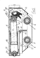
- a modular leading/trailing arm suspension assembly according to the invention indicated generally by the reference numeral 1.
- the assembly 1 is in this case in the form of a two wheel station module.
- a pair of suspension arms namely a leading forward suspension arm 2 and a trailing rear suspension arm 3 are pivotally mounted on a housing 4 containing spring means 5, 6 associated with each of the arms 2, 3 respectively.
- the housing 4 forms a support frame.
- Each suspension arm 2, 3 has an outer end 8 upon which are mounted a wheel support formed by a wheel hub assembly 9.
- the wheel hubs 9 are non-steering. It will be appreciated however that in other embodiments means may be provided for steering the hubs 9.
- each suspension arm 2, 3 is connected by a pivot shaft 11 with an associated lever arm 12 (Fig. 5) mounted within the housing 4.
- An upper end 13 of the lever arm 12 is connected to a spring element which in this case comprises a hydrostrut 14 which extends between the lever arm 12 and an inner side wall of the housing 4.
- the suspension arms 2, 3 are pivotable in a common vertical plane.
- Each pivot shaft 11 passes through an opening in a side wall of the housing 4.
- a seal 15 is mounted in said opening about the shaft 11 to seal between the housing 4 and the shaft 11.
- the lever arm 12 is provided with a resilient rebound stop 16 at the upper end 13 of the lever arm 12. This rebound stop 16 is engagable against an associated striking plate 17 on an inside face of a side wall of the housing 4.
- a swivel bearing 18 is mounted between the upper end 13 of the lever arm 12 and an inner end 19 of the hydrostrut 14.
- a second swivel bearing 20 is mounted between an outer end 21 of the hydrostrut 14 and an inner side wall of the housing 4 to transmit bump forces to the housing 4.
- each suspension arm 2, 3 rotates lies beneath the line of action Y of the hydrostrut 14 spring means.
- pivot shaft 11, lever arm 12 and hydrostrut assemblies associated with each of the suspension arms 2, 3 are mounted side by side in an overlapping arrangement which provides a compact configuration. Also, the reaction forces of the hydrostruts 14 oppose each other when the hydrostruts 14 are in this opposed side by side arrangement. The hydrostruts 14 are supported in a substantially horizontal orientation.
- the spring element is a hydrostrut 14 but in alternative embodiments various other spring media such as coil spring, rubber or any suitable elastic medium may be used.
- the mechanical rebound stops 16 react all the rebound forces directly on the housing 4 and likewise all the suspension bump forces are reacted directly into the housing 4 through the second bearings 20 mounted between each hydrostrut 14 and the housing 4. Both of the bearings 18, 20 allow pivoting movement at each end of the hydrostrut 14.
- Horizontal mounting plates or flanges are provided on the housing 4 comprising an inner mounting flange 30 and an outer mounting flange 31.
- the outer mounting flange 31 has a circular central pivot hole 32 on either side of which mounting slots 33 are provided. These mounting slots 33 are somewhat elongated and are for reception of undersize mounting bolts for attachment of the assembly 1 to an underside of a vehicle allowing some adjustment in a horizontal plane.
- the inner mounting flange 30 has a number of mounting slots 34 which are elongated and arranged such that a long axis of each slot 34 lies on the circumference of a circle having its centre at the pivot hole 32.
- pivot hole 32 can be engaged with a spigot, pivot pin or mounting bolt engaged with the pivot hole 32 and the underside of the vehicle and the whole assembly 1 can be pivoted about the pivot pin swinging about a vertical axis through the pivot pin (and pivot hole 32) for correct alignment of the assembly 1 on the vehicle body.
- mounting bolts are engaged through the slots 33, 34 to securely bolt the assembly 1 in position on the vehicle body.
- the arrangement for pivoting the suspension assembly 1 on the bottom of the vehicle for alignment of the suspension arms 2 can be achieved in a number of ways.
- a spigot or stud may project downwardly from the bottom of the vehicle hull to engage in the pivot hole 32.
- a pivot pin or stud may project upwardly from the mounting flange 31 to engage in a complementary mounting hole at the bottom of the vehicle hull.
- the key point is that the suspension system 1 can be offered up to the bottom of the vehicle and swivelled about a vertical axis for alignment of the two suspension arms 2, 3 and then bolted to the underside of the hull.
- the housing 4 will be inserted through an opening in the bottom of the hull and is protected within the hull during use.
- the mounting flanges 30, 31 project outwardly from the sides of the housing 4 just above the pivoting inner ends 10 of the suspension arms 2, 3.
- the housing 4 has a pair of box chambers 40 offset and projecting outwardly from opposite sides of a common central strut mounting plate 41.
- Cylindrical strut casings 42 each having a flanged inner end 43, are bolted to the strut mounting plate 41 to form an extension of each box chamber 40.
- the lever arm 12 and an inner end 19 of its associated hydrostrut 14 are housed within each box chamber 40 and the outer end 21 of the hydrostrut 14 is housed within the attached strut casing 42.
- the hydrostrut 14 passes through an opening 44 in the strut mounting plate 41.
- a removable access panel 45 is bolted over an access opening in a top of each box chamber 40.
- Split bearings 46 are mounted at the bottom of the housing 4 for rotatably supporting each pivot shaft 11, each of which extends between journal bearing mounts 47 at opposite sides of the housing 4.
- a lower bearing block part 48 is bolted to a complementary upper bearing block part 49 by bolts 49a.
- the invention provides a suspension assembly 1 of compact construction which can be mounted to an underside of the vehicle to minimise or eliminate intrusion into the interior volume of the vehicle.
- the modular assemblies are easy to fit and align on the vehicle body and require only one mounting point on the armoured hull. All of the interconnected moving elements and bearings are contained within a sealed housing. Also, all the bump and rebound forces are reacted within the assembly. While the inclusion of bump stops and rebound stops within the housing is desirable it is envisaged that in some configurations these may be omitted from the housing if desired.
- the front suspension arm 2 rises between the inner end 10 and outer end 8. When the vehicle hits a bump the front leading arm with wheel will rise and move rearwards relieving the loads. In similar fashion the trailing rear suspension arm 3 rises between its inner end 10 and outer end 8. This arrangement is best seen in Fig. 7.
- the suspension has zero net average torque applied to the hull mounting because the suspension arms produce opposite and on average equal torques.
- a drive train may be fed through the suspension arm.
- an electric motor could be provided in the hub and cabling and a cooling system delivered through the suspension arm through the electric motor.
- suspension module is completely self contained with bump and rebound stops installed within the assembly.
- the suspension module 1 is mounted underneath the hull floor and so does not intrude between the wheel and the hull wall, as with conventional designs. This enables the crew compartment width extend right out to the tyre side wall, maximising the interior width for any given overall width constraint.
- the under floor mounting of the suspension module 1 facilitates fore and aft alignment and allows the unit to be directly mounted to the hull without the necessity for machining of the mounting surface. Alignment may be done by means of slotted mounting holes laser cut in the hull plate prior to welding or by imbedding of suitable hard points in the case of non-metallic hulls.
- the under floor location gives a more benign load path than side wall mounting, especially in composite structures where side wall loadings from suspension mounts can lead to delamination of the wall.
- the hull structure can be lighter.
- the hydrostrut units are not exposed, as in conventional designs, but are in a dedicated enclosure within the hull, protected from ingress of mud and dirt which can lead to degradation of seals and premature failure, especially in prolonged service in harsh environments, with mud, dust and salt water exposure.
- Figs. 16 to 33 show various other embodiments of the invention and parts similar to those described previously are assigned the same reference numerals in these drawings.
- a vehicle 50 incorporating two of the suspension assemblies 1 described previously.
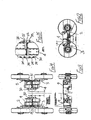
- the platform is an eight by eight wheeled configuration with conventional Ackerman type steering on the front four wheels 52 which in this case are located by a double wishbone suspension 53.
- Two pairs of rear wheels 55 are mounted on a hull 56 of the vehicle 50 by means of the suspension assemblies 1 which are bolted to the bottom of the hull 56.
- Fig. 17 shows four rear wheels 55 which are driven by conventional prop shafts 56 connecting the hubs 9 directly to differentials 57 which are mounted midships underneath the inner armour floor of the vehicle and connected by a drive transmission to an engine of the vehicle.
- the driveline is fitted with traction control, CTI, lockup and ABS.
- Fig. 18 an in-arm drive arrangement is shown in which drive to the hub 9 is delivered through the suspension arm 3.
- the drive is carried from a single differential to a splitter box integrated to the suspension module from which it is carried through the suspension arm journal by a shaft and down the suspension arm 2, 3 by a precision high performance inverted tooth chain drive indicated generally by the reference numeral 60.
- Figs. 19 and 20 show various electric drive arrangements with in-arm drive for use with the suspension assemblies 1.
- An in-arm driveline with a single differential per four wheel bogie lends itself very well to the incorporation of electric drive with either a single motor 63 as illustrated in Fig. 19, two motors 64 as illustrated in Fig. 20 or four motors.
- FIG. 21 to 23 an arrangement of the suspension assembly for a tracked vehicle 69 is shown, indicated generally by the reference numeral 60.
- this suspension assembly 60 a rocking beam 61 is mounted at an outer end of each suspension arm 2, 3.
- a centre 62 of each rocking beam 61 is pivotally mounted on the suspension arm 2, 3 by a pivot pin 64 for pivotal movement about a horizontal pivot axis.
- Bushings 65 at each end of the rocking beam 61 receive pivot shafts 66 carrying pairs of wheels 67 for engaging and supporting a track 68 on the vehicle 69.
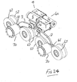
- Figs. 24 to 30 there is shown another variation in this case for a hybridised track/wheel design.
- This is similar to the suspension assembly 60 described with reference to Figs. 21 to 23.
- a wheel support hub 70 mounted co-axially with the pivot pins 64 of the rocking beams 61.
- the wheel hubs 70 carry wheels 71 as shown in Figs. 26 and 27 which extend below the track 68.
- the track wheels 67 are sized so that the track 68 is some distance above the ground contact point of the road wheels 71. All road wheels 71 are fitted with in-hub motors and directional control is by skid steering.
- the tracks are not required to operate on hard, broken terrain to the same extent as those on a conventional tracked vehicle would be the track structure and weight can be significantly reduced compared to a normal track. Also, since the wheels do contribute significantly to floatation and traction in soft ground, the tracks may be narrower than would be required on a tracked vehicle.
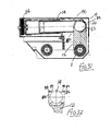
- Figs. 31 and 32 there is shown another suspension assembly indicated generally by the reference numeral 80.
- the lever arm 12 is connected at its upper end to the hydrostrut 14 by means of a fork and trunnion connector indicated generally by the reference numeral 82.
- the other end of the hydrostrut 14 is mounted on the wall of the housing 4 by an elastomeric flexible mounting 84.
- the connector 82 is formed by laterally projecting trunnion pins 86 on the hydrostrut 14 which are rotatably journalled in associated bearing holes 87 in forked arms 88 at an upper end of the lever arm 12. This construction advantageously allows the length of the housing 4 to be reduced providing a more compact modular construction for the suspension assembly 80.
- a pair of the suspension assemblies 1 are each mounted in a bogie arrangement for swivelling about a vertical axis on the underside of the vehicle hull.
- Each wheel 90 is pivotally mounted on the suspension arms 2, 3 at 91.
- a steering arm 92 mounted on the wheel sub axle is pivotally joined to a fixed point 93 by means of a drag link 94.
- a bogie track rod 95 is provided between the two bogies.
- the drag link mounting point 93 may be provided with a means to alter its position such that no relative movement of the wheel 90 and bogie occurs.
Landscapes
- Engineering & Computer Science (AREA)
- Mechanical Engineering (AREA)
- Chemical & Material Sciences (AREA)
- Combustion & Propulsion (AREA)
- Transportation (AREA)
- Vehicle Body Suspensions (AREA)
- Automobile Manufacture Line, Endless Track Vehicle, Trailer (AREA)
- Mechanical Operated Clutches (AREA)
- Electrical Discharge Machining, Electrochemical Machining, And Combined Machining (AREA)
- Surgical Instruments (AREA)
Applications Claiming Priority (2)
| Application Number | Priority Date | Filing Date | Title |
|---|---|---|---|
| IE20020431A IES20020431A2 (en) | 2002-05-30 | 2002-05-30 | A trailing arm suspension assembly |
| IE20020431 | 2002-05-30 |
Publications (3)
| Publication Number | Publication Date |
|---|---|
| EP1366972A2 true EP1366972A2 (de) | 2003-12-03 |
| EP1366972A3 EP1366972A3 (de) | 2004-09-08 |
| EP1366972B1 EP1366972B1 (de) | 2009-08-26 |
Family
ID=29415755
Family Applications (1)
| Application Number | Title | Priority Date | Filing Date |
|---|---|---|---|
| EP03394047A Expired - Lifetime EP1366972B1 (de) | 2002-05-30 | 2003-05-30 | Längsarmaufhängung |
Country Status (7)
| Country | Link |
|---|---|
| US (1) | US7111857B2 (de) |
| EP (1) | EP1366972B1 (de) |
| AT (1) | ATE440767T1 (de) |
| DE (1) | DE60328940D1 (de) |
| IE (1) | IES20020431A2 (de) |
| SG (1) | SG123559A1 (de) |
| TW (1) | TW584706B (de) |
Cited By (3)
| Publication number | Priority date | Publication date | Assignee | Title |
|---|---|---|---|---|
| RU2422292C1 (ru) * | 2010-02-01 | 2011-06-27 | Владимир Никитич Тарасов | Подвеска танка |
| RU2506190C1 (ru) * | 2012-05-25 | 2014-02-10 | Федеральное Государственное Бюджетное Образовательное Учреждение Высшего Профессионального Образования Дальневосточный Государственный Аграрный Университет | Ход гусеничный |
| DE102023108856B3 (de) | 2023-04-06 | 2024-09-05 | charismaTec OG | Fahrzeug |
Families Citing this family (22)
| Publication number | Priority date | Publication date | Assignee | Title |
|---|---|---|---|---|
| US6761234B1 (en) * | 2003-06-26 | 2004-07-13 | Case, Llc | Skid steer vehicle with steerable suspension |
| US7296642B1 (en) * | 2004-02-18 | 2007-11-20 | Dana Corporation | Suspended axle modules for skid steer loaders |
| US20050205329A1 (en) * | 2004-02-25 | 2005-09-22 | Shimon Fanger-Vexler | Vehicle and vehicle drive-through suspension arm |
| US7294082B2 (en) * | 2004-12-21 | 2007-11-13 | Chrysler Llc | Powertrain arrangement for a skid-steer vehicle |
| GB0507134D0 (en) * | 2005-04-08 | 2005-05-18 | Casani Juan C M | Improvements in and relating to suspension assemblies |
| GR1006455B (el) * | 2008-06-25 | 2009-06-22 | Αθανασιου Δημητριος Χατζηκακιδης | Παραμετρικο συστημα πλαισιου για οχηματα σχηματιζομενο απο τεσσερα στοιχεια αναρτησεως με εγκαρσια ραβδο στρεψεως και ομοαξονικο συστημα αποσβεστηρα μεσα σε φατνωμα που επιτρεπει την αποθηκευση κεντρικα βαρεων στοιχειων (οπως μπαταριες) |
| US8182193B2 (en) * | 2008-10-28 | 2012-05-22 | Max-Atlas | Trailer for transporting freight containers and method of use |
| CA2693511C (en) | 2009-02-18 | 2016-02-23 | L'equipe Fabconcept Inc. | Vehicle suspension system |
| DE102010043040B4 (de) * | 2010-10-28 | 2025-06-18 | Zf Friedrichshafen Ag | Verfahren zur Herstellung eines Fahrwerkbauteils |
| CA2962801C (en) * | 2014-09-29 | 2021-08-24 | Soucy International Inc. | Track system having low vibrations |
| US10640160B2 (en) | 2014-09-29 | 2020-05-05 | Soucy International Inc. | Progressive damping system for a track system |
| US10526027B2 (en) | 2014-09-29 | 2020-01-07 | Soucy International Inc. | Damping system for an endless track system |
| US10633044B2 (en) | 2014-09-29 | 2020-04-28 | Soucy International Inc. | Dynamic tensioner locking device for a track system and method thereof |
| US10668962B2 (en) | 2014-09-29 | 2020-06-02 | Soucy International Inc. | Track system |
| EP3372424A1 (de) * | 2017-03-07 | 2018-09-12 | Volvo Construction Equipment AB | Arbeitsmaschine und verfahren zum abfedern einer arbeitsmaschine |
| GB2562539A (en) * | 2017-05-19 | 2018-11-21 | Bamford Excavators Ltd | Working machine |
| US10933929B1 (en) | 2017-11-20 | 2021-03-02 | Soucy International Inc. | Track system for a vehicle |
| CN111923720B (zh) * | 2019-10-24 | 2021-10-29 | 中国北方车辆研究所 | 一种四连杆型轮毂电机纵臂悬架 |
| KR102313267B1 (ko) * | 2021-04-14 | 2021-10-14 | 서한산업(주) | 전동식 독립 조향장치 |
| CN113352834B (zh) * | 2021-06-03 | 2022-10-14 | 中国北方车辆研究所 | 多模式可调模块化行动系统 |
| US11772442B2 (en) * | 2021-07-23 | 2023-10-03 | Rivian Ip Holdings, Llc | Offset steering axis knuckle system |
| KR20240043826A (ko) * | 2022-09-27 | 2024-04-04 | 현대자동차주식회사 | 차량용 서스펜션 장치 |
Citations (3)
| Publication number | Priority date | Publication date | Assignee | Title |
|---|---|---|---|---|
| GB484648A (en) | 1936-09-15 | 1938-05-09 | Ansaldo Societa Anonima | Elastic suspension system for endless track vehicles |
| US3923112A (en) | 1974-01-07 | 1975-12-02 | Muriel T Goodgame | Driven wheel arrangement |
| US4600069A (en) | 1982-09-28 | 1986-07-15 | Standard Manufacturing Company, Inc. | Trailing arm suspension |
Family Cites Families (6)
| Publication number | Priority date | Publication date | Assignee | Title |
|---|---|---|---|---|
| DE874405C (de) * | 1951-03-01 | 1953-04-23 | Bergische Achsen Kotz Soehne | Kraftfahrzeug oder Kraftfahrzeuganhaenger mit Pendelachsen |
| US3760763A (en) * | 1971-02-26 | 1973-09-25 | A Brusacoram | All terrain vehicle |
| US4519654A (en) * | 1983-12-20 | 1985-05-28 | Caterpillar Tractor Co. | Roller suspension apparatus for a belted vehicle |
| US4871188A (en) * | 1987-02-02 | 1989-10-03 | Baxter Bobby G | Wheeled vehicle suspension |
| RU2043208C1 (ru) * | 1992-03-17 | 1995-09-10 | Акционерное общество "Контес" | Балансирная подвеска сдвоенных осей транспортного средства |
| US6527286B2 (en) * | 2000-12-06 | 2003-03-04 | The Boler Company | Vehicle suspension assembly |
-
2002
- 2002-05-30 IE IE20020431A patent/IES20020431A2/en not_active IP Right Cessation
-
2003
- 2003-05-30 DE DE60328940T patent/DE60328940D1/de not_active Expired - Fee Related
- 2003-05-30 SG SG200303033A patent/SG123559A1/en unknown
- 2003-05-30 AT AT03394047T patent/ATE440767T1/de not_active IP Right Cessation
- 2003-05-30 EP EP03394047A patent/EP1366972B1/de not_active Expired - Lifetime
- 2003-05-30 US US10/448,191 patent/US7111857B2/en not_active Expired - Fee Related
- 2003-05-30 TW TW092114766A patent/TW584706B/zh not_active IP Right Cessation
Patent Citations (3)
| Publication number | Priority date | Publication date | Assignee | Title |
|---|---|---|---|---|
| GB484648A (en) | 1936-09-15 | 1938-05-09 | Ansaldo Societa Anonima | Elastic suspension system for endless track vehicles |
| US3923112A (en) | 1974-01-07 | 1975-12-02 | Muriel T Goodgame | Driven wheel arrangement |
| US4600069A (en) | 1982-09-28 | 1986-07-15 | Standard Manufacturing Company, Inc. | Trailing arm suspension |
Cited By (3)
| Publication number | Priority date | Publication date | Assignee | Title |
|---|---|---|---|---|
| RU2422292C1 (ru) * | 2010-02-01 | 2011-06-27 | Владимир Никитич Тарасов | Подвеска танка |
| RU2506190C1 (ru) * | 2012-05-25 | 2014-02-10 | Федеральное Государственное Бюджетное Образовательное Учреждение Высшего Профессионального Образования Дальневосточный Государственный Аграрный Университет | Ход гусеничный |
| DE102023108856B3 (de) | 2023-04-06 | 2024-09-05 | charismaTec OG | Fahrzeug |
Also Published As
| Publication number | Publication date |
|---|---|
| EP1366972A3 (de) | 2004-09-08 |
| US7111857B2 (en) | 2006-09-26 |
| ATE440767T1 (de) | 2009-09-15 |
| US20040032107A1 (en) | 2004-02-19 |
| DE60328940D1 (de) | 2009-10-08 |
| TW584706B (en) | 2004-04-21 |
| EP1366972B1 (de) | 2009-08-26 |
| IES20020431A2 (en) | 2003-12-10 |
| TW200307804A (en) | 2003-12-16 |
| SG123559A1 (en) | 2006-07-26 |
Similar Documents
| Publication | Publication Date | Title |
|---|---|---|
| EP1366972B1 (de) | Längsarmaufhängung | |
| EP3708467B1 (de) | Anordnung mit einem gleitplattenmodul | |
| US8251385B2 (en) | Multi-pivot vehicle suspension | |
| US10435075B2 (en) | Suspension module having a subframe assembly | |
| EP3705321B1 (de) | Aufhängungssystem | |
| JP3847785B2 (ja) | 大型ダンプトラックサスペンション | |
| CA1307556C (en) | Suspension structure for a tracked vehicle | |
| US7703781B2 (en) | Suspensions for low floor vehicle | |
| US11014421B2 (en) | Recreational off-highway vehicle | |
| JP3300345B2 (ja) | 大型車両と大型車両の積荷担持ボディ | |
| US10737719B2 (en) | Steerable knuckle | |
| US7798506B2 (en) | Wheel suspension system for vehicles | |
| US6105984A (en) | Independent coil spring suspension for driven wheels | |
| JPH07237567A (ja) | クローラベルト式車両の懸架装置 | |
| GB2425511A (en) | Suspension retraction arrangement for an amphibious vehicle | |
| US10717465B2 (en) | Steerable knuckle | |
| US8739917B2 (en) | Off-road vehicles | |
| US20050093260A1 (en) | Non co-planar rear suspension for heavy trucks | |
| RU2198107C2 (ru) | Двухосное колесное транспортное средство | |
| JPH06278431A (ja) | 車両のサスペンション装置 | |
| JP2000016106A (ja) | ホイールクレーン | |
| JP2002178919A (ja) | 軌道車両 | |
| IES83366Y1 (en) | A trailing arm suspension assembly | |
| US20120061935A1 (en) | Axle Arrangement | |
| CN121361326A (zh) | 一种集成多种行驶模式的双轮独立驱动轮组 |
Legal Events
| Date | Code | Title | Description |
|---|---|---|---|
| PUAI | Public reference made under article 153(3) epc to a published international application that has entered the european phase |
Free format text: ORIGINAL CODE: 0009012 |
|
| AK | Designated contracting states |
Kind code of ref document: A2 Designated state(s): AT BE BG CH CY CZ DE DK EE ES FI FR GB GR HU IE IT LI LU MC NL PT RO SE SI SK TR |
|
| AX | Request for extension of the european patent |
Extension state: AL LT LV MK |
|
| PUAL | Search report despatched |
Free format text: ORIGINAL CODE: 0009013 |
|
| AK | Designated contracting states |
Kind code of ref document: A3 Designated state(s): AT BE BG CH CY CZ DE DK EE ES FI FR GB GR HU IE IT LI LU MC NL PT RO SE SI SK TR |
|
| AX | Request for extension of the european patent |
Extension state: AL LT LV MK |
|
| 17P | Request for examination filed |
Effective date: 20050307 |
|
| AKX | Designation fees paid |
Designated state(s): AT BE BG CH CY CZ DE DK EE ES FI FR GB GR HU IE IT LI LU MC NL PT RO SE SI SK TR |
|
| 17Q | First examination report despatched |
Effective date: 20061129 |
|
| GRAP | Despatch of communication of intention to grant a patent |
Free format text: ORIGINAL CODE: EPIDOSNIGR1 |
|
| GRAS | Grant fee paid |
Free format text: ORIGINAL CODE: EPIDOSNIGR3 |
|
| GRAA | (expected) grant |
Free format text: ORIGINAL CODE: 0009210 |
|
| AK | Designated contracting states |
Kind code of ref document: B1 Designated state(s): AT BE BG CH CY CZ DE DK EE ES FI FR GB GR HU IE IT LI LU MC NL PT RO SE SI SK TR |
|
| REG | Reference to a national code |
Ref country code: GB Ref legal event code: FG4D |
|
| REG | Reference to a national code |
Ref country code: CH Ref legal event code: EP |
|
| REG | Reference to a national code |
Ref country code: IE Ref legal event code: FG4D |
|
| REF | Corresponds to: |
Ref document number: 60328940 Country of ref document: DE Date of ref document: 20091008 Kind code of ref document: P |
|
| REG | Reference to a national code |
Ref country code: SE Ref legal event code: TRGR |
|
| PG25 | Lapsed in a contracting state [announced via postgrant information from national office to epo] |
Ref country code: AT Free format text: LAPSE BECAUSE OF FAILURE TO SUBMIT A TRANSLATION OF THE DESCRIPTION OR TO PAY THE FEE WITHIN THE PRESCRIBED TIME-LIMIT Effective date: 20090826 Ref country code: FI Free format text: LAPSE BECAUSE OF FAILURE TO SUBMIT A TRANSLATION OF THE DESCRIPTION OR TO PAY THE FEE WITHIN THE PRESCRIBED TIME-LIMIT Effective date: 20090826 |
|
| NLV1 | Nl: lapsed or annulled due to failure to fulfill the requirements of art. 29p and 29m of the patents act | ||
| PG25 | Lapsed in a contracting state [announced via postgrant information from national office to epo] |
Ref country code: NL Free format text: LAPSE BECAUSE OF FAILURE TO SUBMIT A TRANSLATION OF THE DESCRIPTION OR TO PAY THE FEE WITHIN THE PRESCRIBED TIME-LIMIT Effective date: 20090826 Ref country code: SI Free format text: LAPSE BECAUSE OF FAILURE TO SUBMIT A TRANSLATION OF THE DESCRIPTION OR TO PAY THE FEE WITHIN THE PRESCRIBED TIME-LIMIT Effective date: 20090826 |
|
| PG25 | Lapsed in a contracting state [announced via postgrant information from national office to epo] |
Ref country code: BG Free format text: LAPSE BECAUSE OF FAILURE TO SUBMIT A TRANSLATION OF THE DESCRIPTION OR TO PAY THE FEE WITHIN THE PRESCRIBED TIME-LIMIT Effective date: 20091126 Ref country code: PT Free format text: LAPSE BECAUSE OF FAILURE TO SUBMIT A TRANSLATION OF THE DESCRIPTION OR TO PAY THE FEE WITHIN THE PRESCRIBED TIME-LIMIT Effective date: 20091228 Ref country code: CY Free format text: LAPSE BECAUSE OF FAILURE TO SUBMIT A TRANSLATION OF THE DESCRIPTION OR TO PAY THE FEE WITHIN THE PRESCRIBED TIME-LIMIT Effective date: 20090826 |
|
| PG25 | Lapsed in a contracting state [announced via postgrant information from national office to epo] |
Ref country code: RO Free format text: LAPSE BECAUSE OF FAILURE TO SUBMIT A TRANSLATION OF THE DESCRIPTION OR TO PAY THE FEE WITHIN THE PRESCRIBED TIME-LIMIT Effective date: 20090826 Ref country code: DK Free format text: LAPSE BECAUSE OF FAILURE TO SUBMIT A TRANSLATION OF THE DESCRIPTION OR TO PAY THE FEE WITHIN THE PRESCRIBED TIME-LIMIT Effective date: 20090826 Ref country code: CZ Free format text: LAPSE BECAUSE OF FAILURE TO SUBMIT A TRANSLATION OF THE DESCRIPTION OR TO PAY THE FEE WITHIN THE PRESCRIBED TIME-LIMIT Effective date: 20090826 Ref country code: ES Free format text: LAPSE BECAUSE OF FAILURE TO SUBMIT A TRANSLATION OF THE DESCRIPTION OR TO PAY THE FEE WITHIN THE PRESCRIBED TIME-LIMIT Effective date: 20091207 Ref country code: EE Free format text: LAPSE BECAUSE OF FAILURE TO SUBMIT A TRANSLATION OF THE DESCRIPTION OR TO PAY THE FEE WITHIN THE PRESCRIBED TIME-LIMIT Effective date: 20090826 |
|
| PG25 | Lapsed in a contracting state [announced via postgrant information from national office to epo] |
Ref country code: SK Free format text: LAPSE BECAUSE OF FAILURE TO SUBMIT A TRANSLATION OF THE DESCRIPTION OR TO PAY THE FEE WITHIN THE PRESCRIBED TIME-LIMIT Effective date: 20090826 |
|
| PG25 | Lapsed in a contracting state [announced via postgrant information from national office to epo] |
Ref country code: BE Free format text: LAPSE BECAUSE OF FAILURE TO SUBMIT A TRANSLATION OF THE DESCRIPTION OR TO PAY THE FEE WITHIN THE PRESCRIBED TIME-LIMIT Effective date: 20090826 |
|
| PLBE | No opposition filed within time limit |
Free format text: ORIGINAL CODE: 0009261 |
|
| STAA | Information on the status of an ep patent application or granted ep patent |
Free format text: STATUS: NO OPPOSITION FILED WITHIN TIME LIMIT |
|
| 26N | No opposition filed |
Effective date: 20100527 |
|
| PG25 | Lapsed in a contracting state [announced via postgrant information from national office to epo] |
Ref country code: GR Free format text: LAPSE BECAUSE OF FAILURE TO SUBMIT A TRANSLATION OF THE DESCRIPTION OR TO PAY THE FEE WITHIN THE PRESCRIBED TIME-LIMIT Effective date: 20091127 |
|
| PG25 | Lapsed in a contracting state [announced via postgrant information from national office to epo] |
Ref country code: MC Free format text: LAPSE BECAUSE OF NON-PAYMENT OF DUE FEES Effective date: 20100531 |
|
| REG | Reference to a national code |
Ref country code: CH Ref legal event code: PL |
|
| REG | Reference to a national code |
Ref country code: FR Ref legal event code: ST Effective date: 20110131 |
|
| PG25 | Lapsed in a contracting state [announced via postgrant information from national office to epo] |
Ref country code: LI Free format text: LAPSE BECAUSE OF NON-PAYMENT OF DUE FEES Effective date: 20100531 Ref country code: CH Free format text: LAPSE BECAUSE OF NON-PAYMENT OF DUE FEES Effective date: 20100531 |
|
| PG25 | Lapsed in a contracting state [announced via postgrant information from national office to epo] |
Ref country code: IT Free format text: LAPSE BECAUSE OF FAILURE TO SUBMIT A TRANSLATION OF THE DESCRIPTION OR TO PAY THE FEE WITHIN THE PRESCRIBED TIME-LIMIT Effective date: 20090826 |
|
| PG25 | Lapsed in a contracting state [announced via postgrant information from national office to epo] |
Ref country code: DE Free format text: LAPSE BECAUSE OF NON-PAYMENT OF DUE FEES Effective date: 20101201 |
|
| PG25 | Lapsed in a contracting state [announced via postgrant information from national office to epo] |
Ref country code: FR Free format text: LAPSE BECAUSE OF NON-PAYMENT OF DUE FEES Effective date: 20100531 |
|
| PG25 | Lapsed in a contracting state [announced via postgrant information from national office to epo] |
Ref country code: LU Free format text: LAPSE BECAUSE OF NON-PAYMENT OF DUE FEES Effective date: 20100530 Ref country code: HU Free format text: LAPSE BECAUSE OF FAILURE TO SUBMIT A TRANSLATION OF THE DESCRIPTION OR TO PAY THE FEE WITHIN THE PRESCRIBED TIME-LIMIT Effective date: 20100227 |
|
| PG25 | Lapsed in a contracting state [announced via postgrant information from national office to epo] |
Ref country code: TR Free format text: LAPSE BECAUSE OF FAILURE TO SUBMIT A TRANSLATION OF THE DESCRIPTION OR TO PAY THE FEE WITHIN THE PRESCRIBED TIME-LIMIT Effective date: 20090826 |
|
| PGFP | Annual fee paid to national office [announced via postgrant information from national office to epo] |
Ref country code: GB Payment date: 20160531 Year of fee payment: 14 Ref country code: IE Payment date: 20160531 Year of fee payment: 14 |
|
| PGFP | Annual fee paid to national office [announced via postgrant information from national office to epo] |
Ref country code: SE Payment date: 20160523 Year of fee payment: 14 |
|
| REG | Reference to a national code |
Ref country code: SE Ref legal event code: EUG |
|
| GBPC | Gb: european patent ceased through non-payment of renewal fee |
Effective date: 20170530 |
|
| REG | Reference to a national code |
Ref country code: IE Ref legal event code: MM4A |
|
| PG25 | Lapsed in a contracting state [announced via postgrant information from national office to epo] |
Ref country code: SE Free format text: LAPSE BECAUSE OF NON-PAYMENT OF DUE FEES Effective date: 20170531 |
|
| PG25 | Lapsed in a contracting state [announced via postgrant information from national office to epo] |
Ref country code: GB Free format text: LAPSE BECAUSE OF NON-PAYMENT OF DUE FEES Effective date: 20170530 Ref country code: IE Free format text: LAPSE BECAUSE OF NON-PAYMENT OF DUE FEES Effective date: 20170530 |