EP1367250B1 - Ensemble de compresseur booster contrarotatif pour une turbine à gaz - Google Patents
Ensemble de compresseur booster contrarotatif pour une turbine à gaz Download PDFInfo
- Publication number
- EP1367250B1 EP1367250B1 EP03251104.0A EP03251104A EP1367250B1 EP 1367250 B1 EP1367250 B1 EP 1367250B1 EP 03251104 A EP03251104 A EP 03251104A EP 1367250 B1 EP1367250 B1 EP 1367250B1
- Authority
- EP
- European Patent Office
- Prior art keywords
- fan blade
- counter
- fan
- compressor
- booster compressor
- Prior art date
- Legal status (The legal status is an assumption and is not a legal conclusion. Google has not performed a legal analysis and makes no representation as to the accuracy of the status listed.)
- Expired - Lifetime
Links
- 238000011144 upstream manufacturing Methods 0.000 claims description 9
- 239000007789 gas Substances 0.000 description 15
- 239000003570 air Substances 0.000 description 5
- 239000000567 combustion gas Substances 0.000 description 3
- 230000035945 sensitivity Effects 0.000 description 2
- 239000012080 ambient air Substances 0.000 description 1
- 239000000446 fuel Substances 0.000 description 1
- 230000000717 retained effect Effects 0.000 description 1
- 238000007789 sealing Methods 0.000 description 1
Images



Classifications
-
- F—MECHANICAL ENGINEERING; LIGHTING; HEATING; WEAPONS; BLASTING
- F02—COMBUSTION ENGINES; HOT-GAS OR COMBUSTION-PRODUCT ENGINE PLANTS
- F02K—JET-PROPULSION PLANTS
- F02K3/00—Plants including a gas turbine driving a compressor or a ducted fan
- F02K3/02—Plants including a gas turbine driving a compressor or a ducted fan in which part of the working fluid by-passes the turbine and combustion chamber
- F02K3/04—Plants including a gas turbine driving a compressor or a ducted fan in which part of the working fluid by-passes the turbine and combustion chamber the plant including ducted fans, i.e. fans with high volume, low pressure outputs, for augmenting the jet thrust, e.g. of double-flow type
- F02K3/072—Plants including a gas turbine driving a compressor or a ducted fan in which part of the working fluid by-passes the turbine and combustion chamber the plant including ducted fans, i.e. fans with high volume, low pressure outputs, for augmenting the jet thrust, e.g. of double-flow type with counter-rotating, e.g. fan rotors
-
- F—MECHANICAL ENGINEERING; LIGHTING; HEATING; WEAPONS; BLASTING
- F01—MACHINES OR ENGINES IN GENERAL; ENGINE PLANTS IN GENERAL; STEAM ENGINES
- F01D—NON-POSITIVE DISPLACEMENT MACHINES OR ENGINES, e.g. STEAM TURBINES
- F01D5/00—Blades; Blade-carrying members; Heating, heat-insulating, cooling or antivibration means on the blades or the members
- F01D5/02—Blade-carrying members, e.g. rotors
- F01D5/022—Blade-carrying members, e.g. rotors with concentric rows of axial blades
-
- F—MECHANICAL ENGINEERING; LIGHTING; HEATING; WEAPONS; BLASTING
- F01—MACHINES OR ENGINES IN GENERAL; ENGINE PLANTS IN GENERAL; STEAM ENGINES
- F01D—NON-POSITIVE DISPLACEMENT MACHINES OR ENGINES, e.g. STEAM TURBINES
- F01D5/00—Blades; Blade-carrying members; Heating, heat-insulating, cooling or antivibration means on the blades or the members
- F01D5/02—Blade-carrying members, e.g. rotors
- F01D5/03—Annular blade-carrying members having blades on the inner periphery of the annulus and extending inwardly radially, i.e. inverted rotors
-
- F—MECHANICAL ENGINEERING; LIGHTING; HEATING; WEAPONS; BLASTING
- F02—COMBUSTION ENGINES; HOT-GAS OR COMBUSTION-PRODUCT ENGINE PLANTS
- F02C—GAS-TURBINE PLANTS; AIR INTAKES FOR JET-PROPULSION PLANTS; CONTROLLING FUEL SUPPLY IN AIR-BREATHING JET-PROPULSION PLANTS
- F02C3/00—Gas-turbine plants characterised by the use of combustion products as the working fluid
- F02C3/04—Gas-turbine plants characterised by the use of combustion products as the working fluid having a turbine driving a compressor
- F02C3/06—Gas-turbine plants characterised by the use of combustion products as the working fluid having a turbine driving a compressor the compressor comprising only axial stages
- F02C3/067—Gas-turbine plants characterised by the use of combustion products as the working fluid having a turbine driving a compressor the compressor comprising only axial stages having counter-rotating rotors
Definitions
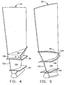
- a flow path represented by an arrow 72 for fan 12 is defined by a fan casing 74 and a hub 76 for first fan stage 16 (see Fig. 2 ). It will be seen that flow path 72 is then preferably divided upstream of second fan stage 20, where an outer portion represented by an arrow 78 bypasses the rest of engine 10 (except for passing through second fan stage 20) and an inner portion represented by arrow 80 is directed into booster compressor 36 and an inlet duct 82 to high pressure compressor 28. It will be appreciated that a splitter nose 84 is provided in order to divide flow path 72, which will be discussed in greater detail herein.
Landscapes
- Engineering & Computer Science (AREA)
- Mechanical Engineering (AREA)
- General Engineering & Computer Science (AREA)
- Chemical & Material Sciences (AREA)
- Combustion & Propulsion (AREA)
- Structures Of Non-Positive Displacement Pumps (AREA)
- Turbine Rotor Nozzle Sealing (AREA)
Claims (10)
- Ensemble de compresseur accélérateur contrarotatif (36) pour une turbine à gaz (10) ayant une section de soufflante contrarotative (12) avec une première rangée de pales de soufflante (18) raccordée à un premier arbre d'entraînement (46) et une seconde rangée de pales de soufflante (22) axialement espacée de ladite première rangée de pales de soufflante (18) et raccordée à un second arbre d'entraînement (48), ledit ensemble de compresseur accélérateur contrarotatif (36) comprenant :(a) une première rangée de pales de compresseur (38) raccordée audit premier arbre d'entraînement (46) ; et(b) une seconde rangée de pales de compresseur (40) imbriquée dans ladite première rangée de pales de compresseur (38) et raccordée audit second arbre d'entraînement (48) ; dans lequel une partie (102) de chaque pale de soufflante (22) de ladite seconde rangée de pales de soufflante (22) s'étend à travers un trajet d'écoulement (80) dudit compresseur accélérateur contrarotatif (36) de manière à fonctionner comme pale de compresseur (104) dans ladite seconde rangée de pales de compresseur (40), chaque dite pale de soufflante de ladite seconde rangée de pales de soufflante étant en outre caractérisée en ce qu'elle comprend :(a) un premier élément de plate-forme formé d'une seule pièce avec chaque dite pale de soufflante de ladite seconde rangée de pales de soufflante à un premier emplacement de manière à former un trajet d'écoulement interne pour ledit compresseur accélérateur contrarotatif ; et(b) un deuxième élément de plate-forme formé d'une seule pièce avec chaque dite pale de soufflante de ladite seconde rangée de pales de soufflante à un deuxième emplacement de manière à former un trajet d'écoulement interne pour ledit compresseur accélérateur contrarotatif.
- Ensemble de compresseur accélérateur contrarotatif (36) selon la revendication 1, comprenant en outre un troisième élément de plate-forme (86) formé d'une seule pièce avec chaque dite pale de soufflante (22) de ladite seconde rangée de pales de soufflante (22) à un troisième emplacement de manière à former un trajet d'écoulement interne pour ladite section de soufflante contrarotative (12).
- Ensemble de compresseur accélérateur contrarotatif (36) selon la revendication 2, lesdits deuxième et troisième éléments de plate-forme (96, 86) étant joints l'un à l'autre à une extrémité amont pour former une bride amont (106).
- Ensemble de compresseur accélérateur contrarotatif (36) selon la revendication 3, comprenant en outre une bobine accélératrice en amont de ladite seconde rangée de pales de soufflante (22) raccordée à ladite bride amont (106), ladite bobine accélératrice comprenant au moins une pale de compresseur (112) qui s'étend à partir de celle-ci et qui tourne en conformité avec ladite seconde rangée de pales de soufflante (22).
- Ensemble de compresseur accélérateur contrarotatif (36) selon la revendication 1, comprenant en outre une aube de guidage de sortie (42) positionnée dans ledit trajet d'écoulement (80) de l'accélérateur en aval de ladite seconde rangée de pales de soufflante (22).
- Ensemble de compresseur accélérateur contrarotatif (36) selon la revendication 1, dans lequel ledit compresseur accélérateur (36) est situé entre lesdites première et seconde rangées de pales de soufflante (18, 22).
- Ensemble de compresseur accélérateur contrarotatif (36) selon la revendication 1, comprenant en outre un disque (98) pour retenir ladite seconde rangée de pales de soufflante (22), dans lequel ledit disque (98) est raccordé audit second arbre d'entraînement (48).
- Ensemble de compresseur accélérateur contrarotatif (36) selon la revendication 1, comprenant en outre une pale de compresseur accélérateur supplémentaire (114) située adjacente à au moins certaines desdites pales de soufflante (22) de ladite seconde rangée de pales de soufflante (22), lesdites pales de compresseur accélérateur supplémentaires (114) s'étendant entre lesdits premier et deuxième éléments de plate-forme (94, 96) et étant raccordées à ceux-ci.
- Ensemble de pales de soufflante selon la revendication 8, dans lequel lesdites pales de compresseur accélérateur supplémentaires (114) ont une largeur qui est inférieure à la largeur desdites parties de pales de soufflante (102) fonctionnant comme pale de compresseur (104).
- Ensemble de pales de soufflante selon la revendication 9, dans lequel un bord d'attaque (116) desdites pales de compresseur accélérateur supplémentaires (114) est positionné sensiblement en alignement avec un bord d'attaque (118) pour lesdites parties de pales de soufflante (102) fonctionnant comme pale de compresseur (104).
Applications Claiming Priority (2)
| Application Number | Priority Date | Filing Date | Title |
|---|---|---|---|
| US134172 | 2002-04-29 | ||
| US10/134,172 US6739120B2 (en) | 2002-04-29 | 2002-04-29 | Counterrotatable booster compressor assembly for a gas turbine engine |
Publications (2)
| Publication Number | Publication Date |
|---|---|
| EP1367250A1 EP1367250A1 (fr) | 2003-12-03 |
| EP1367250B1 true EP1367250B1 (fr) | 2014-01-01 |
Family
ID=29249156
Family Applications (1)
| Application Number | Title | Priority Date | Filing Date |
|---|---|---|---|
| EP03251104.0A Expired - Lifetime EP1367250B1 (fr) | 2002-04-29 | 2003-02-25 | Ensemble de compresseur booster contrarotatif pour une turbine à gaz |
Country Status (3)
| Country | Link |
|---|---|
| US (1) | US6739120B2 (fr) |
| EP (1) | EP1367250B1 (fr) |
| JP (1) | JP4204349B2 (fr) |
Families Citing this family (65)
| Publication number | Priority date | Publication date | Assignee | Title |
|---|---|---|---|---|
| US6684626B1 (en) * | 2002-07-30 | 2004-02-03 | General Electric Company | Aircraft gas turbine engine with control vanes for counter rotating low pressure turbines |
| US6763653B2 (en) * | 2002-09-24 | 2004-07-20 | General Electric Company | Counter rotating fan aircraft gas turbine engine with aft booster |
| US6763652B2 (en) * | 2002-09-24 | 2004-07-20 | General Electric Company | Variable torque split aircraft gas turbine engine counter rotating low pressure turbines |
| US7100358B2 (en) * | 2004-07-16 | 2006-09-05 | Pratt & Whitney Canada Corp. | Turbine exhaust case and method of making |
| US7458202B2 (en) * | 2004-10-29 | 2008-12-02 | General Electric Company | Lubrication system for a counter-rotating turbine engine and method of assembling same |
| US7290386B2 (en) | 2004-10-29 | 2007-11-06 | General Electric Company | Counter-rotating gas turbine engine and method of assembling same |
| US7334392B2 (en) * | 2004-10-29 | 2008-02-26 | General Electric Company | Counter-rotating gas turbine engine and method of assembling same |
| US7195447B2 (en) * | 2004-10-29 | 2007-03-27 | General Electric Company | Gas turbine engine and method of assembling same |
| US7186073B2 (en) * | 2004-10-29 | 2007-03-06 | General Electric Company | Counter-rotating gas turbine engine and method of assembling same |
| US7334981B2 (en) * | 2004-10-29 | 2008-02-26 | General Electric Company | Counter-rotating gas turbine engine and method of assembling same |
| US7409819B2 (en) * | 2004-10-29 | 2008-08-12 | General Electric Company | Gas turbine engine and method of assembling same |
| US7296398B2 (en) * | 2004-10-29 | 2007-11-20 | General Electric Company | Counter-rotating turbine engine and method of assembling same |
| US7195446B2 (en) * | 2004-10-29 | 2007-03-27 | General Electric Company | Counter-rotating turbine engine and method of assembling same |
| US7269938B2 (en) * | 2004-10-29 | 2007-09-18 | General Electric Company | Counter-rotating gas turbine engine and method of assembling same |
| US7594388B2 (en) * | 2005-06-06 | 2009-09-29 | General Electric Company | Counterrotating turbofan engine |
| FR2889863B1 (fr) * | 2005-08-22 | 2007-11-02 | Snecma | Compresseur comportant une pluralite de caissons reconstituant un volume annulaire de separation de flux dans une turbomachine. |
| US7752836B2 (en) * | 2005-10-19 | 2010-07-13 | General Electric Company | Gas turbine assembly and methods of assembling same |
| US7490461B2 (en) * | 2005-10-19 | 2009-02-17 | General Electric Company | Gas turbine engine assembly and methods of assembling same |
| US7726113B2 (en) * | 2005-10-19 | 2010-06-01 | General Electric Company | Gas turbine engine assembly and methods of assembling same |
| US7513103B2 (en) * | 2005-10-19 | 2009-04-07 | General Electric Company | Gas turbine engine assembly and methods of assembling same |
| US7685808B2 (en) * | 2005-10-19 | 2010-03-30 | General Electric Company | Gas turbine engine assembly and methods of assembling same |
| US7493753B2 (en) * | 2005-10-19 | 2009-02-24 | General Electric Company | Gas turbine engine assembly and methods of assembling same |
| US7603844B2 (en) * | 2005-10-19 | 2009-10-20 | General Electric Company | Gas turbine engine assembly and methods of assembling same |
| US7493754B2 (en) * | 2005-10-19 | 2009-02-24 | General Electric Company | Gas turbine engine assembly and methods of assembling same |
| US7490460B2 (en) * | 2005-10-19 | 2009-02-17 | General Electric Company | Gas turbine engine assembly and methods of assembling same |
| US7526913B2 (en) * | 2005-10-19 | 2009-05-05 | General Electric Company | Gas turbine engine assembly and methods of assembling same |
| DE102006001909B4 (de) * | 2006-01-14 | 2010-06-10 | Howden Ventilatoren Gmbh | Laufrad eines Ventilators |
| US8016561B2 (en) * | 2006-07-11 | 2011-09-13 | General Electric Company | Gas turbine engine fan assembly and method for assembling to same |
| US7694505B2 (en) * | 2006-07-31 | 2010-04-13 | General Electric Company | Gas turbine engine assembly and method of assembling same |
| US20080075590A1 (en) * | 2006-09-27 | 2008-03-27 | Thomas Ory Moniz | Gas turbine engine assembly and method of assembling same |
| US7832193B2 (en) * | 2006-10-27 | 2010-11-16 | General Electric Company | Gas turbine engine assembly and methods of assembling same |
| US7926259B2 (en) * | 2006-10-31 | 2011-04-19 | General Electric Company | Turbofan engine assembly and method of assembling same |
| US7966806B2 (en) * | 2006-10-31 | 2011-06-28 | General Electric Company | Turbofan engine assembly and method of assembling same |
| US7841165B2 (en) * | 2006-10-31 | 2010-11-30 | General Electric Company | Gas turbine engine assembly and methods of assembling same |
| RU2349503C1 (ru) * | 2007-07-18 | 2009-03-20 | Владимир Дмитриевич Гречишников | Несущий винт |
| US8708643B2 (en) * | 2007-08-14 | 2014-04-29 | General Electric Company | Counter-rotatable fan gas turbine engine with axial flow positive displacement worm gas generator |
| US8590286B2 (en) * | 2007-12-05 | 2013-11-26 | United Technologies Corp. | Gas turbine engine systems involving tip fans |
| US8015798B2 (en) * | 2007-12-13 | 2011-09-13 | United Technologies Corporation | Geared counter-rotating gas turbofan engine |
| US8292570B2 (en) * | 2008-01-25 | 2012-10-23 | United Technologies Corporation | Low pressure turbine with counter-rotating drives for single spool |
| EP2123884B1 (fr) * | 2008-05-13 | 2015-03-04 | Rolls-Royce Corporation | Agencement d'embrayage double |
| US20100005810A1 (en) * | 2008-07-11 | 2010-01-14 | Rob Jarrell | Power transmission among shafts in a turbine engine |
| US8480527B2 (en) * | 2008-08-27 | 2013-07-09 | Rolls-Royce Corporation | Gearing arrangement |
| US8166748B2 (en) * | 2008-11-21 | 2012-05-01 | General Electric Company | Gas turbine engine booster having rotatable radially inwardly extending blades and non-rotatable vanes |
| US8011877B2 (en) * | 2008-11-24 | 2011-09-06 | General Electric Company | Fiber composite reinforced aircraft gas turbine engine drums with radially inwardly extending blades |
| US8021267B2 (en) * | 2008-12-11 | 2011-09-20 | Rolls-Royce Corporation | Coupling assembly |
| US8075438B2 (en) * | 2008-12-11 | 2011-12-13 | Rolls-Royce Corporation | Apparatus and method for transmitting a rotary input into counter-rotating outputs |
| EP3135920B1 (fr) * | 2008-12-31 | 2018-12-19 | Rolls-Royce North American Technologies, Inc. | Compresseur à taux de compression variable |
| US8375695B2 (en) * | 2009-06-30 | 2013-02-19 | General Electric Company | Aircraft gas turbine engine counter-rotatable generator |
| FR2948973B1 (fr) * | 2009-08-05 | 2011-10-14 | Snecma | Moyeu d'helice a pales a calage variable |
| US8063528B2 (en) * | 2009-12-18 | 2011-11-22 | General Electric Company | Counter-rotatable generator |
| US9410427B2 (en) * | 2012-06-05 | 2016-08-09 | United Technologies Corporation | Compressor power and torque transmitting hub |
| US9752500B2 (en) * | 2013-03-14 | 2017-09-05 | Pratt & Whitney Canada Corp. | Gas turbine engine with transmission and method of adjusting rotational speed |
| US10669947B2 (en) | 2016-07-11 | 2020-06-02 | Raytheon Technologies Corporation | Geared gas turbine engine |
| US10557373B2 (en) * | 2017-12-05 | 2020-02-11 | United Technologies Corporation | Low profile embedded blade tip clearance probe assembly |
| US10641595B2 (en) * | 2018-04-09 | 2020-05-05 | United Technologies Corporation | Low profile triaxial blade tip clearance probe assembly with driven guard |
| US11143142B2 (en) | 2018-08-01 | 2021-10-12 | United Technologies Corporation | Adaptive engine with boost spool |
| US11028778B2 (en) | 2018-09-27 | 2021-06-08 | Pratt & Whitney Canada Corp. | Engine with start assist |
| US11753939B2 (en) | 2019-02-20 | 2023-09-12 | General Electric Company | Turbomachine with alternatingly spaced rotor blades |
| US11156097B2 (en) | 2019-02-20 | 2021-10-26 | General Electric Company | Turbomachine having an airflow management assembly |
| US11085515B2 (en) | 2019-02-20 | 2021-08-10 | General Electric Company | Gearbox coupling in a turbomachine |
| US11073088B2 (en) | 2019-02-20 | 2021-07-27 | General Electric Company | Gearbox mounting in a turbomachine |
| US11021970B2 (en) | 2019-02-20 | 2021-06-01 | General Electric Company | Turbomachine with alternatingly spaced rotor blades |
| GB202114773D0 (en) | 2021-10-15 | 2021-12-01 | Rolls Royce Plc | Bladed disc |
| US12247516B2 (en) * | 2022-09-29 | 2025-03-11 | General Electric Company | Counter-rotating gas turbine engines including turbine sections with separable torque frames |
| US12565855B1 (en) | 2025-02-14 | 2026-03-03 | General Electric Company | Gas turbine engine |
Family Cites Families (17)
| Publication number | Priority date | Publication date | Assignee | Title |
|---|---|---|---|---|
| FR1555814A (fr) * | 1967-12-12 | 1969-01-31 | ||
| GB1305302A (fr) * | 1970-04-28 | 1973-01-31 | ||
| DE2149619A1 (de) * | 1971-10-05 | 1973-04-19 | Motoren Turbinen Union | Turbinenstrahltriebwerk fuer senkrechtoder kurzstartende bzw. landende flugzeuge |
| US3903690A (en) * | 1973-02-12 | 1975-09-09 | Gen Electric | Turbofan engine lubrication means |
| GB1484898A (en) * | 1974-09-11 | 1977-09-08 | Rolls Royce | Ducted fan gas turbine engine |
| US4791783A (en) * | 1981-11-27 | 1988-12-20 | General Electric Company | Convertible aircraft engine |
| US4790133A (en) | 1986-08-29 | 1988-12-13 | General Electric Company | High bypass ratio counterrotating turbofan engine |
| US4860537A (en) | 1986-08-29 | 1989-08-29 | Brandt, Inc. | High bypass ratio counterrotating gearless front fan engine |
| GB2195712B (en) | 1986-10-08 | 1990-08-29 | Rolls Royce Plc | A turbofan gas turbine engine |
| US4976102A (en) | 1988-05-09 | 1990-12-11 | General Electric Company | Unducted, counterrotating gearless front fan engine |
| US5345760A (en) | 1993-02-05 | 1994-09-13 | General Electric Company | Turboprop booster |
| US5443590A (en) | 1993-06-18 | 1995-08-22 | General Electric Company | Rotatable turbine frame |
| US5307622A (en) | 1993-08-02 | 1994-05-03 | General Electric Company | Counterrotating turbine support assembly |
| US5388964A (en) * | 1993-09-14 | 1995-02-14 | General Electric Company | Hybrid rotor blade |
| US6158210A (en) | 1998-12-03 | 2000-12-12 | General Electric Company | Gear driven booster |
| US6220012B1 (en) | 1999-05-10 | 2001-04-24 | General Electric Company | Booster recirculation passageway and methods for recirculating air |
| USH2032H1 (en) | 1999-10-01 | 2002-07-02 | The United States Of America As Represented By The Secretary Of The Air Force | Integrated fan-core twin spool counter-rotating turbofan gas turbine engine |
-
2002
- 2002-04-29 US US10/134,172 patent/US6739120B2/en not_active Expired - Fee Related
-
2003
- 2003-02-25 EP EP03251104.0A patent/EP1367250B1/fr not_active Expired - Lifetime
- 2003-02-28 JP JP2003052194A patent/JP4204349B2/ja not_active Expired - Fee Related
Also Published As
| Publication number | Publication date |
|---|---|
| EP1367250A1 (fr) | 2003-12-03 |
| JP2003322027A (ja) | 2003-11-14 |
| JP4204349B2 (ja) | 2009-01-07 |
| US6739120B2 (en) | 2004-05-25 |
| US20030200741A1 (en) | 2003-10-30 |
Similar Documents
| Publication | Publication Date | Title |
|---|---|---|
| EP1367250B1 (fr) | Ensemble de compresseur booster contrarotatif pour une turbine à gaz | |
| EP1365154B1 (fr) | Ensemble compresseur booster à contre-rotation pour turbine à gaz | |
| JP4588306B2 (ja) | 非交互嵌合二重反転式低圧タービンを備えた航空機用ガスタービンエンジン | |
| JP4346375B2 (ja) | 低圧タービンを二重反転させるための制御ベーンを備えた航空機用ガスタービンエンジン | |
| EP1403485B1 (fr) | Turbine à gaz avec une turbine basse pression comprenant des turbines basse pression avec tiges internes et externes contrarotatifs | |
| EP1403500B1 (fr) | Réacteur comprenant des turbines contrarotatives basse pression à répartition variable de couple, des soufflantes contrarotatives, ainsi qu'un booster non contrarotatif | |
| EP1403499B1 (fr) | Turbine à gas pour les avions avec soufflante contrarotative et subséquent compresseur à basse pression | |
| EP1825111B1 (fr) | Carter de compresseur à rotation inverse pour un moteur à turbine en bout | |
| EP1626002B1 (fr) | Turbine d'un moteur à turbine à gaz | |
| EP1834071B1 (fr) | Inducteur de pale de ventilateur de moteur de turbine a pression d'entree | |
| CA2567940C (fr) | Methodes et dispositifs applicables aux turbines a gaz | |
| CN112443364B (zh) | 用于同心可变定子静叶的促动组件 |
Legal Events
| Date | Code | Title | Description |
|---|---|---|---|
| PUAI | Public reference made under article 153(3) epc to a published international application that has entered the european phase |
Free format text: ORIGINAL CODE: 0009012 |
|
| AK | Designated contracting states |
Kind code of ref document: A1 Designated state(s): AT BE BG CH CY CZ DE DK EE ES FI FR GB GR HU IE IT LI LU MC NL PT SE SI SK TR |
|
| AX | Request for extension of the european patent |
Extension state: AL LT LV MK RO |
|
| 17P | Request for examination filed |
Effective date: 20040603 |
|
| 17Q | First examination report despatched |
Effective date: 20040714 |
|
| AKX | Designation fees paid |
Designated state(s): DE FR GB IT |
|
| GRAP | Despatch of communication of intention to grant a patent |
Free format text: ORIGINAL CODE: EPIDOSNIGR1 |
|
| INTG | Intention to grant announced |
Effective date: 20130801 |
|
| GRAS | Grant fee paid |
Free format text: ORIGINAL CODE: EPIDOSNIGR3 |
|
| GRAA | (expected) grant |
Free format text: ORIGINAL CODE: 0009210 |
|
| AK | Designated contracting states |
Kind code of ref document: B1 Designated state(s): DE FR GB IT |
|
| REG | Reference to a national code |
Ref country code: GB Ref legal event code: FG4D |
|
| REG | Reference to a national code |
Ref country code: DE Ref legal event code: R096 Ref document number: 60345536 Country of ref document: DE Effective date: 20140220 |
|
| REG | Reference to a national code |
Ref country code: DE Ref legal event code: R097 Ref document number: 60345536 Country of ref document: DE |
|
| PLBE | No opposition filed within time limit |
Free format text: ORIGINAL CODE: 0009261 |
|
| STAA | Information on the status of an ep patent application or granted ep patent |
Free format text: STATUS: NO OPPOSITION FILED WITHIN TIME LIMIT |
|
| 26N | No opposition filed |
Effective date: 20141002 |
|
| REG | Reference to a national code |
Ref country code: DE Ref legal event code: R097 Ref document number: 60345536 Country of ref document: DE Effective date: 20141002 |
|
| REG | Reference to a national code |
Ref country code: FR Ref legal event code: PLFP Year of fee payment: 13 |
|
| PGFP | Annual fee paid to national office [announced via postgrant information from national office to epo] |
Ref country code: IT Payment date: 20150225 Year of fee payment: 13 Ref country code: DE Payment date: 20150226 Year of fee payment: 13 |
|
| PGFP | Annual fee paid to national office [announced via postgrant information from national office to epo] |
Ref country code: FR Payment date: 20150217 Year of fee payment: 13 Ref country code: GB Payment date: 20150226 Year of fee payment: 13 |
|
| REG | Reference to a national code |
Ref country code: DE Ref legal event code: R119 Ref document number: 60345536 Country of ref document: DE |
|
| GBPC | Gb: european patent ceased through non-payment of renewal fee |
Effective date: 20160225 |
|
| REG | Reference to a national code |
Ref country code: FR Ref legal event code: ST Effective date: 20161028 |
|
| PG25 | Lapsed in a contracting state [announced via postgrant information from national office to epo] |
Ref country code: IT Free format text: LAPSE BECAUSE OF NON-PAYMENT OF DUE FEES Effective date: 20160225 |
|
| PG25 | Lapsed in a contracting state [announced via postgrant information from national office to epo] |
Ref country code: FR Free format text: LAPSE BECAUSE OF NON-PAYMENT OF DUE FEES Effective date: 20160229 Ref country code: DE Free format text: LAPSE BECAUSE OF NON-PAYMENT OF DUE FEES Effective date: 20160901 Ref country code: GB Free format text: LAPSE BECAUSE OF NON-PAYMENT OF DUE FEES Effective date: 20160225 |