EP1367272A2 - Kugelgelenkdichtung - Google Patents
Kugelgelenkdichtung Download PDFInfo
- Publication number
- EP1367272A2 EP1367272A2 EP03011191A EP03011191A EP1367272A2 EP 1367272 A2 EP1367272 A2 EP 1367272A2 EP 03011191 A EP03011191 A EP 03011191A EP 03011191 A EP03011191 A EP 03011191A EP 1367272 A2 EP1367272 A2 EP 1367272A2
- Authority
- EP
- European Patent Office
- Prior art keywords
- spring
- seal
- stud
- ball joint
- spring fingers
- Prior art date
- Legal status (The legal status is an assumption and is not a legal conclusion. Google has not performed a legal analysis and makes no representation as to the accuracy of the status listed.)
- Granted
Links
Images


Classifications
-
- F—MECHANICAL ENGINEERING; LIGHTING; HEATING; WEAPONS; BLASTING
- F16—ENGINEERING ELEMENTS AND UNITS; GENERAL MEASURES FOR PRODUCING AND MAINTAINING EFFECTIVE FUNCTIONING OF MACHINES OR INSTALLATIONS; THERMAL INSULATION IN GENERAL
- F16C—SHAFTS; FLEXIBLE SHAFTS; ELEMENTS OR CRANKSHAFT MECHANISMS; ROTARY BODIES OTHER THAN GEARING ELEMENTS; BEARINGS
- F16C11/00—Pivots; Pivotal connections
- F16C11/04—Pivotal connections
- F16C11/06—Ball-joints; Other joints having more than one degree of angular freedom, i.e. universal joints
- F16C11/0666—Sealing means between the socket and the inner member shaft
- F16C11/0671—Sealing means between the socket and the inner member shaft allowing operative relative movement of joint parts due to flexing of the sealing means
-
- F—MECHANICAL ENGINEERING; LIGHTING; HEATING; WEAPONS; BLASTING
- F16—ENGINEERING ELEMENTS AND UNITS; GENERAL MEASURES FOR PRODUCING AND MAINTAINING EFFECTIVE FUNCTIONING OF MACHINES OR INSTALLATIONS; THERMAL INSULATION IN GENERAL
- F16J—PISTONS; CYLINDERS; SEALINGS
- F16J3/00—Diaphragms; Bellows; Bellows pistons
- F16J3/04—Bellows
- F16J3/041—Non-metallic bellows
- F16J3/042—Fastening details
-
- F—MECHANICAL ENGINEERING; LIGHTING; HEATING; WEAPONS; BLASTING
- F16—ENGINEERING ELEMENTS AND UNITS; GENERAL MEASURES FOR PRODUCING AND MAINTAINING EFFECTIVE FUNCTIONING OF MACHINES OR INSTALLATIONS; THERMAL INSULATION IN GENERAL
- F16C—SHAFTS; FLEXIBLE SHAFTS; ELEMENTS OR CRANKSHAFT MECHANISMS; ROTARY BODIES OTHER THAN GEARING ELEMENTS; BEARINGS
- F16C11/00—Pivots; Pivotal connections
- F16C11/04—Pivotal connections
- F16C11/06—Ball-joints; Other joints having more than one degree of angular freedom, i.e. universal joints
- F16C11/0619—Ball-joints; Other joints having more than one degree of angular freedom, i.e. universal joints the female part comprising a blind socket receiving the male part
- F16C11/0623—Construction or details of the socket member
- F16C11/0628—Construction or details of the socket member with linings
-
- F—MECHANICAL ENGINEERING; LIGHTING; HEATING; WEAPONS; BLASTING
- F16—ENGINEERING ELEMENTS AND UNITS; GENERAL MEASURES FOR PRODUCING AND MAINTAINING EFFECTIVE FUNCTIONING OF MACHINES OR INSTALLATIONS; THERMAL INSULATION IN GENERAL
- F16C—SHAFTS; FLEXIBLE SHAFTS; ELEMENTS OR CRANKSHAFT MECHANISMS; ROTARY BODIES OTHER THAN GEARING ELEMENTS; BEARINGS
- F16C2326/00—Articles relating to transporting
- F16C2326/20—Land vehicles
- F16C2326/24—Steering systems, e.g. steering rods or columns
-
- Y—GENERAL TAGGING OF NEW TECHNOLOGICAL DEVELOPMENTS; GENERAL TAGGING OF CROSS-SECTIONAL TECHNOLOGIES SPANNING OVER SEVERAL SECTIONS OF THE IPC; TECHNICAL SUBJECTS COVERED BY FORMER USPC CROSS-REFERENCE ART COLLECTIONS [XRACs] AND DIGESTS
- Y10—TECHNICAL SUBJECTS COVERED BY FORMER USPC
- Y10T—TECHNICAL SUBJECTS COVERED BY FORMER US CLASSIFICATION
- Y10T403/00—Joints and connections
- Y10T403/32—Articulated members
- Y10T403/32606—Pivoted
- Y10T403/32631—Universal ball and socket
-
- Y—GENERAL TAGGING OF NEW TECHNOLOGICAL DEVELOPMENTS; GENERAL TAGGING OF CROSS-SECTIONAL TECHNOLOGIES SPANNING OVER SEVERAL SECTIONS OF THE IPC; TECHNICAL SUBJECTS COVERED BY FORMER USPC CROSS-REFERENCE ART COLLECTIONS [XRACs] AND DIGESTS
- Y10—TECHNICAL SUBJECTS COVERED BY FORMER USPC
- Y10T—TECHNICAL SUBJECTS COVERED BY FORMER US CLASSIFICATION
- Y10T403/00—Joints and connections
- Y10T403/32—Articulated members
- Y10T403/32606—Pivoted
- Y10T403/32631—Universal ball and socket
- Y10T403/32729—Externally packed
Definitions
- the present invention relates to a ball joint and, in particular, to a seal for a ball joint.
- a typical ball joint includes a socket and a ball stud.
- the ball stud has a ball end portion received in the socket and a shank portion projecting from the ball stud.
- the socket supports the ball stud for pivotal movement relative to the socket with the shank portion extending from the socket.
- the ball joint also includes a seal that has a first end portion that seals against the socket.
- a second end portion of the seal seals against the shank portion of the ball stud.
- the seal prevents lubricant from coming out of the ball joint and also prevents dirt and other items from entering into the ball joint.
- the second end portion of the seal may wear against the ball stud, but still needs to be kept in sealing engagement.
- the present invention is a ball joint comprising a socket defining a pivot center, a bearing in the socket, and a stud having a ball end portion received in the bearing and a shank portion projecting from the socket.
- the stud has a longitudinal axis extending through the pivot center.
- the bearing supports the stud in the socket for pivotal movement about the pivot center.
- the ball joint further comprises an annular seal having an intermediate portion extending between first and second end portions of the seal. The first end portion of the seal is fixed to the socket. The second end portion of the seal has an engagement portion in sealing engagement with the shank portion of the stud.
- the seal includes a spring molded in the second end portion of the seal and extending for 360 degrees around the circumference of the shank portion of the stud at a location radially outward of the engagement portion of the seal.
- the spring has a main body portion and a circular array of spring fingers that extend radially inward from the main body portion and exert a radially inward directed force on the engagement portion of the seal to maintain the engagement portion of the seal in sealing engagement with the shank portion of the stud.
- the present invention relates to a ball joint for supporting a first vehicle portion for movement relative to a second vehicle portion.
- the present invention is applicable to various ball joint constructions.
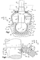
- Fig. 1 illustrates a ball joint 10.
- the ball joint 10 is located between a first vehicle portion shown partially at 12 and a second vehicle portion shown schematically and partially at 14.
- the first vehicle portion 12 may be a steering knuckle or steering yoke, for example.
- the first vehicle portion 12 has a cylindrical opening 16 for receiving the ball joint 10.
- the second vehicle portion 14 may be a control arm or steering yoke or steering knuckle, for example.
- the second vehicle portion 14 has a frustoconical surface that defines a tapered bore or opening indicated at 18.
- the ball joint 10 is generally of a conventional construction and includes a socket 30 and a steel ball stud 40.
- the socket 30 is mounted in the opening 16 in the first vehicle portion 12.
- a mounting flange 32 extends radially outward from a side wall 34 of the socket 30, spaced from a closed lower end 36 of the socket.
- a bearing 38 is located in the socket 30.
- a ball end portion 42 of the ball stud 40 is received in the bearing 38.
- the ball end portion 42 of the ball stud 40 is pivotable and rotatable in the bearing 38, about a pivot center 43, to provide for relative movement between the first vehicle portion 12 and the ball stud 40.
- the ball stud 40 has a shank portion 50 that projects from the ball end portion.
- the shank portion 50 has a cylindrical first section 52 centered on a longitudinal central axis 56 of the ball stud 40.
- the axis 56 extends through the pivot center 43.
- the first section has a cylindrical outer surface 58.
- the shank portion 50 also has a second section 60 that has a tapered outer surface centered on the axis 56.
- the shank portion 50 also has a threaded end section 62.
- the tapered portion 60 of the shank 50 is fitted in the tapered opening 18 in the second vehicle portion in a tight, force-fitting connection.
- a nut (not shown) is screwed on the threaded end section 60 of the ball stud 40 to secure the connection.
- the ball joint 10 further includes a seal 70.
- the seal 70 extends between the socket 30 and the first section 52 of the ball stud 40.
- the seal 70 has a first end portion 72 connected with the socket 30 and a second end portion 74 connected with the ball stud 40.
- the seal 70 includes a seal member 80 and a retainer ring, or spring, 90.
- the seal member 80 is made from an elastomeric material.
- the elastomeric material is selected to have good flex fatigue life, puncture resistance, and abrasion resistance, etc.
- the seal member 80 has a first end portion 82 fixedly connected with the socket 30.
- the first end portion 82 seals against the socket 30 and forms the first end portion 72 of the seal 70.
- the seal member 80 has a second end portion 86.
- the second end portion 86 of the seal member 80 is adjacent to and connected with the shank portion 50 of the ball stud 40 in a manner described below.
- the second end portion 86 of the seal member 80 forms part of the second end portion 74 of the seal 70.
- the second end portion 86 of the seal member 80 is pivotable with the ball stud 40.
- the shank portion 50 of the ball stud 40 is rotatable relative to the second end portion 80 of the seal member 80.
- the seal member 80 also has a main body portion 88.
- the main body portion 88 of the seal member 80 extends between and interconnects the first end portion 72 of the seal 70 and the second end portion 74 of the seal.
- the main body portion 88 of the seal member 80 forms a main body portion of the seal 70 itself.
- the retainer ring, or spring, 90 is molded within the second end portion 86 of the seal member 80.
- the spring 90 is made from a plastic material, as described below.
- the spring 90 forms part of the second end portion 74 of the seal 70, together with the second end portion 86 of the seal member 80.
- the spring 90 has an annular configuration that extends for 360 degrees around the shank portion 50 of the ball stud 40.
- the spring 90 has a main body portion 92 that has a ring-shaped or annular configuration.
- the main body portion 92 is located on the outer periphery of the spring 90.
- the main body portion 92 of the spring 90 has a cylindrical outer side surface 94 that extends axially between parallel, annular, radially extending upper and lower end surfaces 96 and 98.
- the terms “upper” and “lower” are used herein to describe the orientation of the spring as viewed in Figs. 1-3 and 5, and are not limiting structurally.
- the arrow 100 indicates an "upward” direction
- the arrow 102 indicates an opposite, "downward” direction.
- the spring 90 includes a plurality of tangs, or spring fingers, or fingers 104.
- the fingers 104 extend radially inward from the inner periphery of the main body portion 92 of the spring 96, in a direction toward the axis 56. In the illustrated embodiment, thirty-six fingers 104 are provided on the spring 90. A larger or smaller number of fingers 104 can be provided, dependent on the diameter of the spring 90, among other factors.
- the plurality of fingers 104 includes a first plurality or group of fingers that are referred to herein as "upper fingers” 106, and a second plurality or group of fingers that are referred to herein as “lower fingers” 108. All the upper fingers 106 are identical to each other. All the lower fingers 108 are identical to each other.
- the upper fingers 106 are mirror images of the lower fingers 108, in a top-to-bottom manner.
- an upper finger 106 when viewed from above in Fig. 5, appears identical to a lower finger 108, when viewed from below in Fig. 5.
- the upper fingers 106 are interspersed with the lower fingers 108 around the inner periphery of the main body portion 92 of the spring 90. Specifically, the upper fingers 106 are disposed in an alternating relationship with the lower fingers 108 around the axis 56. Each one of the upper fingers 106 is located between two adjacent lower fingers 108, and each one of the lower fingers 108 is located between two adjacent upper fingers 106. There is a gap between each two adjacent fingers 106, 108.
- the spring 90 can be molded into the seal member 80 in either orientation-upper end surface 96 or lower end surface 98 facing toward the socket 12-and will function the same. This feature provides for ease of assembly.
- spring fingers 106 and 108 are identical to each other, one particular upper spring 110 finger shown in Fig. 6 is described in detail, with regard to its surfaces and the portions those surfaces define.
- the reference numerals for the surfaces and portions of the spring finger 110 are, in the drawings, sometimes used on other spring fingers of the spring 90.
- the finger 110 has two side surfaces 112 and 114 that extend radially inward from the main body portion 92 in a direction toward the axis 56.
- the side surfaces 112 and 114 converge in a direction toward the axis 56.
- the finger 110 has a decreasing circumferential extent, or tapers, as it extends radially inward from the main body portion 92 of the spring 90.
- the side surface 112 on each finger 104 is adjacent to, but spaced apart from, the side surface 114 of the adjacent finger 104, to define the gap between them.
- the finger 110 includes a first surface 116 that extends radially inward as an extension of the upper end surface 96.
- the first surface 116 is planar, and has an arcuate configuration centered on the axis 56, as viewed from above in Fig. 5, and as seen in Fig. 4. (Dot-dash lines are used in Fig. 6 to identify the divisions between adjacent surfaces.)
- a second surface 118 extends axially from the first surface 116, in a direction perpendicular to the first surface and toward the plane of the lower end surface 98.
- the second surface 118 has an axial extent of about one third the axial extent of the outer side surface 94.
- the second surface 118 has a radially inwardly facing cylindrical configuration centered on the axis 56, as best seen in Fig. 4.
- a third surface 120 extends generally radially inward from the second surface 118.
- the third surface 120 has an axially bowed configuration that is convex in the upward direction 100.
- the third surface 120 as viewed from above in Fig. 5, or as seen in Fig. 4, has an arcuate configuration centered on the axis 56.
- a fourth surface 122 extends axially upward from the third surface 120, in a direction toward the plane of the upper end surface 96 and parallel to the second surface 118.
- the fourth surface 122 has an axial extent slightly less than that of the second surface 118, and terminates short of the plane of the upper end surface 96.
- the fourth surface 122 has a radially outwardly facing cylindrical configuration centered on the axis 56, as best seen in Fig. 4.
- a fifth surface 124 extends radially inward from the fourth surface 122 in a direction perpendicular to the fourth surface and parallel to the plane of the upper end surface 96.
- the fifth surface 124 is planar, and has an arcuate configuration centered on the axis 56, as viewed from above in Fig. 5, and as seen in Fig. 4.
- a sixth surface 126 extends axially downward from the fifth surface 124, in a direction toward the plane of the lower end surface 98 and parallel to the second surface 118 and the fourth surface 122.
- the sixth surface 126 terminates short of the plane of the lower end surface 98.
- the sixth surface 126 has a radially inwardly facing cylindrical configuration centered on the axis 56, as best seen in Fig. 4.
- the sixth surface 126 is the radially innermost surface of the finger 110.
- a seventh surface 128 extends radially inward from the sixth surface 126.
- the seventh surface 128 is similar to the fifth surface 124.
- the seventh surface 128 is planar, and has an arcuate configuration centered on the axis 56, as viewed from below in Fig. 5, and as seen in Fig. 4.
- An eighth surface 130 extends axially upward from the seventh surface 128, in a direction toward the plane of the upper end surface 96 and parallel to the sixth surface 126.
- the eighth 130 surface has an axial extent slightly less than that of the fourth surface 122.
- the eighth surface 130 has a radially outwardly facing cylindrical configuration centered on the axis 56, as best seen in Fig. 4.
- the eighth surface 130 is similar to the fourth surface 122.
- a ninth surface 132 extends generally radially outward from the eighth surface 130.
- the ninth surface 132 has an axially bowed configuration that is concave in the downward direction 102 and extends parallel to the bowed third surface 120.
- the ninth surface 132 as viewed from below in Fig. 5, or as seen in Fig. 4, has an arcuate configuration centered on the axis 56.
- a tenth surface 134 extends axially downward from the ninth surface 132, terminating in the plane of the lower end surface 98.
- the tenth surface 134 has a radially inwardly facing cylindrical configuration centered on the axis 56, as best seen in Fig. 4.
- An eleventh surface 136 extends radially outward from the tenth surface 134.
- the eleventh surface 136 is planar, and has an arcuate configuration centered on the axis 56, as viewed from below in Fig. 5, and as seen in Fig. 4.
- a twelfth surface 138 extends axially upward from the eleventh surface 136, terminating at about the level of the third surface 120.
- the twelfth surface 138 has a radially outwardly facing cylindrical configuration centered on the axis 56, as best seen in Fig. 4.
- a thirteenth surface 140 extends generally radially outward from the twelfth surface 138.
- the thirteenth surface 140 has an axially bowed configuration that is concave in the downward direction 102.
- the thirteenth surface 140 as viewed from below in Fig. 5, or as seen in Fig. 4, has an arcuate configuration centered on the axis 56.
- a fourteenth surface 142 extends axially downward from the thirteenth surface 140, terminating at the lower end surface 98 of the main body portion 92 of the spring 90.
- the fourteenth surface 142 has a cylindrical configuration centered on the axis 56, as best seen in Fig. 4.
- the surfaces 112-142 of the spring finger 110 define a plurality of portions of the spring finger.
- the portions are not physically discrete, but are identified thus as they have specific separable functions.
- the spring finger 110 includes a first cantilever portion, or outer cantilever portion designated 150 in Fig. 5.
- the outer cantilever portion 150 extends generally radially inward, from the main body portion 92.
- the outer cantilever portion 150 is bounded or defined axially by the first surface 116 on top and the thirteenth surface 140 on the bottom.
- the spring finger 110 includes an annular outer rib portion, or outer rib, designated 152 in Fig. 5.
- the outer rib 152 extends axially downward from the radially inner end of the outer cantilever portion 150.
- the outer rib 152 is supported on the spring main body portion 92 by the outer cantilever portion 150.
- the outer rib 152 is defined by the first surface 116, the second surface 118, the tenth surface 134, the eleventh surface 136, and the twelfth surface 138.
- the spring finger 110 includes a second cantilever portion, or inner cantilever portion designated 154 in Fig. 5.
- the inner cantilever portion 154 extends generally radially inward from the outer rib 152.
- the inner cantilever portion 154 is defined axially by the third surface 120 on top and the ninth surface 132 on the bottom, and thus has a bowed configuration.
- the spring finger 110 includes an inner rib portion, or inner rib, designated 156 in Fig. 5.
- the inner rib 156 extends axially both upward and downward from the radially inner end of the inner cantilever portion 154.
- the inner rib 156 is supported on the outer rib 152 by the inner cantilever portion 154.
- the inner rib 156 is defined by the fourth, fifth, sixth, seventh, and eighth surfaces 122-130, respectively.
- the inner rib 156 is the portion of the spring finger 110 that is farthest radially inward.
- the sixth surface 126 on the inner rib 156 is the surface of the spring finger 110 that is farthest radially inward.
- the sixth surface 126 is curved in a cylindrical configuration centered on the axis 56.
- the spring 90 is preferably injection molded, and preferably from a resilient plastic material.
- the material is selected to provide a spring force to the upper and lower fingers 106 and 108, when one part of the spring 90 is acted upon by force tending to move it relative to another part of the spring.
- the inner rib 156 is resiliently movable relative to the outer rib 152, upon deformation or bending of the inner cantilever portion 154.
- a radially outwardly directed force on the inner rib 156 causes the inner cantilever portion 154 to deflect, bowing in the upward direction 100, and the inner rib 156 moves radially outward toward the outer rib 152.
- the outer rib 152 is resiliently movable relative to the main body portion 92 of the spring, upon deformation or bending of the outer cantilever portion 150.
- a radially outwardly directed force on the outer rib 152 causes the outer cantilever portion 150 to deflect, bowing in the upward direction 100, and the outer rib 152 moves radially outward toward the main body portion 92.
- the outer cantilever portion 150 is radially shorter than the inner cantilever portion 154, the outer rib 152 is not deflectable as much as the inner rib 156. The primary radial deflection in the spring 90 occurs by deformation of the inner cantilever portion 154.
- the spring 90 (Fig. 2) is molded in the seal member 80, the spring is substantially completely enclosed in the material of the seal member, except at one annular groove area 158 located on the second end portion 86 of the seal member 80.
- An engagement portion 160 of the seal member 80 is disposed radially inward of the spring 90.
- the engagement portion 160 includes three axially spaced lips 162 for engagement with the first section 52 of the shank portion 50 of the stud 40.
- the three lips 162, and the remainder of the engagement portion 160 are located radially inward of the inner rib 156 of the spring 90.
- the axial extent of the engagement portion 160 is about the same as the axial extent of the inner rib 156.
- the dimensions of the spring 90, and the dimensions of the seal member 80, are selected so that there is an interference fit between the engagement portion 160 and the shank 50 when the seal 70 is fitted on the stud 40 as shown in Fig. 2.
- the shank portion 52 of the stud 40 has an outer diameter of 23.15 millimeters.
- the engagement portion 106 of the seal member 80 when in the free state, has an inner diameter of 17.5 millimeters. This is less than the outer diameter of the shank portion 52 of the ball stud 40.
- the spring 90 has an inner diameter of 22.0 millimeters when in the free state.
- the spring 90 exerts a radially inward directed force on the engagement portion 160 of the seal member 80. This force maintains the engagement portion 160 in sealing engagement with the shank portion 52 of the stud 40.
- the main body portion 92 of the spring 90 with its annular or ring-shaped configuration, provides a base against which the spring fingers 104 resiliently deflect. This deflection causes the spring fingers 104 to exert a constant, radially inwardly directed force on the engagement portion 160 of the seal member 80.
- This force is exerted uniformly at all locations around the 360 degree circumference of the shank portion 52 of the ball stud 40, because the array of spring fingers 104 extends for 360 degrees around the axis 56, with very little space in between adjacent spring fingers. This force maintains the engagement portion 160 of the seal member 80 in sealing engagement with the shank portion 52 of the stud 40.
- the engagement of the seal member 80 with the ball stud 40 seals in lubricant that is contained in the ball joint 10.
- the engagement of the seal member 80 with the ball stud 40 also prevents the ingress of any material from outside the ball joint 10, such as dirt or oil.
- the engagement portion 160 of the seal member 80 may wear.
- the ball stud 40 may rotate within the seal 70, so that there is rotating or sliding contact between the shank portion 50 of the ball stud, and the engagement portion 160 of the seal 70.
- the radially inward spring force exerted by the spring fingers 104 urges the engagement portion 160 farther radially inward, to maintain the engagement portion in sealing engagement with the ball stud 40.
- the sealing engagement between the seal 70 and the stud 40 is maintained uniformly at all locations around the 360 degree circumference of the shank portion 52 of the ball stud.
Landscapes
- Engineering & Computer Science (AREA)
- General Engineering & Computer Science (AREA)
- Mechanical Engineering (AREA)
- Pivots And Pivotal Connections (AREA)
- Sealing Devices (AREA)
Applications Claiming Priority (2)
| Application Number | Priority Date | Filing Date | Title |
|---|---|---|---|
| US156307 | 2002-05-28 | ||
| US10/156,307 US6834863B2 (en) | 2002-05-28 | 2002-05-28 | Ball joint seal |
Publications (3)
| Publication Number | Publication Date |
|---|---|
| EP1367272A2 true EP1367272A2 (de) | 2003-12-03 |
| EP1367272A3 EP1367272A3 (de) | 2004-09-01 |
| EP1367272B1 EP1367272B1 (de) | 2006-10-11 |
Family
ID=29419619
Family Applications (1)
| Application Number | Title | Priority Date | Filing Date |
|---|---|---|---|
| EP03011191A Expired - Lifetime EP1367272B1 (de) | 2002-05-28 | 2003-05-28 | Kugelgelenkdichtung |
Country Status (4)
| Country | Link |
|---|---|
| US (1) | US6834863B2 (de) |
| EP (1) | EP1367272B1 (de) |
| JP (1) | JP3965136B2 (de) |
| DE (1) | DE60308945T2 (de) |
Cited By (3)
| Publication number | Priority date | Publication date | Assignee | Title |
|---|---|---|---|---|
| EP1924790A4 (de) * | 2005-08-25 | 2012-02-22 | Federal Mogul Corp | Staubbehälter mit fettkanal |
| DE102006060652B4 (de) | 2006-12-21 | 2019-09-05 | Robert Bosch Gmbh | Bohr- oder Meißelhammer mit einem Faltenbalg |
| US11608854B2 (en) | 2017-08-16 | 2023-03-21 | Multimatic Inc. | Ball joint with injection molded bearing |
Families Citing this family (23)
| Publication number | Priority date | Publication date | Assignee | Title |
|---|---|---|---|---|
| EP1653094B1 (de) * | 2003-07-07 | 2007-10-10 | Zf Friedrichshafen Ag | Gelenk mit wärmeschutz |
| US20060133891A1 (en) * | 2004-12-21 | 2006-06-22 | Dwayne Cook | Ball joint seal |
| DE102004063013B4 (de) * | 2004-12-22 | 2009-06-18 | Zf Friedrichshafen Ag | Kugelgelenk, vorzugsweise für einen Einsatz in Fahrzeugen |
| US20060159375A1 (en) * | 2005-01-18 | 2006-07-20 | Swaminathan Krishnan | Inverted ball joint |
| US20060193681A1 (en) * | 2005-02-28 | 2006-08-31 | Trw Automotive U.S. Llc | Ball and socket assembly |
| JP2007092796A (ja) * | 2005-09-27 | 2007-04-12 | Toyoda Gosei Co Ltd | ブーツ |
| DE102006030725B4 (de) * | 2006-06-30 | 2009-07-30 | Zf Friedrichshafen Ag | Gelenk- und/oder Lageranordnung |
| DE102006039861A1 (de) * | 2006-08-25 | 2008-03-13 | Zf Friedrichshafen Ag | Dichtungs- oder Faltenbalg |
| US7481595B2 (en) * | 2006-09-06 | 2009-01-27 | Trw Automotive U.S. Llc | Ball joint |
| US20090078084A1 (en) * | 2007-09-21 | 2009-03-26 | Richard Alfred Compau | Boot Cover Assembly |
| US9643645B2 (en) * | 2007-10-18 | 2017-05-09 | Honda Motor Co., Ltd. | Ball stud system for use within a ball joint |
| US20090289424A1 (en) * | 2008-05-20 | 2009-11-26 | Freudenberg-Nok General Partnership | Ball Joint Dust Seal With Lubricating Flutes |
| US8414215B2 (en) * | 2008-11-07 | 2013-04-09 | Trw Automotive U.S. Llc | Sealing structure for use with a ball and socket joint |
| JP2011085257A (ja) * | 2009-09-15 | 2011-04-28 | Nok Corp | ボールジョイント用ダストカバー |
| CN102518812A (zh) * | 2011-12-07 | 2012-06-27 | 力帆实业(集团)股份有限公司 | 微型客车前摆臂防尘罩 |
| JP6067274B2 (ja) * | 2012-08-09 | 2017-01-25 | Nok株式会社 | ボールジョイント用ダストカバー |
| CN105765243A (zh) * | 2013-11-25 | 2016-07-13 | Nok株式会社 | 球窝接头用防尘罩 |
| EP3153726A4 (de) * | 2014-06-06 | 2017-06-21 | Nok Corporation | Staubabdeckung für kugelgelenke |
| EP3211278B1 (de) * | 2014-10-22 | 2019-09-18 | Nok Corporation | Staubschutzabdeckung |
| US10364838B2 (en) * | 2016-03-22 | 2019-07-30 | Federal-Mogul Motorparts Llc | Boot for a socket assembly |
| US10473148B2 (en) * | 2016-09-13 | 2019-11-12 | Federal-Mogul Motorparts Llc | Socket assembly with an improved boot |
| US10359071B2 (en) * | 2016-11-16 | 2019-07-23 | Federal-Mogul Motorparts Llc | Socket assembly and method of making |
| JPWO2021215363A1 (de) * | 2020-04-22 | 2021-10-28 |
Family Cites Families (18)
| Publication number | Priority date | Publication date | Assignee | Title |
|---|---|---|---|---|
| US3322445A (en) * | 1964-10-13 | 1967-05-30 | Chrysler Corp | Ball joint seal |
| US3310326A (en) * | 1964-11-19 | 1967-03-21 | Illinois Tool Works | Retainer |
| US4133542A (en) * | 1976-08-31 | 1979-01-09 | Robert Janian | Spring seal |
| JPS5349658A (en) * | 1976-10-15 | 1978-05-06 | Nippon Oil Seal Ind Co Ltd | Ball joint seal |
| US4322175A (en) | 1980-05-12 | 1982-03-30 | Trw Inc. | Joint assembly |
| GB2092967A (en) | 1981-02-13 | 1982-08-25 | Ford Motor Co | Steering column assembly |
| US4508356A (en) * | 1984-06-06 | 1985-04-02 | Robert Janian | Modified C-shaped mechanical spring seal |
| US5163692A (en) * | 1989-07-24 | 1992-11-17 | Furon Company | One-piece composite lip seal |
| JPH03107611A (ja) * | 1989-09-14 | 1991-05-08 | Lemfoerder Metallwaren Ag | 密封スリーブを備える自動車のボールジヨイント |
| US5466084A (en) * | 1994-06-16 | 1995-11-14 | Dana Corporation | Dust boot retainer ring |
| US5799953A (en) * | 1995-05-25 | 1998-09-01 | American Variseal | Capped spring-energized seal |
| US5649779A (en) * | 1996-04-26 | 1997-07-22 | Dana Corporation | Constant radial load ring for dust boot of a socket joint assembly |
| EP1010905A1 (de) * | 1998-12-14 | 2000-06-21 | Musashi Seimitsu Kogyo Kabushiki Kaisha | Staubschutzkappe für Kugelgelenk |
| GB2352286A (en) | 1999-07-19 | 2001-01-24 | Delphi Tech Inc | Clamping device for a steering column |
| US6536779B1 (en) * | 1999-12-22 | 2003-03-25 | Dana Corporation | Sleeved dust cover |
| EP1193159A1 (de) * | 2000-09-28 | 2002-04-03 | ContiTech Vibration Control GmbH | Dichteinrichtung zur Abdichtung des Übergangsbereiches relativ zueinander beweglicher Bauteile |
| US6450531B1 (en) | 2001-01-03 | 2002-09-17 | Daimlerchrysler Corporation | Anti-friction cam-operated friction disk clutch |
| US6502831B2 (en) * | 2001-01-29 | 2003-01-07 | Trw Inc. | Ball joint with seal |
-
2002
- 2002-05-28 US US10/156,307 patent/US6834863B2/en not_active Expired - Lifetime
-
2003
- 2003-05-28 DE DE60308945T patent/DE60308945T2/de not_active Expired - Lifetime
- 2003-05-28 EP EP03011191A patent/EP1367272B1/de not_active Expired - Lifetime
- 2003-05-28 JP JP2003151431A patent/JP3965136B2/ja not_active Expired - Lifetime
Cited By (4)
| Publication number | Priority date | Publication date | Assignee | Title |
|---|---|---|---|---|
| EP1924790A4 (de) * | 2005-08-25 | 2012-02-22 | Federal Mogul Corp | Staubbehälter mit fettkanal |
| DE102006060652B4 (de) | 2006-12-21 | 2019-09-05 | Robert Bosch Gmbh | Bohr- oder Meißelhammer mit einem Faltenbalg |
| US11608854B2 (en) | 2017-08-16 | 2023-03-21 | Multimatic Inc. | Ball joint with injection molded bearing |
| US11649852B2 (en) | 2017-08-16 | 2023-05-16 | Multimatic Inc. | Ball joint with injection molded bearing |
Also Published As
| Publication number | Publication date |
|---|---|
| DE60308945T2 (de) | 2007-07-05 |
| US6834863B2 (en) | 2004-12-28 |
| US20030222412A1 (en) | 2003-12-04 |
| JP2004003663A (ja) | 2004-01-08 |
| EP1367272B1 (de) | 2006-10-11 |
| EP1367272A3 (de) | 2004-09-01 |
| JP3965136B2 (ja) | 2007-08-29 |
| DE60308945D1 (de) | 2006-11-23 |
Similar Documents
| Publication | Publication Date | Title |
|---|---|---|
| EP1367272B1 (de) | Kugelgelenkdichtung | |
| KR101523036B1 (ko) | 슬라이드 베어링 | |
| US4671678A (en) | Resilient radial sliding bearing | |
| US8414215B2 (en) | Sealing structure for use with a ball and socket joint | |
| US4195852A (en) | End face seal assembly | |
| CN109312775B (zh) | 插槽组件和制造插槽组件的方法 | |
| US5678947A (en) | Joint assembly | |
| JP4861307B2 (ja) | サスペンションジョイントおよびベアリング | |
| US5312200A (en) | Ball joint with sealing cuff for motor vehicles | |
| US6171012B1 (en) | Radial ball-and-socket joint for a motor vehicle | |
| JPH0242279A (ja) | 軸シール | |
| US20110091143A1 (en) | Spherical bearing triple-lip seal | |
| US3343855A (en) | Seal construction for articulated joints | |
| US6502831B2 (en) | Ball joint with seal | |
| US11867225B2 (en) | Pivot joint assembly | |
| US6092954A (en) | Ball joint | |
| WO2017154672A1 (ja) | ダストカバー及び密封構造 | |
| JP4434004B2 (ja) | 等速ジョイント用ブーツ | |
| US4752149A (en) | Pretensioned ball and socket joint | |
| JP7125131B2 (ja) | 直動軸受用止め輪及び直動軸受 | |
| EP3686447B1 (de) | Kugelgelenk und staubabdeckung | |
| CN108691883B (zh) | 球窝接头的密封构件以及球窝接头 | |
| JP3737796B2 (ja) | ジャーナル用ベアリング構体 | |
| US5688065A (en) | Double cardan universal joint ball and socket seal | |
| EP4141272A1 (de) | Kugelgelenk und staubabdeckung |
Legal Events
| Date | Code | Title | Description |
|---|---|---|---|
| PUAI | Public reference made under article 153(3) epc to a published international application that has entered the european phase |
Free format text: ORIGINAL CODE: 0009012 |
|
| AK | Designated contracting states |
Kind code of ref document: A2 Designated state(s): AT BE BG CH CY CZ DE DK EE ES FI FR GB GR HU IE IT LI LU MC NL PT RO SE SI SK TR |
|
| AX | Request for extension of the european patent |
Extension state: AL LT LV MK |
|
| PUAL | Search report despatched |
Free format text: ORIGINAL CODE: 0009013 |
|
| AK | Designated contracting states |
Kind code of ref document: A3 Designated state(s): AT BE BG CH CY CZ DE DK EE ES FI FR GB GR HU IE IT LI LU MC NL PT RO SE SI SK TR |
|
| AX | Request for extension of the european patent |
Extension state: AL LT LV MK |
|
| 17P | Request for examination filed |
Effective date: 20050224 |
|
| AKX | Designation fees paid |
Designated state(s): DE ES FR GB IT |
|
| 17Q | First examination report despatched |
Effective date: 20050427 |
|
| RBV | Designated contracting states (corrected) |
Designated state(s): DE ES FR GB IT |
|
| GRAP | Despatch of communication of intention to grant a patent |
Free format text: ORIGINAL CODE: EPIDOSNIGR1 |
|
| GRAS | Grant fee paid |
Free format text: ORIGINAL CODE: EPIDOSNIGR3 |
|
| GRAA | (expected) grant |
Free format text: ORIGINAL CODE: 0009210 |
|
| AK | Designated contracting states |
Kind code of ref document: B1 Designated state(s): DE ES FR GB IT |
|
| PG25 | Lapsed in a contracting state [announced via postgrant information from national office to epo] |
Ref country code: IT Free format text: LAPSE BECAUSE OF FAILURE TO SUBMIT A TRANSLATION OF THE DESCRIPTION OR TO PAY THE FEE WITHIN THE PRESCRIBED TIME-LIMIT;WARNING: LAPSES OF ITALIAN PATENTS WITH EFFECTIVE DATE BEFORE 2007 MAY HAVE OCCURRED AT ANY TIME BEFORE 2007. THE CORRECT EFFECTIVE DATE MAY BE DIFFERENT FROM THE ONE RECORDED. Effective date: 20061011 |
|
| REG | Reference to a national code |
Ref country code: GB Ref legal event code: FG4D |
|
| REF | Corresponds to: |
Ref document number: 60308945 Country of ref document: DE Date of ref document: 20061123 Kind code of ref document: P |
|
| PG25 | Lapsed in a contracting state [announced via postgrant information from national office to epo] |
Ref country code: ES Free format text: LAPSE BECAUSE OF FAILURE TO SUBMIT A TRANSLATION OF THE DESCRIPTION OR TO PAY THE FEE WITHIN THE PRESCRIBED TIME-LIMIT Effective date: 20070122 |
|
| EN | Fr: translation not filed | ||
| PLBE | No opposition filed within time limit |
Free format text: ORIGINAL CODE: 0009261 |
|
| STAA | Information on the status of an ep patent application or granted ep patent |
Free format text: STATUS: NO OPPOSITION FILED WITHIN TIME LIMIT |
|
| 26N | No opposition filed |
Effective date: 20070712 |
|
| GBPC | Gb: european patent ceased through non-payment of renewal fee |
Effective date: 20070528 |
|
| PG25 | Lapsed in a contracting state [announced via postgrant information from national office to epo] |
Ref country code: FR Free format text: LAPSE BECAUSE OF FAILURE TO SUBMIT A TRANSLATION OF THE DESCRIPTION OR TO PAY THE FEE WITHIN THE PRESCRIBED TIME-LIMIT Effective date: 20070601 |
|
| PG25 | Lapsed in a contracting state [announced via postgrant information from national office to epo] |
Ref country code: GB Free format text: LAPSE BECAUSE OF NON-PAYMENT OF DUE FEES Effective date: 20070528 |
|
| PG25 | Lapsed in a contracting state [announced via postgrant information from national office to epo] |
Ref country code: FR Free format text: LAPSE BECAUSE OF FAILURE TO SUBMIT A TRANSLATION OF THE DESCRIPTION OR TO PAY THE FEE WITHIN THE PRESCRIBED TIME-LIMIT Effective date: 20061011 |
|
| REG | Reference to a national code |
Ref country code: DE Ref legal event code: R082 Ref document number: 60308945 Country of ref document: DE Representative=s name: PRINZ & PARTNER MBB PATENTANWAELTE RECHTSANWAE, DE |
|
| REG | Reference to a national code |
Ref country code: DE Ref legal event code: R082 Ref document number: 60308945 Country of ref document: DE Representative=s name: PRINZ & PARTNER MBB PATENTANWAELTE RECHTSANWAE, DE Ref country code: DE Ref legal event code: R081 Ref document number: 60308945 Country of ref document: DE Owner name: THK RHYTHM AUTOMOTIVE GMBH, DE Free format text: FORMER OWNER: TRW AUTOMOTIVE U.S. LLC, LIVONIA, MICH., US |
|
| REG | Reference to a national code |
Ref country code: DE Ref legal event code: R082 Ref document number: 60308945 Country of ref document: DE Representative=s name: PRINZ & PARTNER MBB PATENTANWAELTE RECHTSANWAE, DE Ref country code: DE Ref legal event code: R081 Ref document number: 60308945 Country of ref document: DE Owner name: THK RHYTHM AUTOMOTIVE GMBH, DE Free format text: FORMER OWNER: THK RHYTHM AUTOMOTIVE GMBH, 40547 DUESSELDORF, DE |
|
| PGFP | Annual fee paid to national office [announced via postgrant information from national office to epo] |
Ref country code: DE Payment date: 20220523 Year of fee payment: 20 |
|
| REG | Reference to a national code |
Ref country code: DE Ref legal event code: R071 Ref document number: 60308945 Country of ref document: DE |