EP1367273A2 - Palier lisse pour charges radiales et axiales - Google Patents
Palier lisse pour charges radiales et axiales Download PDFInfo
- Publication number
- EP1367273A2 EP1367273A2 EP03011683A EP03011683A EP1367273A2 EP 1367273 A2 EP1367273 A2 EP 1367273A2 EP 03011683 A EP03011683 A EP 03011683A EP 03011683 A EP03011683 A EP 03011683A EP 1367273 A2 EP1367273 A2 EP 1367273A2
- Authority
- EP
- European Patent Office
- Prior art keywords
- ring
- bearing
- axial
- bearing ring
- bearing according
- Prior art date
- Legal status (The legal status is an assumption and is not a legal conclusion. Google has not performed a legal analysis and makes no representation as to the accuracy of the status listed.)
- Granted
Links
Images

Classifications
-
- F—MECHANICAL ENGINEERING; LIGHTING; HEATING; WEAPONS; BLASTING
- F16—ENGINEERING ELEMENTS AND UNITS; GENERAL MEASURES FOR PRODUCING AND MAINTAINING EFFECTIVE FUNCTIONING OF MACHINES OR INSTALLATIONS; THERMAL INSULATION IN GENERAL
- F16C—SHAFTS; FLEXIBLE SHAFTS; ELEMENTS OR CRANKSHAFT MECHANISMS; ROTARY BODIES OTHER THAN GEARING ELEMENTS; BEARINGS
- F16C17/00—Sliding-contact bearings for exclusively rotary movement
- F16C17/10—Sliding-contact bearings for exclusively rotary movement for both radial and axial load
-
- F—MECHANICAL ENGINEERING; LIGHTING; HEATING; WEAPONS; BLASTING
- F03—MACHINES OR ENGINES FOR LIQUIDS; WIND, SPRING, OR WEIGHT MOTORS; PRODUCING MECHANICAL POWER OR A REACTIVE PROPULSIVE THRUST, NOT OTHERWISE PROVIDED FOR
- F03D—WIND MOTORS
- F03D7/00—Controlling wind motors
- F03D7/02—Controlling wind motors the wind motors having rotation axis substantially parallel to the air flow entering the rotor
- F03D7/0204—Controlling wind motors the wind motors having rotation axis substantially parallel to the air flow entering the rotor for orientation in relation to wind direction
-
- F—MECHANICAL ENGINEERING; LIGHTING; HEATING; WEAPONS; BLASTING
- F03—MACHINES OR ENGINES FOR LIQUIDS; WIND, SPRING, OR WEIGHT MOTORS; PRODUCING MECHANICAL POWER OR A REACTIVE PROPULSIVE THRUST, NOT OTHERWISE PROVIDED FOR
- F03D—WIND MOTORS
- F03D80/00—Details, components or accessories not provided for in groups F03D1/00 - F03D17/00
- F03D80/70—Bearing or lubricating arrangements
-
- F—MECHANICAL ENGINEERING; LIGHTING; HEATING; WEAPONS; BLASTING
- F05—INDEXING SCHEMES RELATING TO ENGINES OR PUMPS IN VARIOUS SUBCLASSES OF CLASSES F01-F04
- F05B—INDEXING SCHEME RELATING TO WIND, SPRING, WEIGHT, INERTIA OR LIKE MOTORS, TO MACHINES OR ENGINES FOR LIQUIDS COVERED BY SUBCLASSES F03B, F03D AND F03G
- F05B2240/00—Components
- F05B2240/10—Stators
- F05B2240/14—Casings, housings, nacelles, gondels or the like, protecting or supporting assemblies there within
-
- F—MECHANICAL ENGINEERING; LIGHTING; HEATING; WEAPONS; BLASTING
- F16—ENGINEERING ELEMENTS AND UNITS; GENERAL MEASURES FOR PRODUCING AND MAINTAINING EFFECTIVE FUNCTIONING OF MACHINES OR INSTALLATIONS; THERMAL INSULATION IN GENERAL
- F16C—SHAFTS; FLEXIBLE SHAFTS; ELEMENTS OR CRANKSHAFT MECHANISMS; ROTARY BODIES OTHER THAN GEARING ELEMENTS; BEARINGS
- F16C2300/00—Application independent of particular apparatuses
- F16C2300/10—Application independent of particular apparatuses related to size
- F16C2300/14—Large applications, e.g. bearings having an inner diameter exceeding 500 mm
-
- F—MECHANICAL ENGINEERING; LIGHTING; HEATING; WEAPONS; BLASTING
- F16—ENGINEERING ELEMENTS AND UNITS; GENERAL MEASURES FOR PRODUCING AND MAINTAINING EFFECTIVE FUNCTIONING OF MACHINES OR INSTALLATIONS; THERMAL INSULATION IN GENERAL
- F16C—SHAFTS; FLEXIBLE SHAFTS; ELEMENTS OR CRANKSHAFT MECHANISMS; ROTARY BODIES OTHER THAN GEARING ELEMENTS; BEARINGS
- F16C2360/00—Engines or pumps
- F16C2360/31—Wind motors
-
- Y—GENERAL TAGGING OF NEW TECHNOLOGICAL DEVELOPMENTS; GENERAL TAGGING OF CROSS-SECTIONAL TECHNOLOGIES SPANNING OVER SEVERAL SECTIONS OF THE IPC; TECHNICAL SUBJECTS COVERED BY FORMER USPC CROSS-REFERENCE ART COLLECTIONS [XRACs] AND DIGESTS
- Y02—TECHNOLOGIES OR APPLICATIONS FOR MITIGATION OR ADAPTATION AGAINST CLIMATE CHANGE
- Y02E—REDUCTION OF GREENHOUSE GAS [GHG] EMISSIONS, RELATED TO ENERGY GENERATION, TRANSMISSION OR DISTRIBUTION
- Y02E10/00—Energy generation through renewable energy sources
- Y02E10/70—Wind energy
- Y02E10/72—Wind turbines with rotation axis in wind direction
Definitions
- the invention relates to a slide bearing for the axial and radial mounting of two objects rotatable relative to each other.
- Such a plain bearing is known from DE 100 12 773 A1.
- the known Slide bearing has axially acting and radially acting sliding surfaces that are vertical are oriented to the axial direction or perpendicular to the radial direction.
- the axial acting sliding surfaces can be more or less by means of hydraulic pistons are strongly pressed against their counter surfaces.
- the invention is therefore based on the object of acting radially and axially Specify plain bearings whose sliding surfaces are easily adjustable and with the least possible effort can be achieved.
- the slide bearing according to the invention for the axial and radial mounting of two relatively Objects that can be rotated relative to one another have a first bearing ring that is connected to the first Object is connected and a second bearing ring that is connected to the second object connected is.
- the first bearing ring and the second bearing ring each have one Axial surface, which directly or via an intermediate sliding surface in are in sliding contact with each other.
- the first bearing ring and the second bearing ring has a truncated cone surface, either directly or via a interposed sliding surface are in sliding contact with each other.
- the first bearing ring is preferably made of two ring parts in the axial direction assembled and the second bearing ring formed in one piece. This will the mountability of the plain bearing with relatively great freedom at the same time constructive implementation ensured.
- the two ring parts of the first bearing ring can form an annular space, in which a circumferential radial projection of the second bearing ring can protrude.
- the axial surface and the truncated cone surface of the second bearing ring can each be arranged on the radial projection.
- the axial Expansion of the annulus to be adjustable. This has the advantage that a Adjustment or readjustment of the play of the plain bearing is possible without this Plain bearings must be dismantled. This is especially true with large ones Bearing designs are extremely advantageous, as this entails high dismantling costs save money.
- the two ring parts of the first bearing ring can by in the axial direction extending connecting screws must be connected to each other.
- One can of the two ring parts have bushings for receiving the connecting screws.
- the bushings can be in axial through holes in one of the two Ring parts may be arranged, the bushings being longer than that Through holes, so that the axial expansion of the annular space through the Length of the bushings is adjustable. This has the advantage that the game of the Plain bearing can be set very easily, in which the length of the bushings is adjusted accordingly.
- the sockets can also be one Have external thread that in a threaded hole in one of the two Ring parts of the first bearing ring engages so that the axial extension of the Annulus is adjustable by turning the bushings.
- This variant also has the advantage of a very simple adjustment of the bearing play, in which case the bushings are rotated depending on the desired game.
- another Variant can between the two ring parts of the first bearing ring Spacers can be arranged.
- This variant in turn offers the advantage of a simple adjustment of the game by changing the thickness of the spacers depending on desired game is selected.
- the sliding pads can each be glued to the first or second bearing ring his. This enables a very simple and inexpensive assembly of the Sliding coatings.
- the sliding linings are in Depressions used in the two ring parts of the first bearing ring. This has the advantage that the positioning of the sliding pads is strong during assembly is simplified and gives the sliding pads an additional hold.
- the sliding linings are each in the preferred embodiment executed segmented. This has the advantage that the manufacturing costs for the Sliding pads can be significantly reduced. Another advantage is that the handling of segmented sliding pads is much easier compared to one-piece sliding linings. This will assemble the sliding pads simplified. Depending on the special requirements of the application, the Sliding pads have recesses to hold lubricant. Thereby the distribution of any lubricant used and its Landing in the area of the sliding surfaces is facilitated.
- the plain bearing according to the invention can be used, in particular, in a wind turbine are used in which a dismantling of the plain bearing with very high costs is connected and thus a game setting in the assembled state is desirable.
- the plain bearing according to the invention for example, the nacelle of the wind turbine can be rotatably supported, the weight of the nacelle by the interaction of the axial surfaces is recorded and the machine house through the cooperation of Truncated cone surfaces is secured against tipping.
- it can Slide bearing according to the invention also for pivotable mounting one each Rotor blade of the wind turbine are used.
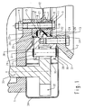
- Figure 1 shows an embodiment of the plain bearing according to the invention installed in a wind turbine in sectional view.
- the machine house 1 is by means of connecting screws 3 and Nuts 4 screwed to an inner ring 5.
- the inner ring 5 consists of a first ring part 6 and a second ring part 7, which are side by side in the axial direction are arranged and also by the connecting screws 3 and nuts 4th be held together.
- the connecting screws 3 are through corresponding through holes 8 and 9 in the ring parts 6 and 7 out.
- the through bores 9 in the second ring part 7 each have one larger diameter than the through holes 8 in the first ring part 6.
- each inserted bushings 10 which on a axial end have a circumferential collar 11 which is axially on the second Ring part 7 abuts.
- the other axial end of the socket 10 is supported axially on the first ring part 6, so that depending on the length of the bushings 10 an axial Gap 12 formed between the first ring part 6 and the second ring part 7 becomes.
- An outer ring 13 is fastened to the tower 2 by means of screws 14.
- the outer ring 13 has a circumferential radial projection 15 which is directed radially inwards is.
- the radial projection 15 has a perpendicular to the axial direction of the plain bearing oriented axial surface 16, one perpendicular to the radial direction of the plain bearing oriented radial surface 17 and a truncated cone surface 18, the central axis runs parallel to the axial direction of the plain bearing. All areas run rotationally symmetrical about the axis of the plain bearing.
- the radial projection 15 engages in an annular space 19 formed between the ring parts 6 and 7, which of the surfaces 16, 17 and 18 opposite and complementary to it trained areas 20, 21 and 22 is limited.
- Areas 20 and 22 are each set back a little so that recesses to accommodate Sliding segments 23 and 24 arise.
- the sliding segments 23 and 24 can For example, be glued to the surfaces 20 and 22 and are sliding Contact with the axial surface 16 and the truncated cone surface 18 Sliding pairing consisting of the sliding segments 23 and the axial surface 16 in essentially the weight of the nacelle 1 and the sliding pairing consisting of the sliding segments 24 and the truncated cone surface 18 ensures that Machine house 1 against tipping.
- the game in the two pairings depends depends on how strong the first ring part 6 and the second ring part 7 of the inner ring 5 with the help of the screws 3 are approximated. Because of this approximation the bushings 10 is limited, the game over the length of the bushings 10th be specified or set.
- the Outer ring 13 provided with a rack toothing.
- the Outer ring 13 has a U-shaped cross section, the U being radially outward is open.
- the two legs 27 and 28 are coaxial Provide through holes, into each of which a rack pin 29 is inserted is.
- the headstock bolts 29 are axially on both sides by a Seeger ring 30 secured, which engages in a groove 31 of the rack pin 29.
- the lower Seeger rings 30 can also be omitted if necessary, since the Triebstockbolzen 29 are already secured by their weight. In the Triebstockbolzen 29 engages a pinion 32 which is driven via a shaft 33 becomes.
- a plurality of pinions 32 can also be arranged distributed over the circumference his.
- the area of the drive rack and the pinion 32 or the pinion 32 is from a cover 34 which is attached to the nacelle 1 and each up to a small gap to the outer ring 13.
- an opening 35 is provided in the cover 34, through which the pinion 32 each engage in the rack teeth can.
- the cover 34 is used in the area of the rack teeth withheld lubricant and thus a loss of lubricant and prevent contamination of the surrounding machine parts.
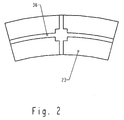
- FIG. 2 shows a plan view of a sliding segment 23.
- the sliding segments 24 are constructed accordingly and have only a slightly different shape.
- the Sliding segment 23 can consist of a plastic material and with or without Lubricant can be used. About the distribution of the lubricant and its The sliding segment 23 has to promote landfill in the area of the sliding surfaces Wells 36 on.
- the attachment of the sliding segment 23 can be done by gluing and / or screwing.
- the sliding segment 23 is on its Roughened back accordingly or has the sliding segment 23 corresponding Holes on.
- one could in principle also continuous sliding surface can be used.
- the handling is usually individual sliding segments 23, however, easier than that of a continuous one Sliding coating. This also applies with regard to the sliding segments 24.
- FIG 3 shows a detail of a second embodiment of the plain bearing according to the invention in a sectional view.
- the second Embodiment differs from that shown in Figure 1 regarding the components for the game setting.
- the section shown is therefore limited to the area in which these components are arranged.
- the two ring parts 6 and 7 of the inner ring are in turn by the Connection screws 3 and the nuts 4 screwed together. It is in second ring part 7, the connecting screw 3 through a threaded bushing 37 guided, which has an external thread 38, and in a threaded bore 39 in second ring part is screwed.
- the threaded bush 37 is through a Lock nut 40 secured against twisting.
- On the lock nut 40 is one Washer 41 is arranged, on which the connecting screw 3 rests axially.
- a game setting is by loosening the lock nut 40 and turning the threaded bush 37 possible.
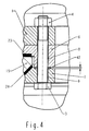
- FIG. 4 shows a detail of a third exemplary embodiment of the plain bearing according to the invention in a sectional view. It was the same Cutout selected, as in Figure 3.
- the peculiarity of the third Embodiment is that the game setting using Spacers 42 are used to establish the axial distance between the two Ring parts 6 and 7 of the inner ring 5 is set.
- the spacers 42 are arranged axially between the two ring parts 6 and 7 of the inner ring 5 and each take one of the connecting screws 3, with the help of which the two Ring parts 6 and 7 are screwed together.
- the third Exemplary embodiment no bushes 10 or threaded bushes 37 are provided, are the through bores 8 in the first ring part 6 and 9 in the second ring part 7 of the inner ring 5 each smooth and of the same diameter. To do that To change the play of the plain bearing, only the spacers 42 exchanged, the game by inserting thicker spacers 42 is increased and the game by inserting thinner spacers 42 is reduced.
Landscapes
- Engineering & Computer Science (AREA)
- General Engineering & Computer Science (AREA)
- Mechanical Engineering (AREA)
- Life Sciences & Earth Sciences (AREA)
- Sustainable Development (AREA)
- Sustainable Energy (AREA)
- Chemical & Material Sciences (AREA)
- Combustion & Propulsion (AREA)
- Sliding-Contact Bearings (AREA)
- Support Of The Bearing (AREA)
Applications Claiming Priority (2)
| Application Number | Priority Date | Filing Date | Title |
|---|---|---|---|
| DE20208133U | 2002-05-24 | ||
| DE20208133U DE20208133U1 (de) | 2002-05-24 | 2002-05-24 | Gleitlager zur axialen und radialen Lagerung |
Publications (3)
| Publication Number | Publication Date |
|---|---|
| EP1367273A2 true EP1367273A2 (fr) | 2003-12-03 |
| EP1367273A3 EP1367273A3 (fr) | 2006-04-19 |
| EP1367273B1 EP1367273B1 (fr) | 2008-07-09 |
Family
ID=28799100
Family Applications (1)
| Application Number | Title | Priority Date | Filing Date |
|---|---|---|---|
| EP03011683A Expired - Lifetime EP1367273B1 (fr) | 2002-05-24 | 2003-05-23 | Palier lisse pour charges radiales et axiales |
Country Status (3)
| Country | Link |
|---|---|
| EP (1) | EP1367273B1 (fr) |
| AT (1) | ATE400745T1 (fr) |
| DE (2) | DE20208133U1 (fr) |
Cited By (6)
| Publication number | Priority date | Publication date | Assignee | Title |
|---|---|---|---|---|
| WO2008077983A1 (fr) * | 2006-12-26 | 2008-07-03 | Gamesa Innovation & Technology, S.L. | Couronne à lacet à base coulissante pour aérogénérateurs |
| US8075190B1 (en) | 2010-09-16 | 2011-12-13 | Vestas Wind Systems A/S | Spherical plain bearing pocket arrangement and wind turbine having such a spherical plain bearing |
| US8172531B2 (en) | 2011-01-10 | 2012-05-08 | Vestas Wind Systems A/S | Plain bearing for a wind turbine blade and method of operating a wind turbine having such a plain bearing |
| CN102834611A (zh) * | 2010-04-14 | 2012-12-19 | 米巴·格来特来格有限公司 | 支承元件 |
| US8727728B2 (en) | 2010-09-16 | 2014-05-20 | Vestas Wind Systems A/S | Convertible bearing for a wind turbine and method for operating same |
| US8734105B2 (en) | 2010-09-16 | 2014-05-27 | Vestas Wind Systems A/S | Control system for a wind turbine and method of operating a wind turbine based on monitoring a bearing |
Families Citing this family (3)
| Publication number | Priority date | Publication date | Assignee | Title |
|---|---|---|---|---|
| DE102005051912A1 (de) * | 2005-10-29 | 2007-05-03 | Ab Skf | Anordnung |
| DE102006013275B4 (de) * | 2006-03-21 | 2008-07-03 | Air Fertigung-Technologie Gmbh | Lagersystem für Ringpropeller |
| WO2008148526A2 (fr) * | 2007-06-04 | 2008-12-11 | Suzlon Energy Gmbh | Ensemble palier pour éolienne |
Family Cites Families (13)
| Publication number | Priority date | Publication date | Assignee | Title |
|---|---|---|---|---|
| DE850365C (de) * | 1941-11-13 | 1952-09-25 | Leitz Ernst Gmbh | Schlag- und spielfreie Lagerung von Spindeln fuer Feinstbearbeitungs-maschinen mittels zweier Lagerstellen, von denen mindestens eine ein- und nachstellbar ist |
| US2719761A (en) * | 1952-10-28 | 1955-10-04 | Lapointe Machine Tool Co | Bearing structure for sliding machine carriage |
| US3434762A (en) * | 1963-07-11 | 1969-03-25 | Garrett Corp | Hydrodynamic shaft bearing |
| FR1424679A (fr) * | 1965-02-12 | 1966-01-14 | Licentia Gmbh | Palier mixte formant crapaudine et palier de guidage de machines électriques à arbre vertical |
| US3418027A (en) * | 1966-07-15 | 1968-12-24 | Atomic Energy Commission Usa | Rotary table |
| FR2175318A5 (fr) * | 1972-03-09 | 1973-10-19 | Skf Cie Applic Mecanique | |
| DE2827880B1 (de) * | 1978-06-24 | 1980-01-10 | Heidenhain Gmbh Dr Johannes | Gaslager fuer schnell rotierende Teile |
| JPS58174716A (ja) * | 1982-04-07 | 1983-10-13 | Mitsubishi Electric Corp | 回転電機の軸受装置 |
| US5286116A (en) * | 1992-08-31 | 1994-02-15 | Newport News Shipbuilding And Dry Dock Company | Bearing assembly |
| DE19917498A1 (de) * | 1999-04-17 | 2000-01-05 | Juergen Holzmueller | Wälzlager-Drehverbindung |
| DE19962978C1 (de) * | 1999-12-24 | 2001-08-30 | Aloys Wobben | Windenergieanlage mit einem turmgestützten Maschinenkopf |
| DE10043936C2 (de) * | 2000-09-07 | 2003-09-04 | Skf Gmbh | Gleitlager |
| DE10112517C1 (de) * | 2001-03-09 | 2002-04-25 | Atecs Mannesmann Ag | Großdrehlagerung mit Wälzkörpern |
-
2002
- 2002-05-24 DE DE20208133U patent/DE20208133U1/de not_active Expired - Lifetime
-
2003
- 2003-05-23 EP EP03011683A patent/EP1367273B1/fr not_active Expired - Lifetime
- 2003-05-23 DE DE50310097T patent/DE50310097D1/de not_active Expired - Fee Related
- 2003-05-23 AT AT03011683T patent/ATE400745T1/de not_active IP Right Cessation
Cited By (10)
| Publication number | Priority date | Publication date | Assignee | Title |
|---|---|---|---|---|
| WO2008077983A1 (fr) * | 2006-12-26 | 2008-07-03 | Gamesa Innovation & Technology, S.L. | Couronne à lacet à base coulissante pour aérogénérateurs |
| ES2326852A1 (es) * | 2006-12-26 | 2009-10-20 | GAMESA INNOVATION & TECHNOLOGY, S.L. | Corona de guiñada con base deslizante en aerogeneradores. |
| ES2326852B1 (es) * | 2006-12-26 | 2010-07-15 | GAMESA INNOVATION & TECHNOLOGY, S.L. | Corona de guiñada con base deslizante en aerogeneradores. |
| CN102834611A (zh) * | 2010-04-14 | 2012-12-19 | 米巴·格来特来格有限公司 | 支承元件 |
| CN102834611B (zh) * | 2010-04-14 | 2015-11-25 | 米巴·格来特来格有限公司 | 支承元件 |
| US8075190B1 (en) | 2010-09-16 | 2011-12-13 | Vestas Wind Systems A/S | Spherical plain bearing pocket arrangement and wind turbine having such a spherical plain bearing |
| US8079761B1 (en) | 2010-09-16 | 2011-12-20 | Vestas Wind Systems A/S | Cylindrical plain bearing pocket arrangement and wind turbine having such a cylindrical plain bearing |
| US8727728B2 (en) | 2010-09-16 | 2014-05-20 | Vestas Wind Systems A/S | Convertible bearing for a wind turbine and method for operating same |
| US8734105B2 (en) | 2010-09-16 | 2014-05-27 | Vestas Wind Systems A/S | Control system for a wind turbine and method of operating a wind turbine based on monitoring a bearing |
| US8172531B2 (en) | 2011-01-10 | 2012-05-08 | Vestas Wind Systems A/S | Plain bearing for a wind turbine blade and method of operating a wind turbine having such a plain bearing |
Also Published As
| Publication number | Publication date |
|---|---|
| EP1367273A3 (fr) | 2006-04-19 |
| EP1367273B1 (fr) | 2008-07-09 |
| DE50310097D1 (de) | 2008-08-21 |
| DE20208133U1 (de) | 2003-10-02 |
| ATE400745T1 (de) | 2008-07-15 |
Similar Documents
| Publication | Publication Date | Title |
|---|---|---|
| EP1975405B1 (fr) | Raccordement des éléments d'une installation d'énergie éolienne, utilization et procédé | |
| EP2812568B1 (fr) | Ensemble palier à roulement destiné à supporter des pièces d'une éolienne, ainsi qu'éolienne pourvue d'un palier de pale ainsi réalisé | |
| DE102005026141C5 (de) | Windkraftanlage mit einer Lagereinheit für ein langgestrecktes Rotorblatt | |
| EP2676042B1 (fr) | Palier à roulements axiaux-radiaux, en particulier pour le support de pales de rotor sur une éolienne | |
| EP3550140B1 (fr) | Support de machine pour éolienne | |
| WO2001048376A2 (fr) | Palier a glissement et eolienne equipee de ce dernier | |
| WO2018189143A1 (fr) | Ensemble palier servant à supporter une pale de rotor d'une éolienne | |
| EP1365147A2 (fr) | Paliers à coulisse pour éoliennes | |
| WO2010037372A1 (fr) | Liaison rotative, notamment palier à roulement à contact oblique à plusieurs rangées doté de trois bagues de roulement concentriques pour une éolienne, et éolienne dotée de cette iiaison rotative | |
| EP3728835A1 (fr) | Éolienne, système rotor et procédé d'utilisation d'une éolienne | |
| EP1367273B1 (fr) | Palier lisse pour charges radiales et axiales | |
| DE10043936A1 (de) | Gleitlager | |
| DE69712577T2 (de) | Verfahren zum Zusammenbau eines Planetenuntersetzungsgetriebes und Planetenuntersetzungsgetriebe | |
| EP4062078B1 (fr) | Agencement de palier et procédé de fabrication dudit type d'agencement de palier | |
| WO2006039899A1 (fr) | Cage a tourillon, notamment pour roulements a rouleaux radiaux ou axiaux de grande taille | |
| EP3384183B1 (fr) | Porte-satellites pour étage d'engrenage d'un engrenage planétaire et procédé de précontrainte | |
| EP3794228A1 (fr) | Système de liaison pivotante pour une pale de rotor d'une éolienne | |
| EP1367274A2 (fr) | Palier à contact lisse avec engrenage intégré | |
| DE10316005A1 (de) | Verfahren zur Einstellung des Spiels oder der Vorspannung eines Lagers | |
| EP3844392B1 (fr) | Ensemble de paliers pour une eolienne et eolienne | |
| DE102004029581A1 (de) | Zentralgelenk für einen Dreieckslenker von Kraftfahrzeugen | |
| DE102024104793B4 (de) | Hydrodynamische Rotorwellengleitlagerung für eine Rotorwelle einer Windkraftanlage | |
| LU103210B1 (de) | Nabenanordnung für eine Windenergieanlage | |
| EP1365148A2 (fr) | Système de lubrification pour le vireur azimutale d'une éolienne | |
| EP3685059A1 (fr) | Roulement à rouleaux à contact oblique |
Legal Events
| Date | Code | Title | Description |
|---|---|---|---|
| PUAI | Public reference made under article 153(3) epc to a published international application that has entered the european phase |
Free format text: ORIGINAL CODE: 0009012 |
|
| AK | Designated contracting states |
Kind code of ref document: A2 Designated state(s): AT BE BG CH CY CZ DE DK EE ES FI FR GB GR HU IE IT LI LU MC NL PT RO SE SI SK TR |
|
| AX | Request for extension of the european patent |
Extension state: AL LT LV MK |
|
| PUAL | Search report despatched |
Free format text: ORIGINAL CODE: 0009013 |
|
| AK | Designated contracting states |
Kind code of ref document: A3 Designated state(s): AT BE BG CH CY CZ DE DK EE ES FI FR GB GR HU IE IT LI LU MC NL PT RO SE SI SK TR |
|
| AX | Request for extension of the european patent |
Extension state: AL LT LV MK |
|
| 17P | Request for examination filed |
Effective date: 20060511 |
|
| AKX | Designation fees paid |
Designated state(s): AT BE BG CH CY CZ DE DK EE ES FI FR GB GR HU IE IT LI LU MC NL PT RO SE SI SK TR |
|
| GRAP | Despatch of communication of intention to grant a patent |
Free format text: ORIGINAL CODE: EPIDOSNIGR1 |
|
| GRAS | Grant fee paid |
Free format text: ORIGINAL CODE: EPIDOSNIGR3 |
|
| GRAA | (expected) grant |
Free format text: ORIGINAL CODE: 0009210 |
|
| AK | Designated contracting states |
Kind code of ref document: B1 Designated state(s): AT BE BG CH CY CZ DE DK EE ES FI FR GB GR HU IE IT LI LU MC NL PT RO SE SI SK TR |
|
| REG | Reference to a national code |
Ref country code: GB Ref legal event code: FG4D Free format text: NOT ENGLISH |
|
| REG | Reference to a national code |
Ref country code: CH Ref legal event code: EP |
|
| REF | Corresponds to: |
Ref document number: 50310097 Country of ref document: DE Date of ref document: 20080821 Kind code of ref document: P |
|
| REG | Reference to a national code |
Ref country code: IE Ref legal event code: FG4D Free format text: LANGUAGE OF EP DOCUMENT: GERMAN |
|
| NLV1 | Nl: lapsed or annulled due to failure to fulfill the requirements of art. 29p and 29m of the patents act | ||
| PG25 | Lapsed in a contracting state [announced via postgrant information from national office to epo] |
Ref country code: NL Free format text: LAPSE BECAUSE OF FAILURE TO SUBMIT A TRANSLATION OF THE DESCRIPTION OR TO PAY THE FEE WITHIN THE PRESCRIBED TIME-LIMIT Effective date: 20080709 Ref country code: PT Free format text: LAPSE BECAUSE OF FAILURE TO SUBMIT A TRANSLATION OF THE DESCRIPTION OR TO PAY THE FEE WITHIN THE PRESCRIBED TIME-LIMIT Effective date: 20081209 Ref country code: ES Free format text: LAPSE BECAUSE OF FAILURE TO SUBMIT A TRANSLATION OF THE DESCRIPTION OR TO PAY THE FEE WITHIN THE PRESCRIBED TIME-LIMIT Effective date: 20081020 |
|
| PG25 | Lapsed in a contracting state [announced via postgrant information from national office to epo] |
Ref country code: SI Free format text: LAPSE BECAUSE OF FAILURE TO SUBMIT A TRANSLATION OF THE DESCRIPTION OR TO PAY THE FEE WITHIN THE PRESCRIBED TIME-LIMIT Effective date: 20080709 Ref country code: BG Free format text: LAPSE BECAUSE OF FAILURE TO SUBMIT A TRANSLATION OF THE DESCRIPTION OR TO PAY THE FEE WITHIN THE PRESCRIBED TIME-LIMIT Effective date: 20081009 Ref country code: FI Free format text: LAPSE BECAUSE OF FAILURE TO SUBMIT A TRANSLATION OF THE DESCRIPTION OR TO PAY THE FEE WITHIN THE PRESCRIBED TIME-LIMIT Effective date: 20080709 |
|
| REG | Reference to a national code |
Ref country code: IE Ref legal event code: FD4D |
|
| PG25 | Lapsed in a contracting state [announced via postgrant information from national office to epo] |
Ref country code: DK Free format text: LAPSE BECAUSE OF FAILURE TO SUBMIT A TRANSLATION OF THE DESCRIPTION OR TO PAY THE FEE WITHIN THE PRESCRIBED TIME-LIMIT Effective date: 20080709 Ref country code: IE Free format text: LAPSE BECAUSE OF FAILURE TO SUBMIT A TRANSLATION OF THE DESCRIPTION OR TO PAY THE FEE WITHIN THE PRESCRIBED TIME-LIMIT Effective date: 20080709 Ref country code: EE Free format text: LAPSE BECAUSE OF FAILURE TO SUBMIT A TRANSLATION OF THE DESCRIPTION OR TO PAY THE FEE WITHIN THE PRESCRIBED TIME-LIMIT Effective date: 20080709 |
|
| PLBE | No opposition filed within time limit |
Free format text: ORIGINAL CODE: 0009261 |
|
| STAA | Information on the status of an ep patent application or granted ep patent |
Free format text: STATUS: NO OPPOSITION FILED WITHIN TIME LIMIT |
|
| PG25 | Lapsed in a contracting state [announced via postgrant information from national office to epo] |
Ref country code: RO Free format text: LAPSE BECAUSE OF FAILURE TO SUBMIT A TRANSLATION OF THE DESCRIPTION OR TO PAY THE FEE WITHIN THE PRESCRIBED TIME-LIMIT Effective date: 20080709 Ref country code: CZ Free format text: LAPSE BECAUSE OF FAILURE TO SUBMIT A TRANSLATION OF THE DESCRIPTION OR TO PAY THE FEE WITHIN THE PRESCRIBED TIME-LIMIT Effective date: 20080709 Ref country code: SK Free format text: LAPSE BECAUSE OF FAILURE TO SUBMIT A TRANSLATION OF THE DESCRIPTION OR TO PAY THE FEE WITHIN THE PRESCRIBED TIME-LIMIT Effective date: 20080709 |
|
| 26N | No opposition filed |
Effective date: 20090414 |
|
| PG25 | Lapsed in a contracting state [announced via postgrant information from national office to epo] |
Ref country code: IT Free format text: LAPSE BECAUSE OF FAILURE TO SUBMIT A TRANSLATION OF THE DESCRIPTION OR TO PAY THE FEE WITHIN THE PRESCRIBED TIME-LIMIT Effective date: 20080709 |
|
| PGFP | Annual fee paid to national office [announced via postgrant information from national office to epo] |
Ref country code: DE Payment date: 20090528 Year of fee payment: 7 |
|
| BERE | Be: lapsed |
Owner name: A.B. SKF Effective date: 20090531 |
|
| PG25 | Lapsed in a contracting state [announced via postgrant information from national office to epo] |
Ref country code: MC Free format text: LAPSE BECAUSE OF NON-PAYMENT OF DUE FEES Effective date: 20090531 |
|
| REG | Reference to a national code |
Ref country code: CH Ref legal event code: PL |
|
| GBPC | Gb: european patent ceased through non-payment of renewal fee |
Effective date: 20090523 |
|
| PG25 | Lapsed in a contracting state [announced via postgrant information from national office to epo] |
Ref country code: LI Free format text: LAPSE BECAUSE OF NON-PAYMENT OF DUE FEES Effective date: 20090531 Ref country code: CH Free format text: LAPSE BECAUSE OF NON-PAYMENT OF DUE FEES Effective date: 20090531 Ref country code: SE Free format text: LAPSE BECAUSE OF FAILURE TO SUBMIT A TRANSLATION OF THE DESCRIPTION OR TO PAY THE FEE WITHIN THE PRESCRIBED TIME-LIMIT Effective date: 20081009 |
|
| REG | Reference to a national code |
Ref country code: FR Ref legal event code: ST Effective date: 20100129 |
|
| PG25 | Lapsed in a contracting state [announced via postgrant information from national office to epo] |
Ref country code: FR Free format text: LAPSE BECAUSE OF NON-PAYMENT OF DUE FEES Effective date: 20090602 |
|
| PG25 | Lapsed in a contracting state [announced via postgrant information from national office to epo] |
Ref country code: GB Free format text: LAPSE BECAUSE OF NON-PAYMENT OF DUE FEES Effective date: 20090523 |
|
| PG25 | Lapsed in a contracting state [announced via postgrant information from national office to epo] |
Ref country code: BE Free format text: LAPSE BECAUSE OF NON-PAYMENT OF DUE FEES Effective date: 20090531 |
|
| PG25 | Lapsed in a contracting state [announced via postgrant information from national office to epo] |
Ref country code: AT Free format text: LAPSE BECAUSE OF NON-PAYMENT OF DUE FEES Effective date: 20090523 |
|
| PG25 | Lapsed in a contracting state [announced via postgrant information from national office to epo] |
Ref country code: GR Free format text: LAPSE BECAUSE OF FAILURE TO SUBMIT A TRANSLATION OF THE DESCRIPTION OR TO PAY THE FEE WITHIN THE PRESCRIBED TIME-LIMIT Effective date: 20081010 |
|
| PG25 | Lapsed in a contracting state [announced via postgrant information from national office to epo] |
Ref country code: LU Free format text: LAPSE BECAUSE OF NON-PAYMENT OF DUE FEES Effective date: 20090523 Ref country code: DE Free format text: LAPSE BECAUSE OF NON-PAYMENT OF DUE FEES Effective date: 20101201 |
|
| PG25 | Lapsed in a contracting state [announced via postgrant information from national office to epo] |
Ref country code: HU Free format text: LAPSE BECAUSE OF FAILURE TO SUBMIT A TRANSLATION OF THE DESCRIPTION OR TO PAY THE FEE WITHIN THE PRESCRIBED TIME-LIMIT Effective date: 20090110 |
|
| PG25 | Lapsed in a contracting state [announced via postgrant information from national office to epo] |
Ref country code: TR Free format text: LAPSE BECAUSE OF FAILURE TO SUBMIT A TRANSLATION OF THE DESCRIPTION OR TO PAY THE FEE WITHIN THE PRESCRIBED TIME-LIMIT Effective date: 20080709 |
|
| PG25 | Lapsed in a contracting state [announced via postgrant information from national office to epo] |
Ref country code: CY Free format text: LAPSE BECAUSE OF FAILURE TO SUBMIT A TRANSLATION OF THE DESCRIPTION OR TO PAY THE FEE WITHIN THE PRESCRIBED TIME-LIMIT Effective date: 20080709 |