EP1367302A2 - Dispositif d'étanchéité - Google Patents
Dispositif d'étanchéité Download PDFInfo
- Publication number
- EP1367302A2 EP1367302A2 EP03010600A EP03010600A EP1367302A2 EP 1367302 A2 EP1367302 A2 EP 1367302A2 EP 03010600 A EP03010600 A EP 03010600A EP 03010600 A EP03010600 A EP 03010600A EP 1367302 A2 EP1367302 A2 EP 1367302A2
- Authority
- EP
- European Patent Office
- Prior art keywords
- sealing arrangement
- opening
- sealing
- ring
- barrier fluid
- Prior art date
- Legal status (The legal status is an assumption and is not a legal conclusion. Google has not performed a legal analysis and makes no representation as to the accuracy of the status listed.)
- Withdrawn
Links
- 238000007789 sealing Methods 0.000 title claims description 65
- 239000012530 fluid Substances 0.000 claims abstract description 31
- 239000011248 coating agent Substances 0.000 claims abstract description 27
- 238000004140 cleaning Methods 0.000 claims description 49
- 238000003780 insertion Methods 0.000 claims description 28
- 230000037431 insertion Effects 0.000 claims description 28
- 230000004888 barrier function Effects 0.000 claims description 19
- 230000002093 peripheral effect Effects 0.000 claims description 11
- 239000000463 material Substances 0.000 abstract description 4
- 238000000576 coating method Methods 0.000 abstract description 3
- 230000000903 blocking effect Effects 0.000 abstract 1
- 239000007921 spray Substances 0.000 description 28
- 239000007788 liquid Substances 0.000 description 12
- 239000003973 paint Substances 0.000 description 8
- 229920001971 elastomer Polymers 0.000 description 7
- 230000000694 effects Effects 0.000 description 4
- -1 polyethylene Polymers 0.000 description 4
- 238000000034 method Methods 0.000 description 3
- 229930040373 Paraformaldehyde Natural products 0.000 description 2
- 239000004952 Polyamide Substances 0.000 description 2
- 239000004698 Polyethylene Substances 0.000 description 2
- 239000004743 Polypropylene Substances 0.000 description 2
- 238000011109 contamination Methods 0.000 description 2
- 238000011010 flushing procedure Methods 0.000 description 2
- 229920003229 poly(methyl methacrylate) Polymers 0.000 description 2
- 229920002647 polyamide Polymers 0.000 description 2
- 229920000573 polyethylene Polymers 0.000 description 2
- 239000004926 polymethyl methacrylate Substances 0.000 description 2
- 229920006324 polyoxymethylene Polymers 0.000 description 2
- 229920001155 polypropylene Polymers 0.000 description 2
- 229920001343 polytetrafluoroethylene Polymers 0.000 description 2
- 239000004810 polytetrafluoroethylene Substances 0.000 description 2
- 229920002635 polyurethane Polymers 0.000 description 2
- 239000004814 polyurethane Substances 0.000 description 2
- 230000002441 reversible effect Effects 0.000 description 2
- 229910000838 Al alloy Inorganic materials 0.000 description 1
- 239000004793 Polystyrene Substances 0.000 description 1
- 230000001154 acute effect Effects 0.000 description 1
- AZDRQVAHHNSJOQ-UHFFFAOYSA-N alumane Chemical group [AlH3] AZDRQVAHHNSJOQ-UHFFFAOYSA-N 0.000 description 1
- XAGFODPZIPBFFR-UHFFFAOYSA-N aluminium Chemical compound [Al] XAGFODPZIPBFFR-UHFFFAOYSA-N 0.000 description 1
- 229910052782 aluminium Inorganic materials 0.000 description 1
- 238000007664 blowing Methods 0.000 description 1
- 238000011161 development Methods 0.000 description 1
- 230000018109 developmental process Effects 0.000 description 1
- 238000010586 diagram Methods 0.000 description 1
- 238000006073 displacement reaction Methods 0.000 description 1
- 238000001035 drying Methods 0.000 description 1
- 238000004519 manufacturing process Methods 0.000 description 1
- 239000003595 mist Substances 0.000 description 1
- 238000012986 modification Methods 0.000 description 1
- 230000004048 modification Effects 0.000 description 1
- 238000010422 painting Methods 0.000 description 1
- 239000002245 particle Substances 0.000 description 1
- 230000035515 penetration Effects 0.000 description 1
- 239000004033 plastic Substances 0.000 description 1
- 229920003023 plastic Polymers 0.000 description 1
- 239000004417 polycarbonate Substances 0.000 description 1
- 229920000515 polycarbonate Polymers 0.000 description 1
- 239000004800 polyvinyl chloride Substances 0.000 description 1
- 230000036316 preload Effects 0.000 description 1
- 238000005086 pumping Methods 0.000 description 1
- 238000005507 spraying Methods 0.000 description 1
Images

Classifications
-
- F—MECHANICAL ENGINEERING; LIGHTING; HEATING; WEAPONS; BLASTING
- F16—ENGINEERING ELEMENTS AND UNITS; GENERAL MEASURES FOR PRODUCING AND MAINTAINING EFFECTIVE FUNCTIONING OF MACHINES OR INSTALLATIONS; THERMAL INSULATION IN GENERAL
- F16J—PISTONS; CYLINDERS; SEALINGS
- F16J15/00—Sealings
- F16J15/16—Sealings between relatively-moving surfaces
- F16J15/40—Sealings between relatively-moving surfaces by means of fluid
-
- B—PERFORMING OPERATIONS; TRANSPORTING
- B05—SPRAYING OR ATOMISING IN GENERAL; APPLYING FLUENT MATERIALS TO SURFACES, IN GENERAL
- B05B—SPRAYING APPARATUS; ATOMISING APPARATUS; NOZZLES
- B05B15/00—Details of spraying plant or spraying apparatus not otherwise provided for; Accessories
- B05B15/50—Arrangements for cleaning; Arrangements for preventing deposits, drying-out or blockage; Arrangements for detecting improper discharge caused by the presence of foreign matter
- B05B15/55—Arrangements for cleaning; Arrangements for preventing deposits, drying-out or blockage; Arrangements for detecting improper discharge caused by the presence of foreign matter using cleaning fluids
- B05B15/555—Arrangements for cleaning; Arrangements for preventing deposits, drying-out or blockage; Arrangements for detecting improper discharge caused by the presence of foreign matter using cleaning fluids discharged by cleaning nozzles
Definitions
- the invention relates to a sealing arrangement for contactless Sealing an opening, in particular for sealing an Gap between a peripheral edge of an insertion opening Cleaning device and one inserted into the insertion opening Coating agent application device, according to the generic term of claim 1.
- Spray devices such as spray guns for atomizing or atomizing of color, such as for coating vehicle bodies or other workpieces must be used, especially in the area of the paint nozzles and any existing air nozzles in regular Intervals cleaned, d. H. of which through paint mist and Drops of paint that are created on the self-coating can be removed.
- a cleaning device is known from EP 0 333 040 B1, in which is a coating agent application device, such as a spray gun, with a cleaning liquid sprayed and thereby cleaned.
- the coating agent application device is from above through an insertion opening introduced into the known cleaning device, one conventional rubber seal seals the insertion opening to to prevent the cleaning liquid from escaping.
- a disadvantage of the sealing of the insertion opening by a rubber seal is the fact that it's through touch contact between the rubber seal and the coating agent application device to wear of the rubber seal Material removal and a loss of preload comes. The consequences this wear is a waning sealing effect until failure, an uncontrolled leak of cleaning fluid and / or a thinning of dirt and thus contamination of the coating agent application device and the Cleaning device. When the coating agent application device is wetted due to an insufficient sealing effect There is a risk of the rubber seal dripping later from cleaning liquid to the paint to be painted Surface.
- Another disadvantage of sealing with a rubber seal consists in the possibility of stripping paint on the rubber seal, whereby the paint contamination is not areas of the coating agent application device to be cleaned collects and onto the surface to be painted can fall.
- the invention is therefore based on the object in a sealing arrangement of the considered type for non-contact sealing an opening to improve the sealing effect.
- the invention encompasses the general technical teaching, through a suitable nozzle arrangement a sealing air flow that is as uniform as possible to seal an opening.
- the nozzle for the Delivery of the sealing air flow in the circumferential direction at least above extends a large part of the peripheral edge of the opening to be sealed. As a result, a uniform sealing air flow over reached the opening to be sealed without gaps in the seal.
- a preferred embodiment of the invention extends the nozzle for the discharge of the sealing air flow in the circumferential direction over the entire perimeter of the opening, however it is possible that the nozzle is only on one side of the to be sealed Opening extends over a large part of the peripheral edge.
- Another fluid is used instead of a compressed air flow can be, preferably gaseous or liquid Use fluids for sealing.
- Sealing arrangement according to the invention can the supply of Barrier fluids (e.g. compressed air) at a central feed point take place, the channel circulating in the ring the barrier fluid evenly distributed over the circumferential edge of the opening.
- the barrier fluid is preferably fed into the channel via a feed hole, which is preferably a tangential Directional component has.
- a feed hole which is preferably a tangential Directional component has.
- This has the advantage that the supplied barrier fluid is even in the channel distributed, whereby the barrier fluid flow discharged through the nozzle evenly distributed over the circumference of the insertion opening.
- the barrier fluid is arranged in a plurality of feed bores, which each open at an acute angle into the channel.
- the ring with the channel for the supply of the barrier fluid exists preferably of at least two parts, which in the assembled state are arranged one above the other, whereby the assembly of the invention Sealing arrangement is significantly facilitated.
- sealing arrangement points the ring with the channel for the feed of the barrier fluid and the nozzle on its outside one over the Circumferential groove around the ring to mount the ring can. This groove engages in the assembled state of the invention Sealing arrangement of the inner edge of a lid, which covers the insertion opening on its peripheral edge.
- This circumferential groove of the ring preferably has on its groove base an outer diameter that is smaller than the inner diameter of the lid.
- the insertion opening of the cleaning device preferably on the outer contour of the coating agent application device adjusted so that in the imported state of the coating agent application device preferably constant gap of the insertion opening remains.
- the sealing arrangement As a material for the sealing arrangement according to the invention and the ring is particularly suitable for aluminum or an aluminum alloy. However, it is also possible to use the sealing arrangement or to manufacture the ring from plastic, such as for example polyethylene (PE), polytetrafluoroethylene (PTFE), Polypropylene (PP), polyamide (PA), polyurethane (PUR), polymethyl methacrylate (PMMA), polyvinyl chloride (PVC), polycarbonate (PC), Polyoxymethylene (POM), polystyrene (PS) or combinations of these Materials.
- plastic such as for example polyethylene (PE), polytetrafluoroethylene (PTFE), Polypropylene (PP), polyamide (PA), polyurethane (PUR), polymethyl methacrylate (PMMA), polyvinyl chloride (PVC), polycarbonate (PC), Polyoxymethylene (POM), polystyrene (PS) or combinations of these Materials.
- PE polyethylene
- PTFE polytetrafluoroethylene
- PP
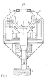
- FIG. 1 shows largely schematically a cleaning device 1 for cleaning a spray gun, the spray gun not shown for simplicity is.
- the cleaning device 1 has a container one rotationally symmetrical about a generally vertical axis trained interior 3.
- the interior has on its top 3 concentrically to its axis an insertion opening 4, through which is the part of the spray gun to be cleaned in the interior can be used.
- the space between the in the cleaning device 1 spray gun used and the edge of the insertion opening 4 can be sealed by a sealing device 5, which prevents the escape of cleaning fluid and paint residues and shown in detail in Figures 2 and 3a and 3b is.
- nozzle arrangement 6 Inside the interior 3 is one about a transverse to the container axis extending axis rotatable nozzle assembly 6 attached.
- the nozzle arrangement 6 is supported by means of two shafts 7, which the feed lines for one to be fed to the nozzle arrangement Containing cleaning liquid and in two bushings 12 sealed against the outside are rotatably mounted. With the Ends of the shafts 7 are connected via a rotary seal 13.
- the inflow of cleaning fluid is through valves 9 controlled, preferably by solenoid valves, the automatic Facilitate operations.
- the nozzle arrangement 6 contains several nozzles 8 or other nozzle openings, through which the cleaning liquid to the cleaning area of the spray gun is sprayed.
- she consists essentially of a generally U-shaped or approximate semicircular curved bracket that runs across the two Arm leg extending axis of the shafts 7 pivotally mounted is and is arranged such that the spray gun with their area to be cleaned in the space between the two arm legs protrudes.
- the bracket is at least about 180 ° pivotable, so it can around the end projecting into the interior 3 Spray gun from the front visible in the drawing to be pivoted to the back so that during the Swivel movement on all relevant areas of the spray gun sprayed all over the place.
- the nozzle arrangement 6 is coupled to one of the shafts 7 pneumatically or electrically controlled drive device 16 moves, which is connected to an adjusting device is.
- the rotary movement takes place around certain, previously set Angular amounts in both directions of rotation on the drive device 16 are reversible.
- On the other shaft 7 is a position encoder 14 attached, the information about a position sensor 15 outputs the current position of the nozzle assembly 6. To reverse the drive and report back to the basic stirrup position can two proximity sensors on the position sensor 15 to be appropriate.
- the bracket is in one lateral basic position (not shown). For example at this position can flush liquid or flush fluid from the inside the spray gun with internal flushing into the cleaning device 1 can be emptied into it.
- the internal flushing of spray guns is known per se, but here is the result Advantage of the problem-free disposal of the rinsing liquid.
- the used cleaning fluid draining from the spray gun is through a funnel-shaped part 10 of the interior 3 collected and over the center of the funnel-shaped part caught in a collecting container 20.
- a collecting container 20 Preferably during of the spraying process the cleaning liquid from the Drain interior 3.
- an automatically controllable valve 19 is available is, the collection container 20 with the valve closed be emptied into a drain line by compressed air.
- the emptying can instead also by vacuum, i.e. by suction or pumping out.
- the emptying can be timed are and preferably take place after the cleaning process has ended, possibly at a time when the cleaned Spray device is already in operation again.
- the invention is particularly well suited for the fully automatic controlled cleaning of a painting robot or other Program-controlled automatic spray gun.
- the cleaning device be appropriately attached to the robot itself.
- the device is the part of the spray gun to be cleaned from the robot from a defined entry position (expediently at slow speed) vertically downwards through the insertion opening 4 into the cleaning device 1.
- sensors it can be reported that the spray gun is in the correct position.
- the spray gun is then according to a predetermined Flow diagram with simultaneous movement of the swivel bracket sprayed with cleaning liquid.
- the Spray gun dried with compressed air after cleaning by separately mounted on the wall of the interior, to a (Not shown) line connected air nozzles 18 on the Spray head of the spray gun is blown.
- the air vents can also be arranged on the pivotable nozzle arrangement 6. During the cleaning process and the drying process any air holes (openings for horn and atomizing air) by blowing out the outside of the spray gun of air before the penetration of cleaning fluid and Debris protected.
- the sealing device 5 is preferably designed such that that inevitable radial and axial positional deviations between the spray gun and the container of the cleaning device 1 are compensable.
- the free inside diameter of the sealing device 5 is therefore preferably larger than the outer diameter the spray gun, even in the event of radial incorrect positioning the spray gun a collision between the spray gun and to prevent the sealing device 5.
- the sealing device 5 shown in FIGS. 2 and 3a consists essentially of an aluminum ring with a circumferential channel 21 arranged for supply in the interior of the ring of compressed air.
- the ring has an inlet opening at one point for compressed air that opens into channel 21 and can be connected to a conventional compressed air supply line can.
- the channel 21 opens into a gap 22 which over runs around the entire circumference of the ring and forms a nozzle.
- the compressed air therefore escapes from the channel 21 through the gap 22 and sweeps radially inward over the insertion opening 4, whereby an escape of cleaning fluid from the cleaning device 1 is prevented.
- the one shown in Fig. 3a The exemplary embodiment is the exit direction of the sealing air flow exactly radial and has no axial component.
- FIG. 3b shows an alternative embodiment of a Sealing arrangement 5 'according to the invention with a channel 21' and one arranged on the inside of the sealing arrangement 5 ', circumferential gap 22 ', which forms a nozzle.
- the peculiarity of this embodiment is that the gap 22 'is so is shaped that the emerging sealing air flow is an axial component has, which with respect to the cleaning device 1 is directed inside. This also prevents Cleaning liquid or paint residues from the cleaning device 1 can exit.
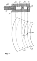
- the ring has a circumferential nozzle 25 in on its inside Form a slot on the inside of the ring into a channel 26 opens for the supply of compressed air.
- the nozzle 25 is here aligned so that the compressed air emerging from the nozzle 25 an axial component inside the cleaning device 1 has. This improves the sealing effect because the coating agent particles into the interior of the cleaning device 1 be pressed back.
- the ring has a groove on its radially outer side 27 that runs around the entire circumference of the ring and one Assembly of the ring on the cleaning device 1 enables.
- the cleaning device 1 has a cover 28, which rests on the insertion opening of the cleaning device 1 and received with its inner peripheral edge in the groove 27 of the ring which will fix the ring.
- the outside diameter of the ring at the bottom of the groove 27 is essential here smaller than the inside diameter of the cover 28, so that between there is a radial clearance fit for the cover 28 and the ring, which is a radial displacement of the ring relative to that Lid 28 allows.
- the ring can move sideways dodge if the coating agent application device at Insertion into the insertion opening due to incorrect positioning abuts the ring. This will advantageously damage of the coating agent application device or seal arrangement according to the invention prevented.
- the groove 27 is connected to the channel 26 via a feed bore 30, where the feed bore 30 is a tangential directional component has, so that the blown into the channel 26 Compressed air distributed as evenly as possible over the circumference of the ring, which is advantageous due to a uniform blow-out pressure the nozzle 25 leads.
Landscapes
- Engineering & Computer Science (AREA)
- General Engineering & Computer Science (AREA)
- Mechanical Engineering (AREA)
- Details Or Accessories Of Spraying Plant Or Apparatus (AREA)
- Nozzles (AREA)
- Coating Apparatus (AREA)
Applications Claiming Priority (4)
| Application Number | Priority Date | Filing Date | Title |
|---|---|---|---|
| DE10223500 | 2002-05-27 | ||
| DE10223500 | 2002-05-27 | ||
| DE10240073 | 2002-08-30 | ||
| DE10240073A DE10240073A1 (de) | 2002-05-27 | 2002-08-30 | Dichtungsanordnung |
Publications (2)
| Publication Number | Publication Date |
|---|---|
| EP1367302A2 true EP1367302A2 (fr) | 2003-12-03 |
| EP1367302A3 EP1367302A3 (fr) | 2004-04-14 |
Family
ID=29421514
Family Applications (1)
| Application Number | Title | Priority Date | Filing Date |
|---|---|---|---|
| EP03010600A Withdrawn EP1367302A3 (fr) | 2002-05-27 | 2003-05-12 | Dispositif d'étanchéité |
Country Status (1)
| Country | Link |
|---|---|
| EP (1) | EP1367302A3 (fr) |
Cited By (8)
| Publication number | Priority date | Publication date | Assignee | Title |
|---|---|---|---|---|
| EP1671706A3 (fr) * | 2004-12-20 | 2006-07-19 | Dürr Systems GmbH | Procédé et appareil de nettoyage des appareils de pulvérisation |
| EP1764157A2 (fr) | 2005-09-15 | 2007-03-21 | Dürr Systems GmbH | Elément d'un pulvérisateur rotatif |
| US7908994B2 (en) | 2005-10-21 | 2011-03-22 | Duerr Systems, Inc. | Automatically steered coating machine also a container for the coating material |
| US8418647B2 (en) | 2005-10-21 | 2013-04-16 | Dürr Systems Inc. | Procedure and piston type metering devices for the metered material supply for a coating device |
| US8430340B2 (en) | 2005-04-05 | 2013-04-30 | Dürr Systems Inc. | Rotary atomizer component |
| DE102012024040A1 (de) * | 2012-12-08 | 2014-06-26 | Volkswagen Aktiengesellschaft | Reinigungsvorrichtung für ein Lackierwerkzeug |
| DE102014006647A1 (de) | 2014-05-07 | 2015-11-12 | Dürr Systems GmbH | Reinigungsgerät für einen Zerstäuber und zugehöriges Betriebsverfahren |
| DE102018130809A1 (de) | 2018-12-04 | 2020-06-04 | Dürr Systems Ag | Auffangvorrichtung für Spülmedien eines Zerstäubers |
Citations (2)
| Publication number | Priority date | Publication date | Assignee | Title |
|---|---|---|---|---|
| EP0333040B1 (fr) | 1988-03-16 | 1994-01-05 | Dürr GmbH | Procédé et appareil de nettoyage des appareils de pulvérisation |
| US5693150A (en) * | 1996-05-03 | 1997-12-02 | Aeg Automation Systems Corporation | Automatic paint gun cleaner |
Family Cites Families (1)
| Publication number | Priority date | Publication date | Assignee | Title |
|---|---|---|---|---|
| GB636301A (en) * | 1948-03-08 | 1950-04-26 | Brown Brothers & Co Ltd | Fluid seal |
-
2003
- 2003-05-12 EP EP03010600A patent/EP1367302A3/fr not_active Withdrawn
Patent Citations (2)
| Publication number | Priority date | Publication date | Assignee | Title |
|---|---|---|---|---|
| EP0333040B1 (fr) | 1988-03-16 | 1994-01-05 | Dürr GmbH | Procédé et appareil de nettoyage des appareils de pulvérisation |
| US5693150A (en) * | 1996-05-03 | 1997-12-02 | Aeg Automation Systems Corporation | Automatic paint gun cleaner |
Cited By (13)
| Publication number | Priority date | Publication date | Assignee | Title |
|---|---|---|---|---|
| EP1671706A3 (fr) * | 2004-12-20 | 2006-07-19 | Dürr Systems GmbH | Procédé et appareil de nettoyage des appareils de pulvérisation |
| US7721745B2 (en) | 2004-12-20 | 2010-05-25 | Duerr Systems, Inc. | Method and cleaning device for cleaning a spraying device |
| US8430340B2 (en) | 2005-04-05 | 2013-04-30 | Dürr Systems Inc. | Rotary atomizer component |
| EP1764157A2 (fr) | 2005-09-15 | 2007-03-21 | Dürr Systems GmbH | Elément d'un pulvérisateur rotatif |
| US7908994B2 (en) | 2005-10-21 | 2011-03-22 | Duerr Systems, Inc. | Automatically steered coating machine also a container for the coating material |
| US8418647B2 (en) | 2005-10-21 | 2013-04-16 | Dürr Systems Inc. | Procedure and piston type metering devices for the metered material supply for a coating device |
| DE102012024040A1 (de) * | 2012-12-08 | 2014-06-26 | Volkswagen Aktiengesellschaft | Reinigungsvorrichtung für ein Lackierwerkzeug |
| DE102014006647A1 (de) | 2014-05-07 | 2015-11-12 | Dürr Systems GmbH | Reinigungsgerät für einen Zerstäuber und zugehöriges Betriebsverfahren |
| JP2017514682A (ja) * | 2014-05-07 | 2017-06-08 | デュール システムズ アーゲーDurr Systems AG | クリーニング装置及び関連する運転方法 |
| US10426253B2 (en) | 2014-05-07 | 2019-10-01 | Dürr Systems Ag | Cleaning device and associated operating method |
| DE102018130809A1 (de) | 2018-12-04 | 2020-06-04 | Dürr Systems Ag | Auffangvorrichtung für Spülmedien eines Zerstäubers |
| WO2020114956A1 (fr) | 2018-12-04 | 2020-06-11 | Dürr Systems Ag | Dispositif de collecte pour des milieux de rinçage d'un pulvérisateur |
| US12134055B2 (en) | 2018-12-04 | 2024-11-05 | Dürr Systems Ag | Collection apparatus for rinsing media of an atomizer |
Also Published As
| Publication number | Publication date |
|---|---|
| EP1367302A3 (fr) | 2004-04-14 |
Similar Documents
| Publication | Publication Date | Title |
|---|---|---|
| EP0333040B1 (fr) | Procédé et appareil de nettoyage des appareils de pulvérisation | |
| DE69702844T2 (de) | Von wasser angetriebenes reinigungsgerät | |
| EP0715896B1 (fr) | Atomatiseur rotatif à cloche | |
| EP0261469B1 (fr) | Appareil pour le nettoyage d'objets qui ont été en contact avec des peintures | |
| DE2900141A1 (de) | Drehbare spritzduese | |
| EP3509767B1 (fr) | Dispositif et procédé de nettoyage de la surface d'un outil | |
| DE102019107847B4 (de) | Glockenteller, Rotationszerstäuber, Lackierroboter, Zerstäuber-Reinigungsgerät und zugehörige Betriebsverfahren | |
| EP2485848B1 (fr) | Buse | |
| WO1997039833A1 (fr) | Cabine de pulverisation | |
| DE3015671A1 (de) | Duesenanordnung | |
| EP1819447B1 (fr) | Cabine d'application de revetement pulverulent ou infrastructure pour cette derniere | |
| DE10240073A1 (de) | Dichtungsanordnung | |
| DE102009020409A1 (de) | Rotordüse | |
| DE102007031555B4 (de) | Reinigungsvorrichtung für eine Sprühvorrichtung | |
| DE19914040B4 (de) | Sprühpistolen-Roboter-Adapter | |
| DE19619773A1 (de) | Reinigungsvorrichtung | |
| DE19722773C1 (de) | Pulverbeschichtungskabine mit drehbarem Kabinenwandträger | |
| DE29621940U1 (de) | Reinigungsvorrichtung für einen Mischer, vorzugsweise Ringtellermischer | |
| EP3455109B1 (fr) | Dispositif et procédé pour traiter une surface de véhicule par un fluide | |
| EP2138243B1 (fr) | Nettoyeur à jet ciblé | |
| CH654760A5 (de) | Spruehkopf. | |
| DE202019104874U1 (de) | Mischmaschine | |
| DE19831887A1 (de) | Spritzvorrichtung | |
| DE4109102A1 (de) | Spritzvorrichtung | |
| EP1452235B1 (fr) | Bol de pulvérisation et pulvérisateur rotatif |
Legal Events
| Date | Code | Title | Description |
|---|---|---|---|
| PUAI | Public reference made under article 153(3) epc to a published international application that has entered the european phase |
Free format text: ORIGINAL CODE: 0009012 |
|
| AK | Designated contracting states |
Kind code of ref document: A2 Designated state(s): AT BE BG CH CY CZ DE DK EE ES FI FR GB GR HU IE IT LI LU MC NL PT RO SE SI SK TR |
|
| AX | Request for extension of the european patent |
Extension state: AL LT LV MK |
|
| PUAL | Search report despatched |
Free format text: ORIGINAL CODE: 0009013 |
|
| AK | Designated contracting states |
Kind code of ref document: A3 Designated state(s): AT BE BG CH CY CZ DE DK EE ES FI FR GB GR HU IE IT LI LU MC NL PT RO SE SI SK TR |
|
| AX | Request for extension of the european patent |
Extension state: AL LT LV MK |
|
| 17P | Request for examination filed |
Effective date: 20040619 |
|
| 17Q | First examination report despatched |
Effective date: 20040805 |
|
| AKX | Designation fees paid |
Designated state(s): AT BE BG CH CY CZ DE DK EE ES FI FR GB GR HU IE IT LI LU MC NL PT RO SE SI SK TR |
|
| STAA | Information on the status of an ep patent application or granted ep patent |
Free format text: STATUS: THE APPLICATION IS DEEMED TO BE WITHDRAWN |
|
| 18D | Application deemed to be withdrawn |
Effective date: 20051011 |
|
| P01 | Opt-out of the competence of the unified patent court (upc) registered |
Effective date: 20230512 |