EP1367310A2 - Raccord de tuyauterie - Google Patents
Raccord de tuyauterie Download PDFInfo
- Publication number
- EP1367310A2 EP1367310A2 EP03012067A EP03012067A EP1367310A2 EP 1367310 A2 EP1367310 A2 EP 1367310A2 EP 03012067 A EP03012067 A EP 03012067A EP 03012067 A EP03012067 A EP 03012067A EP 1367310 A2 EP1367310 A2 EP 1367310A2
- Authority
- EP
- European Patent Office
- Prior art keywords
- side pieces
- pipe
- portions
- pipe fitting
- diameter pipe
- Prior art date
- Legal status (The legal status is an assumption and is not a legal conclusion. Google has not performed a legal analysis and makes no representation as to the accuracy of the status listed.)
- Granted
Links
- 239000002184 metal Substances 0.000 description 6
- 230000004048 modification Effects 0.000 description 2
- 238000012986 modification Methods 0.000 description 2
- 238000005452 bending Methods 0.000 description 1
- 230000015572 biosynthetic process Effects 0.000 description 1
- 238000004519 manufacturing process Methods 0.000 description 1
- 238000004080 punching Methods 0.000 description 1
Images





Classifications
-
- F—MECHANICAL ENGINEERING; LIGHTING; HEATING; WEAPONS; BLASTING
- F16—ENGINEERING ELEMENTS AND UNITS; GENERAL MEASURES FOR PRODUCING AND MAINTAINING EFFECTIVE FUNCTIONING OF MACHINES OR INSTALLATIONS; THERMAL INSULATION IN GENERAL
- F16L—PIPES; JOINTS OR FITTINGS FOR PIPES; SUPPORTS FOR PIPES, CABLES OR PROTECTIVE TUBING; MEANS FOR THERMAL INSULATION IN GENERAL
- F16L37/00—Couplings of the quick-acting type
- F16L37/08—Couplings of the quick-acting type in which the connection between abutting or axially overlapping ends is maintained by locking members
- F16L37/12—Couplings of the quick-acting type in which the connection between abutting or axially overlapping ends is maintained by locking members using hooks, pawls, or other movable or insertable locking members
- F16L37/1225—Couplings of the quick-acting type in which the connection between abutting or axially overlapping ends is maintained by locking members using hooks, pawls, or other movable or insertable locking members using a retaining member the extremities of which, e.g. in the form of a U, engage behind a shoulder of both parts
Definitions
- the present invention relates to a pipe fitting that connects two pipes of different diameters, and in particular to a pipe fitting structure that is easily molded when being integrally formed by pressing.
- a rectangular spring portion 71 serves as a head portion
- arced portions 72 in centers of which having punched rectangular opening portions 73, are connected to both sides of the spring portion 71, and guide portions 74, formed by folding lower ends of the arced portions 72 outward, are disposed.
- the pipe fitting 70 is formed so that diameters of arc pieces 72a and 72b of the arced portions 72 differ at the left and right of the rectangular opening portions 73 and so that end portion shapes and disposed positions of the spring portion 71 and the guide portions 74 connected to the arced portions 72 also differ at the left and right of the rectangular opening portions 73 (e.g., see JP-A-2001-099376).
- a large-diameter pipe 80 that includes a flange portion 81 and a small-diameter pipe 90 that includes a flange portion 91 are brought into contact, the portions at which the flanges contact are inserted through the pipe fitting 70 from the guide portions 74 so that the portions at which the flanges contact are fitted into the rectangular opening portions 73, the large-diameter arc pieces 72a of the arced portions 72 support the large-diameter pipe 80 and the small-diameter arc pieces 72b support the small-diameter pipe 90, whereby the state of contact is maintained.
- the pipe fitting 70 is formed so that the diameters of the arc pieces of the arced portions 72 differ at the left and right of the rectangular opening portions 73, the pipe fitting 70 becomes a twisted three-dimensional shape when it is integrally formed by pressing from a metal plate, and there has been the problem that sometimes each pipe cannot be reliably supported due to the arced portions 72 (the large-diameter arc pieces 72a and the small-diameter arc pieces 72b) bending.
- the present invention was devised in light of the above-described circumstances, and it is an object thereof to obtain a structure, in a pipe fitting that is integrally formed by pressing a metal plate, and can reliably support each pipe in regard to connecting two pipes of different diameters.
- a pipe fitting for connecting a large-diameter pipe and a small-diameter pipe each having a flange portion at pipe end including: a pair of side pieces disposed to face each other, and each having a fitting hole portion in which the flange portions are to be inserted in a state in which the large-diameter pipe and the small-diameter pipe are connected; a connecting piece connecting the side pieces at each of end portions; and a support portion adapted to support the small-diameter pipe, and being formed at each side pieces in a manner to be orthogonal to the side pieces and to be faced each other, wherein the connecting piece is positioned at the side where the end portions of the side pieces are formed and in a plane in which the support portions are disposed, wherein the sidepieces, the connecting piece and the support portion are integrally formed.
- a pipe fitting for connecting a large-diameter pipe and a small-diameter pipe each having a flange portion at pipe end including: a pair of side pieces disposed to face each other, and each having a fitting hole portion in which the flange portions are to be inserted in a state in which the large-diameter pipe and the small-diameter pipe are connected; a connecting piece connecting the side pieces at each of end portions; and a support portion adapted to support the small-diameter pipe, and being formed at each side pieces in a manner to be orthogonal to the side pieces and to be faced each other, wherein the connecting piece connects the side pieces at a plane orthogonal to the support portions, wherein the sidepieces, the connecting piece and the support portion are integrally formed.
- the pipe fitting when the pipe fitting is fitted to a portion at which a large-diameter pipe and a small-diameter are connected, the pipe fitting has a spring action due to the side pieces and the connecting piece, the large-diameter pipe is supported by the pair of side pieces that are disposed so as to face each other, and the large-diameter pipe is supported by the side walls of the arced support portions that are disposed so that they are folded orthogonally to the side pieces.
- twisting does not arise in the integrally formed pipe fitting, and the pipe fitting can reliably support the pipes.
- Fig. 1 is a perspective explanatory drawing of the pipe fitting
- Fig. 2 is a plan explanatory drawing showing a developed state, prior to pressing, of the pipe fitting
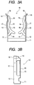
- Figs. 3A and 3B are a front explanatory drawing and a side explanatory drawing of the pipe fitting.
- a pipe fitting 10 is integrally formed by pressing a substantially square metal plate 1, in which opening portions 2 and a cutout portion 3 are formed by punching.
- the metal plate 1 of Fig. 2 is folded at the dotted line portions to form right angles and pressed to form uneven surfaces in side pieces 12, the metal plate 1 becomes the pipe fitting 10 having a three-dimensional shape such as the one shown in Fig. 1.
- the side pieces 12 are folded with respect to a connecting piece 11, which comprises a rectangular piece positioned at a front lower portion of the pipe fitting 10, so that the side pieces 12 are disposed facing each other at both sides of the connecting piece 11.
- the connecting piece 11 and the side pieces 12 are connected at end portions of the side pieces 12.
- a fitting hole portion 13 (opening portions 2 in Fig. 2) is formed in each side piece 12, and arced support portions 15, which are disposed in a plane orthogonal to the side pieces 12 via foot pieces 14, are formed. That is, side wall 16 portions of the arced support portions 15 are disposed so as to face each other by folding the foot pieces 14 so that the foot pieces 14 are orthogonal to each side piece 12. Therefore, because each arced support portion 15 and the connecting piece 11 are folded and formed so that they are all orthogonal to the side pieces 12, they are disposed on the same plane.
- the arced support portions 15 sandwich the small-diameter pipe from both sides with the side walls 16.
- Flange portions are insertable into the fitting hole portions 13 of the side pieces 12 in a state in which the large-diameter pipe and the small-diameter pipe are brought into contact and connected.
- the curved portions 17 contact parts of the periphery of the large-diameter pipe and can support the large-diameter pipe.
- Folded portions 18, which are folded so as to spread outward, are formed at end portions of the side pieces 12 opposite from the end portions of the side pieces 12 connected to the connecting piece 11. Moreover, guide grooves 19, which are protruded outwward, are formed in the folded portions 18 and at positions to the sides of the fitting holes portions 13 in the side pieces 12 that are continuous with the folded portions 18.
- a flange portion 81 of the large-diameter pipe 80 and a flange portion 91 of the small-diameter pipe 90 are brought into contact, and the portions at which the flange portions contact are inserted through the pipe fitting 10 from the folded portions 18 side.
- the flange portions can easily be inserted through the pipe fitting 10 and the portions at which the flange portions 81 and 91 contact are guided, whereby the flange portions 81 and 91 can be vertically inserted through the pipe fitting 10.
- both side pieces 12 widen, whereby the portions at which the flange portions contact are fitted and disposed in the fitting hole portions 13, the side walls 16 support the small-diameter pipe 90, and the curved portions 17 of the side pieces 17 support the large-diameter pipe 80, whereby the contact state is maintained.
- Fig. 5 shows another embodiment of the invention, and the same reference numerals will be given to portions that have the same constitution as those in Fig. 1.
- the pipe fitting 10 of Fig. 5 is one in which the shape of support portions 25 supporting the small-diameter pipe 90 are different in comparison to those of the pipe fitting 10 of Fig. 1. That is, whereas the arced support portions 15 along the shape of the small-diameter pipe 90 served as the support portions in the pipe fitting 10 of Fig. 1, the support portions 25, which sandwich the small-diameter pipe between straight portions 25a positioned to face each other, are formed. Other configurations are the same as those of the pipe fitting 10 of Fig. 1.
- Fig. 6 shows another embodiment of the invention, and the same reference numerals will be given to portions that have the same constitution as those in Fig. 1.
- the pipe fitting 10 of Fig. 6 is one in which the shape of support portions 35 supporting the small-diameter pipe 90 are different in comparison to those of the pipe fitting 10 of Fig. 1. That is, a vertical flange portion 35a, which is an arced curved surface vertically disposed across each entire arced support portion 15, is formed at the support side of each arced support portion 15 of the pipe fitting 10 shown in Fig. 1 so that the vertical flange portions 35a face each other and support the small-diameter pipe 90.
- the small-diameter pipe 90 can be more reliably supported due to the support portions 35 that include the vertical flange portions 35a.
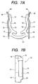
- Figs. 7A and 7B show another embodiment of the invention, and the same reference numerals will be given to portions that have the same constitution as those in Fig. 1.
- the pipe fitting 10 of Figs. 7A and 7B is one in which the shape and formation position of the connecting piece are different in comparison to those of the pipe fitting 10 of Fig. 3. That is, although the connecting piece 11 is disposed at the endmost portion in the same plane as the arced support portions 15 of the side pieces 15 in the pipe fitting 10 of Fig. 3, in this example, the connecting piece is configured by an arced piece 21 that connects positions slightly distanced from the end portions of the side pieces 12. The arced piece 21 is also connected to the foot portions 14.
- Figs. 8A and 8B show another embodiment of the invention, and the same reference numerals will be given to portions that have the same constitution as those in Fig. 1.
- the pipe fitting 10 of Figs. 8A and 8B is one in which the position at which the connecting piece is formed with respect to the side pieces 12 is different in comparison to that of the pipe fitting 10 of Fig. 3. That is, in this example, a connecting piece 31 is configured to connect short ends (lower end edges) of the side pieces 12 and is disposed in a plane orthogonal to the arced support portions 15. That is, the connecting piece 31 connects the end portions of the side pieces 12 at a plane orthogonal to the arced support portions 15.
- the spring constant is made smaller in comparison to the pipe fitting of Fig. 3 (i.e., the pipe fitting can be structured so that the side pieces 12 are easy to spread).
- the pipe fitting 10 of each of the aforementioned embodiments has a spring action due to the side pieces 12 and the connecting pieces 11 and 31 (arced pieces 21), the large-diameter pipe 80 is supported by the pair of side pieces 12 that are disposed so as to face each other, and the large-diameter pipe 90 is supported by the side walls 16 (straight portions 25a and vertical flange portions 35a) of the arced support portions 15 (support portions 25 and support portions 35) that are disposed so that they are folded orthogonally to the side pieces 12.
- the connecting pieces 11 and 31 (arced pieces 21) can be disposed in a plane orthogonal to the side pieces 12.
- twisting does not arise in the overall shape of the pipe fitting 10, and the pipe fitting 10 can reliably support the pipes.
- the pipe fitting 10 can be integrally and easily formed by pressing the metal plate 1 to dispose the opening portions 2 and the cutout portions 3, it becomes possible to inexpensively manufacture the pipe fitting 10.
- the pipe fitting when the pipe fitting is fitted to a portion at which a large-diameter pipe and a small-diameter are connected, the pipe fitting has a spring action due to the side pieces and the connecting piece, the large-diameter pipe is supported by the pair of side pieces that are disposed so as to face each other, and the large-diameter pipe is supported by the side walls of the arced support portions that are disposed so that they are folded orthogonally to the side pieces.
- twisting does not arise in the integrally formed pipe fitting, and the pipe fitting can reliably support the pipes.
Landscapes
- Engineering & Computer Science (AREA)
- General Engineering & Computer Science (AREA)
- Mechanical Engineering (AREA)
- Mutual Connection Of Rods And Tubes (AREA)
- Flanged Joints, Insulating Joints, And Other Joints (AREA)
- Quick-Acting Or Multi-Walled Pipe Joints (AREA)
- Branch Pipes, Bends, And The Like (AREA)
- Supports For Pipes And Cables (AREA)
Applications Claiming Priority (4)
| Application Number | Priority Date | Filing Date | Title |
|---|---|---|---|
| JP2002156381 | 2002-05-29 | ||
| JP2002156381 | 2002-05-29 | ||
| JP2002300761 | 2002-10-15 | ||
| JP2002300761A JP3914488B2 (ja) | 2002-05-29 | 2002-10-15 | 配管接続金具 |
Publications (3)
| Publication Number | Publication Date |
|---|---|
| EP1367310A2 true EP1367310A2 (fr) | 2003-12-03 |
| EP1367310A3 EP1367310A3 (fr) | 2003-12-10 |
| EP1367310B1 EP1367310B1 (fr) | 2007-01-31 |
Family
ID=29422466
Family Applications (1)
| Application Number | Title | Priority Date | Filing Date |
|---|---|---|---|
| EP03012067A Expired - Lifetime EP1367310B1 (fr) | 2002-05-29 | 2003-05-28 | Raccord de tuyauterie |
Country Status (4)
| Country | Link |
|---|---|
| US (1) | US20040017084A1 (fr) |
| EP (1) | EP1367310B1 (fr) |
| JP (1) | JP3914488B2 (fr) |
| DE (1) | DE60311538T2 (fr) |
Families Citing this family (3)
| Publication number | Priority date | Publication date | Assignee | Title |
|---|---|---|---|---|
| JP4869962B2 (ja) * | 2007-01-29 | 2012-02-08 | 株式会社キッツ | メータユニット |
| US8087703B2 (en) * | 2007-04-20 | 2012-01-03 | Piolax Inc. | Component connecting structure |
| US11377976B2 (en) * | 2018-12-19 | 2022-07-05 | Unison Industries, Llc | Surface cooler and method of forming |
Citations (1)
| Publication number | Priority date | Publication date | Assignee | Title |
|---|---|---|---|---|
| JP2001099376A (ja) | 1999-09-30 | 2001-04-10 | Noritz Corp | 差込み式管継手 |
Family Cites Families (17)
| Publication number | Priority date | Publication date | Assignee | Title |
|---|---|---|---|---|
| DE3146888A1 (de) * | 1981-11-26 | 1983-06-01 | Bayerische Motoren Werke AG, 8000 München | Halteklammer |
| DE3146889C2 (de) * | 1981-11-26 | 1986-04-30 | Bayerische Motoren Werke AG, 8000 München | Kraftstoffeinspritzanordnung für Brennkraftmaschinen |
| DE8613607U1 (de) * | 1986-05-20 | 1986-09-11 | Springfix-Befestigungstechnik GmbH, 73084 Salach | Federklemme zum Verbinden rohrförmiger Bauteile |
| JPS63125171U (fr) * | 1987-02-09 | 1988-08-16 | ||
| GB8926363D0 (en) * | 1989-11-22 | 1990-01-10 | Lucas Ind Plc | Fuel injection system |
| DE4017875C2 (de) * | 1990-06-02 | 1999-02-04 | Bosch Gmbh Robert | Brennstoffeinspritzeinrichtung für Brennkraftmaschinen |
| US5074269A (en) * | 1991-04-29 | 1991-12-24 | Chrysler Corporation | Anti-rotation fuel injector clip |
| DE4217646C1 (en) * | 1992-05-28 | 1993-09-16 | Mercedes-Benz Aktiengesellschaft, 70327 Stuttgart, De | Push in connector for two pipe sections - has coaxially interfitting connectors with spring clip locked even in release position on one part by locking element with detent allowing pre-fitting |
| JP3765336B2 (ja) * | 1996-10-15 | 2006-04-12 | 株式会社デンソー | 燃料供給装置およびその製造方法 |
| US5803052A (en) * | 1997-06-27 | 1998-09-08 | Siemens Automotive Corporation | Spring clip for retaining a fuel injector in a fuel rail cup |
| US6053149A (en) * | 1998-05-28 | 2000-04-25 | Siemens Automotive Corporation | Fuel injector clip retention arrangement |
| US5970953A (en) * | 1999-01-12 | 1999-10-26 | Siemens Automotive Corporation | High pressure injector clip |
| JP3828701B2 (ja) * | 1999-12-29 | 2006-10-04 | 株式会社ケーヒン | 燃料分配管への燃料噴射弁の取付け構造 |
| US6481420B2 (en) * | 2001-01-30 | 2002-11-19 | Visteon Global Technologies, Inc. | Method and apparatus for maintaining the alignment of a fuel injector |
| DE10213585A1 (de) * | 2001-03-27 | 2002-10-02 | Denso Corp | Kraftstoffzufuhrvorrichtung mit einem Herausrutschverhinderungselement |
| US6705292B2 (en) * | 2002-04-02 | 2004-03-16 | Siemens Vdo Automotive Corporation | Apparatus and method of connecting a fuel injector and a fuel rail |
| US6668803B1 (en) * | 2002-12-03 | 2003-12-30 | Ford Global Technologies, Llc | Fuel injector retention arrangement |
-
2002
- 2002-10-15 JP JP2002300761A patent/JP3914488B2/ja not_active Expired - Fee Related
-
2003
- 2003-05-28 EP EP03012067A patent/EP1367310B1/fr not_active Expired - Lifetime
- 2003-05-28 US US10/445,893 patent/US20040017084A1/en not_active Abandoned
- 2003-05-28 DE DE60311538T patent/DE60311538T2/de not_active Expired - Fee Related
Patent Citations (1)
| Publication number | Priority date | Publication date | Assignee | Title |
|---|---|---|---|---|
| JP2001099376A (ja) | 1999-09-30 | 2001-04-10 | Noritz Corp | 差込み式管継手 |
Also Published As
| Publication number | Publication date |
|---|---|
| US20040017084A1 (en) | 2004-01-29 |
| EP1367310B1 (fr) | 2007-01-31 |
| DE60311538T2 (de) | 2007-05-16 |
| DE60311538D1 (de) | 2007-03-22 |
| JP3914488B2 (ja) | 2007-05-16 |
| EP1367310A3 (fr) | 2003-12-10 |
| JP2004053000A (ja) | 2004-02-19 |
Similar Documents
| Publication | Publication Date | Title |
|---|---|---|
| JPH10233251A (ja) | 一体構成の接触ばね | |
| EP3041090A1 (fr) | Borne à ajustement serré, connecteur comprenant cette dernière, ensemble homogène comprenant une borne à ajustement serré, et corps enroulé avec un ensemble homogène comprenant une borne à ajustement serré | |
| US20190111857A1 (en) | U-base fastener with folded barb and multiple spring arms | |
| JPH0737635A (ja) | 電気接続端子 | |
| JP2005056792A (ja) | 雌端子金具 | |
| US7166002B2 (en) | Connection terminal | |
| JP7503142B2 (ja) | トリプルロックメインティースプライス | |
| JP2000077126A (ja) | リセプタクル型電気コンタクト | |
| US6790105B2 (en) | Male terminal fitting | |
| EP1225367B1 (fr) | Masse d'équilibrage pour véhicule à deux roues | |
| US5716246A (en) | Contact device for electric plug connections | |
| US20040017084A1 (en) | Pipe fitting | |
| CN111576873B (zh) | 方通扣以及紧固方法 | |
| JPH0742004U (ja) | 雌型端子 | |
| KR100602740B1 (ko) | 서랍 안내장치 및 그 서랍안내장치의 조립 및 제조방법 | |
| EP3581813A1 (fr) | Fixation à base en u à ardillon plié et plusieurs bras à ressort | |
| TWI616037B (zh) | 連接器及其製造方法 | |
| US7261604B2 (en) | Electrical terminal element | |
| CN212376279U (zh) | 方通扣 | |
| JP3144457U (ja) | 配管接続金具 | |
| EP1096612A1 (fr) | Fiche de contact pour connecteur électrique | |
| JP2010078016A (ja) | ホース保持構造およびホース固定用のクリップ | |
| JP2001201640A (ja) | 配線固定具 | |
| JP3062621B2 (ja) | 大電流用リード線接続装置 | |
| JP2000133356A (ja) | ソケットコンタクト |
Legal Events
| Date | Code | Title | Description |
|---|---|---|---|
| PUAI | Public reference made under article 153(3) epc to a published international application that has entered the european phase |
Free format text: ORIGINAL CODE: 0009012 |
|
| PUAL | Search report despatched |
Free format text: ORIGINAL CODE: 0009013 |
|
| AK | Designated contracting states |
Kind code of ref document: A2 Designated state(s): AT BE BG CH CY CZ DE DK EE ES FI FR GB GR HU IE IT LI LU MC NL PT RO SE SI SK TR |
|
| AX | Request for extension of the european patent |
Extension state: AL LT LV MK |
|
| AK | Designated contracting states |
Kind code of ref document: A3 Designated state(s): AT BE BG CH CY CZ DE DK EE ES FI FR GB GR HU IE IT LI LU MC NL PT RO SE SI SK TR |
|
| AX | Request for extension of the european patent |
Extension state: AL LT LV MK |
|
| 17P | Request for examination filed |
Effective date: 20040317 |
|
| 17Q | First examination report despatched |
Effective date: 20040521 |
|
| AKX | Designation fees paid |
Designated state(s): DE FR GB |
|
| GRAP | Despatch of communication of intention to grant a patent |
Free format text: ORIGINAL CODE: EPIDOSNIGR1 |
|
| GRAS | Grant fee paid |
Free format text: ORIGINAL CODE: EPIDOSNIGR3 |
|
| GRAA | (expected) grant |
Free format text: ORIGINAL CODE: 0009210 |
|
| AK | Designated contracting states |
Kind code of ref document: B1 Designated state(s): DE FR GB |
|
| REG | Reference to a national code |
Ref country code: GB Ref legal event code: FG4D |
|
| REF | Corresponds to: |
Ref document number: 60311538 Country of ref document: DE Date of ref document: 20070322 Kind code of ref document: P |
|
| ET | Fr: translation filed | ||
| PLBE | No opposition filed within time limit |
Free format text: ORIGINAL CODE: 0009261 |
|
| STAA | Information on the status of an ep patent application or granted ep patent |
Free format text: STATUS: NO OPPOSITION FILED WITHIN TIME LIMIT |
|
| 26N | No opposition filed |
Effective date: 20071101 |
|
| PGFP | Annual fee paid to national office [announced via postgrant information from national office to epo] |
Ref country code: DE Payment date: 20080605 Year of fee payment: 6 |
|
| PGFP | Annual fee paid to national office [announced via postgrant information from national office to epo] |
Ref country code: GB Payment date: 20080528 Year of fee payment: 6 |
|
| GBPC | Gb: european patent ceased through non-payment of renewal fee |
Effective date: 20090528 |
|
| REG | Reference to a national code |
Ref country code: FR Ref legal event code: ST Effective date: 20100129 |
|
| PG25 | Lapsed in a contracting state [announced via postgrant information from national office to epo] |
Ref country code: FR Free format text: LAPSE BECAUSE OF NON-PAYMENT OF DUE FEES Effective date: 20090602 |
|
| PGFP | Annual fee paid to national office [announced via postgrant information from national office to epo] |
Ref country code: FR Payment date: 20080514 Year of fee payment: 6 |
|
| PG25 | Lapsed in a contracting state [announced via postgrant information from national office to epo] |
Ref country code: GB Free format text: LAPSE BECAUSE OF NON-PAYMENT OF DUE FEES Effective date: 20090528 |
|
| PG25 | Lapsed in a contracting state [announced via postgrant information from national office to epo] |
Ref country code: DE Free format text: LAPSE BECAUSE OF NON-PAYMENT OF DUE FEES Effective date: 20091201 |