EP1367312A1 - Drehknopf zum Feststellen eines Geräteträgers - Google Patents
Drehknopf zum Feststellen eines Geräteträgers Download PDFInfo
- Publication number
- EP1367312A1 EP1367312A1 EP02405440A EP02405440A EP1367312A1 EP 1367312 A1 EP1367312 A1 EP 1367312A1 EP 02405440 A EP02405440 A EP 02405440A EP 02405440 A EP02405440 A EP 02405440A EP 1367312 A1 EP1367312 A1 EP 1367312A1
- Authority
- EP
- European Patent Office
- Prior art keywords
- handle
- rotary knob
- shell
- clamping disc
- sleeve
- Prior art date
- Legal status (The legal status is an assumption and is not a legal conclusion. Google has not performed a legal analysis and makes no representation as to the accuracy of the status listed.)
- Granted
Links
Images


Classifications
-
- G—PHYSICS
- G05—CONTROLLING; REGULATING
- G05G—CONTROL DEVICES OR SYSTEMS INSOFAR AS CHARACTERISED BY MECHANICAL FEATURES ONLY
- G05G1/00—Controlling members, e.g. knobs or handles; Assemblies or arrangements thereof; Indicating position of controlling members
- G05G1/08—Controlling members for hand actuation by rotary movement, e.g. hand wheels
- G05G1/10—Details, e.g. of discs, knobs, wheels or handles
-
- F—MECHANICAL ENGINEERING; LIGHTING; HEATING; WEAPONS; BLASTING
- F16—ENGINEERING ELEMENTS AND UNITS; GENERAL MEASURES FOR PRODUCING AND MAINTAINING EFFECTIVE FUNCTIONING OF MACHINES OR INSTALLATIONS; THERMAL INSULATION IN GENERAL
- F16M—FRAMES, CASINGS OR BEDS OF ENGINES, MACHINES OR APPARATUS, NOT SPECIFIC TO ENGINES, MACHINES OR APPARATUS PROVIDED FOR ELSEWHERE; STANDS; SUPPORTS
- F16M11/00—Stands or trestles as supports for apparatus or articles placed thereon ; Stands for scientific apparatus such as gravitational force meters
- F16M11/02—Heads
- F16M11/04—Means for attachment of apparatus; Means allowing adjustment of the apparatus relatively to the stand
- F16M11/06—Means for attachment of apparatus; Means allowing adjustment of the apparatus relatively to the stand allowing pivoting
-
- Y—GENERAL TAGGING OF NEW TECHNOLOGICAL DEVELOPMENTS; GENERAL TAGGING OF CROSS-SECTIONAL TECHNOLOGIES SPANNING OVER SEVERAL SECTIONS OF THE IPC; TECHNICAL SUBJECTS COVERED BY FORMER USPC CROSS-REFERENCE ART COLLECTIONS [XRACs] AND DIGESTS
- Y10—TECHNICAL SUBJECTS COVERED BY FORMER USPC
- Y10T—TECHNICAL SUBJECTS COVERED BY FORMER US CLASSIFICATION
- Y10T74/00—Machine element or mechanism
- Y10T74/20—Control lever and linkage systems
- Y10T74/20576—Elements
- Y10T74/20732—Handles
- Y10T74/20834—Hand wheels
- Y10T74/2084—Knob or dial
Definitions
- the invention relates to a rotary knob for locking of an equipment rack.
- the knob 1 shows a known knob for locking a device carrier in a housing by means of a Clamping device with a spindle.
- the turret is on Housing and mounted on the spindle.
- the knob comprises a grip shell 1 with an internal thread, a Coupling part 2 for connecting the handle shell 1 with the Spindle, a sleeve 3, which can be connected to the housing is, a cover plate 4 with the sleeve 3 on the housing is attached, a screw 5 for adjusting the Locking force, which is arranged in the handle 1 and a clamping disc 6, the one with the internal thread of the Handle shell is in engagement with the external thread and which is guided on the sleeve 3, such that by Turn the grip 1 the clamping disc 6 a Relative movement with respect to the handle 1 executes.
- the handle 1 rotated clockwise. This will make the Clamping device operated by the spindle and the Clamping disc 6 axially displaced until the equipment carrier is established.
- the position of the Clamping disc set which of the required Locking force for the equipment carrier corresponds. Come Devices for use for which different Locking forces are required the position reset each time.
- the device carrier will hold the clamping disc until it comes into contact the screw 5 shifted and thereby a rotation of the Handle 1 prevented. This is the equipment carrier detected.
- the invention has for its object a rotary knob improve in this regard, so a trouble-free locking and loosening of the device carrier is guaranteed.
- the clamping effect can be turned by turning the handle 1 in the opposite direction.
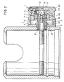
- the knob contains one Handle shell 1, a coupling part 2 for connecting the Handle shell 1 with the spindle, a sleeve 3, one Cover plate 4 a screw 5 for adjusting the Locking force, a clamping disc 6, a ring scale 7 and an organ 8 to secure the screw against losing.
- the handle 1 is made of plastic or metal.
- the grip shell 1 has a guide part 11 with a Hexagon hole 12, which is fastened in the grip 1 and a threaded hole in the base 13 of the shell.
- the Coupling part 2 has a flange 21 at one end, a hex section 22 at the other end and one Bore 23 with a first threaded portion 24 and with a second threaded section 25.
- the Coupling part 2 is with the first threaded section 24 screwed onto the spindle
- the sleeve 3 has a first Threaded portion 31, a second threaded portion 32 and a hexagonal section 33 and is with the first threaded portion 31 attached to the housing.
- the Sleeve 3 encloses the coupling part 2 and lies on Flange 21 on.
- the cover plate 4 is in contact with the housing attached by means of the sleeve 3.
- the screw 5 is in that Threaded hole screwed into the base of the shell.
- the clamping disc 6 is designed as a hexagon nut and is on the second threaded section 32 screwed on as well Hexagon socket of the guide part 11 arranged.
- the The ring scale 7 is rotatably arranged on the handle 1.
- the grip shell 1 and a securing element 8 are by means of a screw 9 held on the coupling part 2.
- the handle 1 and the clamping disc 6 rotated clockwise together and thereby the clamping disc 6 linear with respect to Handle shell moved until the device carrier is established. Then the adjusting screw 5 to screwed against the clamping disc 6. Thereby the required locking force is set and saved at the same time, so when re- Always check the after each loosening of the device carrier same position of the clamping disc 5 and the same Locking force is achieved (Fig.3).
- the device carrier is the ring scale 7 and the cover plate 4 with a marking on the circumference Mistake.
- the rotary knob on a tripod head can be provided, which is disclosed in EP A 0 349 948 is.
Landscapes
- Engineering & Computer Science (AREA)
- General Engineering & Computer Science (AREA)
- Mechanical Engineering (AREA)
- Physics & Mathematics (AREA)
- General Physics & Mathematics (AREA)
- Automation & Control Theory (AREA)
- Mechanical Control Devices (AREA)
- Clamps And Clips (AREA)
- Lock And Its Accessories (AREA)
- Preventing Unauthorised Actuation Of Valves (AREA)
- Gripping Jigs, Holding Jigs, And Positioning Jigs (AREA)
- Fixing For Electrophotography (AREA)
Abstract
Description
- Fig.1
- Einen Schnitt durch eine bekannte Ausführung eines Drehknopfes;
- Fig.2
- einen Schnitt durch eine erfindungsgemässe Ausführung bei gelösten Geräteträger und
- Fig.3
- den Schnitt gemäss Fig.2 bei festgestellten Geräteträger.
Claims (7)
- Drehknopf zum Feststellen eines Geräteträgers in einem Gehäuse mittels einer Vorrichtung mit einer Spindel, welcher Drehknopf eine Griffschale (1), einen Kupplungsteil (2) zum Verbinden der Griffschale mit der Spindel, eine Hülse (3), die mit dem Gehäuse verbindbar ist, eine Deckscheibe (4), die mit der Hülse (3) am Gehäuse befestigt ist, eine Schraube (5) zum Einstellen der Feststellkraft, die im Schalengrund (13) angeordnet ist und eine Klemmscheibe (6), die mit der Griffschale (1) und der Hülse (3) zusammenwirkt, so dass durch Drehen der Griffschale (1) die Klemmscheibe (6) eine Relativbewegung ausführt und zum Begrenzen der Drehung der Griffschale (1) mit der Schraube (5) in Anlage bringbar ist, dadurch gekennzeichnet, dass die Klemmscheibe (6) in der Griffschale (1) geführt und auf der Hülse (3) drehbar angeordnet ist, so dass durch Drehen der Griffschale (1) die Klemmscheibe (6) eine synchrone Drehbewegung mit der Griffschale (1) und eine lineare Bewegung bezüglich der Griffschale (1) ausführt.
- Drehknopf nach Anspruch 1, dadurch gekennzeichnet, dass der Kupplungsteil (2) einen Flansch (21) ausweist.
- Drehknopf nach Anspruch 1, dadurch gekennzeichnet, dass, die Deckscheibe (4) am Umfang mit einer Markierung versehen ist.
- Drehknopf nach Anspruch 2, gekennzeichnet durch eine Ringskala (7), die drehbar am Umfang der Griffschale 1 angeordnet ist.
- Drehknopf nach Anspruch 3, dadurch gekennzeichnet, dass die Ringskala (7) mit mindestens einer Markierung am Umfang aufweist.
- Drehknopf nach Anspruch 3, gekennzeichnet durch ein Sicherungsorgan (8) für die Einstellschraube (5).
- Drehknopf nach Anspruch 1, dadurch gekennzeichnet, dass die Griffschale (1) aus Kunststoff oder Metall besteht.
Priority Applications (6)
| Application Number | Priority Date | Filing Date | Title |
|---|---|---|---|
| DE50212472T DE50212472D1 (de) | 2002-05-31 | 2002-05-31 | Drehknopf zum Feststellen eines Geräteträgers |
| AT02405440T ATE400770T1 (de) | 2002-05-31 | 2002-05-31 | Drehknopf zum feststellen eines geräteträgers |
| EP02405440A EP1367312B1 (de) | 2002-05-31 | 2002-05-31 | Drehknopf zum Feststellen eines Geräteträgers |
| US10/452,169 US7013752B2 (en) | 2002-05-31 | 2003-05-30 | Rotatable knob for the fixation of an apparatus support |
| CN03136368.7A CN1268189C (zh) | 2002-05-31 | 2003-06-02 | 固定仪器底板的旋钮 |
| HK04101889.8A HK1059534B (en) | 2002-05-31 | 2004-03-15 | Rotatable knob for the fixation of an apparatus support |
Applications Claiming Priority (1)
| Application Number | Priority Date | Filing Date | Title |
|---|---|---|---|
| EP02405440A EP1367312B1 (de) | 2002-05-31 | 2002-05-31 | Drehknopf zum Feststellen eines Geräteträgers |
Publications (2)
| Publication Number | Publication Date |
|---|---|
| EP1367312A1 true EP1367312A1 (de) | 2003-12-03 |
| EP1367312B1 EP1367312B1 (de) | 2008-07-09 |
Family
ID=29414855
Family Applications (1)
| Application Number | Title | Priority Date | Filing Date |
|---|---|---|---|
| EP02405440A Expired - Lifetime EP1367312B1 (de) | 2002-05-31 | 2002-05-31 | Drehknopf zum Feststellen eines Geräteträgers |
Country Status (5)
| Country | Link |
|---|---|
| US (1) | US7013752B2 (de) |
| EP (1) | EP1367312B1 (de) |
| CN (1) | CN1268189C (de) |
| AT (1) | ATE400770T1 (de) |
| DE (1) | DE50212472D1 (de) |
Families Citing this family (4)
| Publication number | Priority date | Publication date | Assignee | Title |
|---|---|---|---|---|
| FI115997B (fi) * | 2004-01-30 | 2005-08-31 | Abb Oy | Järjestely kytkimen ohjainakselin kiinnittämiseksi kytkimen putkiakseliin |
| CN101945554B (zh) * | 2009-07-03 | 2012-11-07 | 纬创资通股份有限公司 | 用来遮蔽壳体的开口的盖板机构 |
| CN101839388B (zh) * | 2010-05-18 | 2011-09-07 | 河海大学 | 一种适于工字形钢架结构的仪器安装平台 |
| CN202120021U (zh) * | 2011-03-14 | 2012-01-18 | 中山市思锐摄影器材工业有限公司 | 摄影云台锁紧装置 |
Citations (5)
| Publication number | Priority date | Publication date | Assignee | Title |
|---|---|---|---|---|
| US2719690A (en) * | 1952-10-01 | 1955-10-04 | Frank C Zucker | Universal tripod head and tilt brake therefor |
| US2998733A (en) * | 1959-06-02 | 1961-09-05 | Kenneth W Thompson | Control device |
| US4154125A (en) * | 1977-07-05 | 1979-05-15 | Beckman Instruments, Inc. | Knob locking and drag device |
| EP0349948A1 (de) | 1988-07-06 | 1990-01-10 | Philippe Vogt | Stativkopf |
| US6352228B1 (en) * | 1998-08-29 | 2002-03-05 | FLM GmbH Foto-, Licht-und Messtechnisches Zubehör | Tripod head |
Family Cites Families (5)
| Publication number | Priority date | Publication date | Assignee | Title |
|---|---|---|---|---|
| US2522779A (en) * | 1945-09-27 | 1950-09-19 | Culkosky Martin | Lathe control |
| US3570531A (en) * | 1969-08-22 | 1971-03-16 | John B Mcgay | Tube pincher for intravenous administration |
| US3759424A (en) * | 1970-12-28 | 1973-09-18 | E Maddock | Lubricant dispensing means and system |
| US4012966A (en) * | 1975-11-17 | 1977-03-22 | Jan Hardware Manufacturing, Inc. | Knob and control shaft assembly with brake |
| FR2745398B1 (fr) * | 1996-02-28 | 1998-05-07 | Sundstrand Corp | Dispositif de verrouillage de la position angulaire d'un bouton de manoeuvre |
-
2002
- 2002-05-31 DE DE50212472T patent/DE50212472D1/de not_active Expired - Lifetime
- 2002-05-31 AT AT02405440T patent/ATE400770T1/de not_active IP Right Cessation
- 2002-05-31 EP EP02405440A patent/EP1367312B1/de not_active Expired - Lifetime
-
2003
- 2003-05-30 US US10/452,169 patent/US7013752B2/en not_active Expired - Lifetime
- 2003-06-02 CN CN03136368.7A patent/CN1268189C/zh not_active Expired - Fee Related
Patent Citations (5)
| Publication number | Priority date | Publication date | Assignee | Title |
|---|---|---|---|---|
| US2719690A (en) * | 1952-10-01 | 1955-10-04 | Frank C Zucker | Universal tripod head and tilt brake therefor |
| US2998733A (en) * | 1959-06-02 | 1961-09-05 | Kenneth W Thompson | Control device |
| US4154125A (en) * | 1977-07-05 | 1979-05-15 | Beckman Instruments, Inc. | Knob locking and drag device |
| EP0349948A1 (de) | 1988-07-06 | 1990-01-10 | Philippe Vogt | Stativkopf |
| US6352228B1 (en) * | 1998-08-29 | 2002-03-05 | FLM GmbH Foto-, Licht-und Messtechnisches Zubehör | Tripod head |
Also Published As
| Publication number | Publication date |
|---|---|
| ATE400770T1 (de) | 2008-07-15 |
| CN1462174A (zh) | 2003-12-17 |
| US7013752B2 (en) | 2006-03-21 |
| HK1059534A1 (en) | 2004-07-02 |
| DE50212472D1 (de) | 2008-08-21 |
| US20030221510A1 (en) | 2003-12-04 |
| EP1367312B1 (de) | 2008-07-09 |
| CN1268189C (zh) | 2006-08-02 |
Similar Documents
| Publication | Publication Date | Title |
|---|---|---|
| DE3206789C2 (de) | Gelenkiger Tragarm | |
| DE69735490T2 (de) | Klammer als halterung für einen wundsperrer | |
| EP1344494A2 (de) | Zielgerät für Verriegelungsnägel | |
| WO1994019787A1 (de) | Für demonstrations- und/oder schulungszwecke verwendbares funktionselement | |
| DE10316577A1 (de) | Linearführungsschienen-Haltevorrichtung | |
| EP0713018A1 (de) | Verbindungsanordnung | |
| DE3923131A1 (de) | Befestigungselement, insbesondere fuer eine kugel-gewindespindel | |
| EP2097199B1 (de) | Systempendelvorrichtung und verfahren | |
| DE4115253C2 (de) | ||
| EP1367312B1 (de) | Drehknopf zum Feststellen eines Geräteträgers | |
| DE19734866C1 (de) | Vorrichtung zum Verbinden zweier Bauteile | |
| DE3232496C2 (de) | Vorrichtung zur verschwenk- und feststellbaren Lagerung eines Maschinenschraubstockes auf einem Werkzeug-Maschinentisch | |
| DE2633968C3 (de) | Einstellvorrichtung für den optischen Block eines Scheinwerfers | |
| DE3704764A1 (de) | Einrichtung zum einstellen einer drehmomentbegrenzung an einem schraubendreher | |
| DE29901803U1 (de) | Klemmvorrichtung zum Klemmen eines Gegenstandes | |
| DE3829030C2 (de) | Verstellbare Verriegelungsvorrichtung zum Befestigen eines Bauteils an einem anderen Bauteil | |
| DE8903660U1 (de) | Stützvorrichtung für Werkstücke | |
| CH625572A5 (de) | ||
| EP1344605B1 (de) | Spannwerkzeug | |
| DE102017114906B3 (de) | Sensorgehäuse zur Fixierung in verschiedenen C-Nutvarianten metallischer Befestigungskörper durch unterschiedliche Klemmflächenpaare | |
| DE3407624C2 (de) | Haltevorrichtung für ein Werkzeug, insbesondere Schutzgasschweißbrenner, in einem programmgesteuerten Handhabungsautomaten | |
| DE1299485B (de) | Bohrkopf | |
| EP1245200B1 (de) | Bissgabelträger mit Zentralklemmung | |
| DE2913938C3 (de) | Befestigungseinrichtung für ein Gehäuse-Verschlußteil, insbesondere für Schaltkästen mit elektrischen Schalteinrichtungen | |
| DE3624395A1 (de) | Gewindeeinsatz |
Legal Events
| Date | Code | Title | Description |
|---|---|---|---|
| PUAI | Public reference made under article 153(3) epc to a published international application that has entered the european phase |
Free format text: ORIGINAL CODE: 0009012 |
|
| AK | Designated contracting states |
Kind code of ref document: A1 Designated state(s): AT BE CH CY DE DK ES FI FR GB GR IE IT LI LU MC NL PT SE TR |
|
| AX | Request for extension of the european patent |
Extension state: AL LT LV MK RO SI |
|
| 17P | Request for examination filed |
Effective date: 20040426 |
|
| AKX | Designation fees paid |
Designated state(s): AT BE CH CY DE DK ES FI FR GB GR IE IT LI LU MC NL PT SE TR |
|
| RAP1 | Party data changed (applicant data changed or rights of an application transferred) |
Owner name: VOGT, PHILIPPE |
|
| RIN1 | Information on inventor provided before grant (corrected) |
Inventor name: VOGT, PHILIPPE |
|
| GRAP | Despatch of communication of intention to grant a patent |
Free format text: ORIGINAL CODE: EPIDOSNIGR1 |
|
| GRAS | Grant fee paid |
Free format text: ORIGINAL CODE: EPIDOSNIGR3 |
|
| GRAA | (expected) grant |
Free format text: ORIGINAL CODE: 0009210 |
|
| AK | Designated contracting states |
Kind code of ref document: B1 Designated state(s): AT BE CH CY DE DK ES FI FR GB GR IE IT LI LU MC NL PT SE TR |
|
| REG | Reference to a national code |
Ref country code: GB Ref legal event code: FG4D Free format text: NOT ENGLISH |
|
| REG | Reference to a national code |
Ref country code: CH Ref legal event code: EP |
|
| REF | Corresponds to: |
Ref document number: 50212472 Country of ref document: DE Date of ref document: 20080821 Kind code of ref document: P |
|
| REG | Reference to a national code |
Ref country code: IE Ref legal event code: FG4D Free format text: LANGUAGE OF EP DOCUMENT: GERMAN |
|
| PG25 | Lapsed in a contracting state [announced via postgrant information from national office to epo] |
Ref country code: ES Free format text: LAPSE BECAUSE OF FAILURE TO SUBMIT A TRANSLATION OF THE DESCRIPTION OR TO PAY THE FEE WITHIN THE PRESCRIBED TIME-LIMIT Effective date: 20081020 Ref country code: PT Free format text: LAPSE BECAUSE OF FAILURE TO SUBMIT A TRANSLATION OF THE DESCRIPTION OR TO PAY THE FEE WITHIN THE PRESCRIBED TIME-LIMIT Effective date: 20081209 |
|
| PG25 | Lapsed in a contracting state [announced via postgrant information from national office to epo] |
Ref country code: FI Free format text: LAPSE BECAUSE OF FAILURE TO SUBMIT A TRANSLATION OF THE DESCRIPTION OR TO PAY THE FEE WITHIN THE PRESCRIBED TIME-LIMIT Effective date: 20080709 |
|
| REG | Reference to a national code |
Ref country code: IE Ref legal event code: FD4D |
|
| PG25 | Lapsed in a contracting state [announced via postgrant information from national office to epo] |
Ref country code: IE Free format text: LAPSE BECAUSE OF FAILURE TO SUBMIT A TRANSLATION OF THE DESCRIPTION OR TO PAY THE FEE WITHIN THE PRESCRIBED TIME-LIMIT Effective date: 20080709 Ref country code: DK Free format text: LAPSE BECAUSE OF FAILURE TO SUBMIT A TRANSLATION OF THE DESCRIPTION OR TO PAY THE FEE WITHIN THE PRESCRIBED TIME-LIMIT Effective date: 20080709 |
|
| PLBE | No opposition filed within time limit |
Free format text: ORIGINAL CODE: 0009261 |
|
| STAA | Information on the status of an ep patent application or granted ep patent |
Free format text: STATUS: NO OPPOSITION FILED WITHIN TIME LIMIT |
|
| 26N | No opposition filed |
Effective date: 20090414 |
|
| BERE | Be: lapsed |
Owner name: VOGT, PHILIPPE Effective date: 20090531 |
|
| PG25 | Lapsed in a contracting state [announced via postgrant information from national office to epo] |
Ref country code: MC Free format text: LAPSE BECAUSE OF NON-PAYMENT OF DUE FEES Effective date: 20090531 |
|
| PG25 | Lapsed in a contracting state [announced via postgrant information from national office to epo] |
Ref country code: SE Free format text: LAPSE BECAUSE OF FAILURE TO SUBMIT A TRANSLATION OF THE DESCRIPTION OR TO PAY THE FEE WITHIN THE PRESCRIBED TIME-LIMIT Effective date: 20081009 |
|
| REG | Reference to a national code |
Ref country code: FR Ref legal event code: ST Effective date: 20100129 |
|
| PG25 | Lapsed in a contracting state [announced via postgrant information from national office to epo] |
Ref country code: FR Free format text: LAPSE BECAUSE OF NON-PAYMENT OF DUE FEES Effective date: 20090602 |
|
| PG25 | Lapsed in a contracting state [announced via postgrant information from national office to epo] |
Ref country code: BE Free format text: LAPSE BECAUSE OF NON-PAYMENT OF DUE FEES Effective date: 20090531 |
|
| PG25 | Lapsed in a contracting state [announced via postgrant information from national office to epo] |
Ref country code: AT Free format text: LAPSE BECAUSE OF NON-PAYMENT OF DUE FEES Effective date: 20090531 |
|
| PG25 | Lapsed in a contracting state [announced via postgrant information from national office to epo] |
Ref country code: GR Free format text: LAPSE BECAUSE OF FAILURE TO SUBMIT A TRANSLATION OF THE DESCRIPTION OR TO PAY THE FEE WITHIN THE PRESCRIBED TIME-LIMIT Effective date: 20081010 |
|
| PG25 | Lapsed in a contracting state [announced via postgrant information from national office to epo] |
Ref country code: LU Free format text: LAPSE BECAUSE OF NON-PAYMENT OF DUE FEES Effective date: 20090531 |
|
| PG25 | Lapsed in a contracting state [announced via postgrant information from national office to epo] |
Ref country code: TR Free format text: LAPSE BECAUSE OF FAILURE TO SUBMIT A TRANSLATION OF THE DESCRIPTION OR TO PAY THE FEE WITHIN THE PRESCRIBED TIME-LIMIT Effective date: 20080709 |
|
| PG25 | Lapsed in a contracting state [announced via postgrant information from national office to epo] |
Ref country code: CY Free format text: LAPSE BECAUSE OF FAILURE TO SUBMIT A TRANSLATION OF THE DESCRIPTION OR TO PAY THE FEE WITHIN THE PRESCRIBED TIME-LIMIT Effective date: 20080709 |
|
| REG | Reference to a national code |
Ref country code: CH Ref legal event code: PL |
|
| PG25 | Lapsed in a contracting state [announced via postgrant information from national office to epo] |
Ref country code: CH Free format text: LAPSE BECAUSE OF NON-PAYMENT OF DUE FEES Effective date: 20120531 Ref country code: LI Free format text: LAPSE BECAUSE OF NON-PAYMENT OF DUE FEES Effective date: 20120531 |
|
| REG | Reference to a national code |
Ref country code: CH Ref legal event code: AECN Free format text: DAS PATENT IST AUFGRUND DES WEITERBEHANDLUNGSANTRAGS VOM 19.02.2013 REAKTIVIERT WORDEN. |
|
| PGRI | Patent reinstated in contracting state [announced from national office to epo] |
Ref country code: LI Effective date: 20130220 Ref country code: CH Effective date: 20130220 |
|
| PGFP | Annual fee paid to national office [announced via postgrant information from national office to epo] |
Ref country code: GB Payment date: 20130521 Year of fee payment: 12 |
|
| PGFP | Annual fee paid to national office [announced via postgrant information from national office to epo] |
Ref country code: NL Payment date: 20130521 Year of fee payment: 12 |
|
| REG | Reference to a national code |
Ref country code: NL Ref legal event code: V1 Effective date: 20141201 |
|
| GBPC | Gb: european patent ceased through non-payment of renewal fee |
Effective date: 20140531 |
|
| PG25 | Lapsed in a contracting state [announced via postgrant information from national office to epo] |
Ref country code: NL Free format text: LAPSE BECAUSE OF NON-PAYMENT OF DUE FEES Effective date: 20141201 |
|
| PG25 | Lapsed in a contracting state [announced via postgrant information from national office to epo] |
Ref country code: GB Free format text: LAPSE BECAUSE OF NON-PAYMENT OF DUE FEES Effective date: 20140531 |
|
| PGFP | Annual fee paid to national office [announced via postgrant information from national office to epo] |
Ref country code: CH Payment date: 20160518 Year of fee payment: 15 |
|
| PGFP | Annual fee paid to national office [announced via postgrant information from national office to epo] |
Ref country code: DE Payment date: 20170531 Year of fee payment: 16 |
|
| PGFP | Annual fee paid to national office [announced via postgrant information from national office to epo] |
Ref country code: IT Payment date: 20170526 Year of fee payment: 16 |
|
| REG | Reference to a national code |
Ref country code: CH Ref legal event code: PL |
|
| PG25 | Lapsed in a contracting state [announced via postgrant information from national office to epo] |
Ref country code: LI Free format text: LAPSE BECAUSE OF NON-PAYMENT OF DUE FEES Effective date: 20170531 Ref country code: CH Free format text: LAPSE BECAUSE OF NON-PAYMENT OF DUE FEES Effective date: 20170531 |
|
| REG | Reference to a national code |
Ref country code: DE Ref legal event code: R119 Ref document number: 50212472 Country of ref document: DE |
|
| PG25 | Lapsed in a contracting state [announced via postgrant information from national office to epo] |
Ref country code: DE Free format text: LAPSE BECAUSE OF NON-PAYMENT OF DUE FEES Effective date: 20181201 Ref country code: IT Free format text: LAPSE BECAUSE OF NON-PAYMENT OF DUE FEES Effective date: 20180531 |