EP1367352A1 - A system for sealed coupling and clamping of a tank to the manifold of a heat exchanger - Google Patents
A system for sealed coupling and clamping of a tank to the manifold of a heat exchanger Download PDFInfo
- Publication number
- EP1367352A1 EP1367352A1 EP02027918A EP02027918A EP1367352A1 EP 1367352 A1 EP1367352 A1 EP 1367352A1 EP 02027918 A EP02027918 A EP 02027918A EP 02027918 A EP02027918 A EP 02027918A EP 1367352 A1 EP1367352 A1 EP 1367352A1
- Authority
- EP
- European Patent Office
- Prior art keywords
- formations
- manifold
- tank
- gasket
- clamping
- Prior art date
- Legal status (The legal status is an assumption and is not a legal conclusion. Google has not performed a legal analysis and makes no representation as to the accuracy of the status listed.)
- Withdrawn
Links
- 230000008878 coupling Effects 0.000 title claims abstract description 11
- 238000010168 coupling process Methods 0.000 title claims abstract description 11
- 238000005859 coupling reaction Methods 0.000 title claims abstract description 11
- 230000015572 biosynthetic process Effects 0.000 claims abstract description 55
- 238000005755 formation reaction Methods 0.000 claims abstract description 55
- 230000006835 compression Effects 0.000 claims abstract description 5
- 238000007906 compression Methods 0.000 claims abstract description 5
- 238000007789 sealing Methods 0.000 claims abstract description 4
- 238000006243 chemical reaction Methods 0.000 claims abstract description 3
- 239000004952 Polyamide Substances 0.000 description 1
- 238000005219 brazing Methods 0.000 description 1
- 238000010276 construction Methods 0.000 description 1
- 230000000694 effects Effects 0.000 description 1
- 239000007769 metal material Substances 0.000 description 1
- 238000000034 method Methods 0.000 description 1
- 239000004033 plastic Substances 0.000 description 1
- 229920002647 polyamide Polymers 0.000 description 1
- 230000008439 repair process Effects 0.000 description 1
Images

Classifications
-
- F—MECHANICAL ENGINEERING; LIGHTING; HEATING; WEAPONS; BLASTING
- F28—HEAT EXCHANGE IN GENERAL
- F28F—DETAILS OF HEAT-EXCHANGE AND HEAT-TRANSFER APPARATUS, OF GENERAL APPLICATION
- F28F9/00—Casings; Header boxes; Auxiliary supports for elements; Auxiliary members within casings
- F28F9/02—Header boxes; End plates
- F28F9/0219—Arrangements for sealing end plates into casing or header box; Header box sub-elements
- F28F9/0224—Header boxes formed by sealing end plates into covers
- F28F9/0226—Header boxes formed by sealing end plates into covers with resilient gaskets
-
- F—MECHANICAL ENGINEERING; LIGHTING; HEATING; WEAPONS; BLASTING
- F28—HEAT EXCHANGE IN GENERAL
- F28F—DETAILS OF HEAT-EXCHANGE AND HEAT-TRANSFER APPARATUS, OF GENERAL APPLICATION
- F28F2275/00—Fastening; Joining
- F28F2275/08—Fastening; Joining by clamping or clipping
Definitions
- the present invention relates to a system for coupling and clamping a tank to an end manifold of a heat exchanger, such as, for instance, a radiator for motor-vehicles.
- a purpose of the present invention is therefore to provide an improved system for coupling and clamping a tank to the manifold of a heat exchanger.
- the system according to the invention enables extremely rapid and repeatable unclamping and uncoupling of the tank from the manifold, as well as their subsequent recoupling and reclamping.
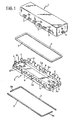
- the reference number 1 designates a tank designed to be fitted to an end manifold 2 of a heat exchanger (not illustrated), such as for instance a radiator.
- the tank 1 is made, for example, of glass-fibre-reinforced polyamide.
- the manifold 2 is instead made, for example, of metal material. It has, in a way of itself known, a main wall 2a (see Figure 1), in which there is made a plurality of openings 2b, to which the ends of the corresponding pipes of the heat exchanger are fixed, for example by means of brazing or mechanical expansion.
- the wall 2a of the manifold 2 has a basically rectangular shape and is surrounded by a perimetral border or rim 2c, which is integral therewith.
- each of the main sides of the manifold 2 from the rim 2c there extends a respective plurality of formations 4 set aligned to and at a distance from one another, basically shaped like hooks facing outwards.
- the hook formations 4 of the manifold 2 have the concavity facing downwards.
- the tank 1 has a basically rectangular border or rim and, along each of its main sides, in a position corresponding to the rim thereof that is to be coupled to the manifold, has a plurality of projecting formations 3 set aligned to and at a distance from one another.
- the above projecting formations 3 have on top a respective longitudinal furrow 3a.
- Said furrows 3a are basically aligned to one another.
- the tank 1 In a position corresponding to each smaller side, adjacent to the rim facing the manifold 2, the tank 1 has a further projecting formation 5 provided on top with a respective furrow 5a.
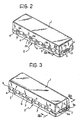
- the arrangement of the formations 3 and 5 of the tank 1 and of the formations 4 and 6 of the manifold 2 is such that the former can be interspersed with the latter when the tank 1 is fitted to the manifold 2 (see Figure 2) with interposition of an elastically compressible sealing gasket 7.
- FIG. 1 illustrates the tank 1 fitted to the manifold 2 on the gasket 7.
- each clamping member 9 is basically L-shaped, with a shorter branch 9a, designed to extend in a passage accordingly defined between the formation 5 of one side of the tank 1 and the corresponding formations 6 of the manifold 2.
- each formation 6 is conveniently folded downwards over the branch 9a of the clamping member 9, as illustrated in Figure 3, so as to block it in turn and prevent it from sliding out.
- the system described enables extremely fast and convenient unclamping and uncoupling of the tank 1 from the manifold 2. For this purpose, it is, in effect, simply necessary to raise the end tabs 6 of the manifold 2, and then, after compression of the tank-manifold assembly, slide out the clamping member or members 9.
- the formations 4 and 6 of the manifold could have a C-shaped or L-shaped profile and be folded towards the inside of the manifold instead of towards the outside.
Landscapes
- Engineering & Computer Science (AREA)
- Physics & Mathematics (AREA)
- Thermal Sciences (AREA)
- Mechanical Engineering (AREA)
- General Engineering & Computer Science (AREA)
- Heat-Exchange Devices With Radiators And Conduit Assemblies (AREA)
- Quick-Acting Or Multi-Walled Pipe Joints (AREA)
Applications Claiming Priority (2)
| Application Number | Priority Date | Filing Date | Title |
|---|---|---|---|
| IT2002TO000448A ITTO20020448A1 (it) | 2002-05-27 | 2002-05-27 | Sistema di accoppiamento e bloccaggio a tenuta di una vaschetta ad uncollettore di uno scambiatore di calore. |
| ITTO20020448 | 2002-05-27 |
Publications (1)
| Publication Number | Publication Date |
|---|---|
| EP1367352A1 true EP1367352A1 (en) | 2003-12-03 |
Family
ID=27639116
Family Applications (1)
| Application Number | Title | Priority Date | Filing Date |
|---|---|---|---|
| EP02027918A Withdrawn EP1367352A1 (en) | 2002-05-27 | 2002-12-13 | A system for sealed coupling and clamping of a tank to the manifold of a heat exchanger |
Country Status (5)
| Country | Link |
|---|---|
| EP (1) | EP1367352A1 (it) |
| AR (1) | AR038850A1 (it) |
| BR (1) | BR0300850A (it) |
| IT (1) | ITTO20020448A1 (it) |
| PL (1) | PL359253A1 (it) |
Cited By (3)
| Publication number | Priority date | Publication date | Assignee | Title |
|---|---|---|---|---|
| FR2867553A1 (fr) * | 2004-03-10 | 2005-09-16 | Valeo Thermique Moteur Sa | Boite collectrice d'echangeur de chaleur avec joint d'etancheite |
| CN109844441A (zh) * | 2016-10-14 | 2019-06-04 | 达纳加拿大公司 | 具有带有保持夹的旁通密封件的换热器 |
| LU505129B1 (en) * | 2023-09-18 | 2025-03-18 | Estra Automotive Systems Luxembourg S A R L | Heat exchanger |
Citations (2)
| Publication number | Priority date | Publication date | Assignee | Title |
|---|---|---|---|---|
| GB1303040A (it) * | 1969-07-22 | 1973-01-17 | ||
| US5845705A (en) * | 1995-11-13 | 1998-12-08 | Alliedsignal Inc. | Tank to header joint for heat exchangers |
-
2002
- 2002-05-27 IT IT2002TO000448A patent/ITTO20020448A1/it unknown
- 2002-12-13 EP EP02027918A patent/EP1367352A1/en not_active Withdrawn
-
2003
- 2003-02-27 AR ARP030100638A patent/AR038850A1/es unknown
- 2003-03-20 PL PL03359253A patent/PL359253A1/xx not_active Application Discontinuation
- 2003-03-27 BR BR0300850-9A patent/BR0300850A/pt not_active Application Discontinuation
Patent Citations (2)
| Publication number | Priority date | Publication date | Assignee | Title |
|---|---|---|---|---|
| GB1303040A (it) * | 1969-07-22 | 1973-01-17 | ||
| US5845705A (en) * | 1995-11-13 | 1998-12-08 | Alliedsignal Inc. | Tank to header joint for heat exchangers |
Cited By (5)
| Publication number | Priority date | Publication date | Assignee | Title |
|---|---|---|---|---|
| FR2867553A1 (fr) * | 2004-03-10 | 2005-09-16 | Valeo Thermique Moteur Sa | Boite collectrice d'echangeur de chaleur avec joint d'etancheite |
| WO2005088224A1 (fr) * | 2004-03-10 | 2005-09-22 | Valeo Systemes Thermiques | Boite collectrice d'echangeur de chaleur avec joint d'etancheite |
| CN109844441A (zh) * | 2016-10-14 | 2019-06-04 | 达纳加拿大公司 | 具有带有保持夹的旁通密封件的换热器 |
| LU505129B1 (en) * | 2023-09-18 | 2025-03-18 | Estra Automotive Systems Luxembourg S A R L | Heat exchanger |
| WO2025061772A1 (en) * | 2023-09-18 | 2025-03-27 | Estra Automotive Systems Luxembourg S.À R.L. | Heat exchanger |
Also Published As
| Publication number | Publication date |
|---|---|
| BR0300850A (pt) | 2004-08-17 |
| ITTO20020448A1 (it) | 2003-11-27 |
| ITTO20020448A0 (it) | 2002-05-27 |
| PL359253A1 (en) | 2003-12-01 |
| AR038850A1 (es) | 2005-01-26 |
Similar Documents
| Publication | Publication Date | Title |
|---|---|---|
| US4331201A (en) | Clamped connection | |
| US4338995A (en) | Radiant heating and cooling panel and method of manufacturing | |
| SE438722B (sv) | Klemforbindning samt anordning for framstellning av klemforbindningen | |
| GB2075173A (en) | Tube for tube-plate heat exchangers | |
| US20110180237A1 (en) | Welding a metal product | |
| EP1491840A3 (en) | Fastenerless mounting bracket for heat exchangers | |
| US7275587B2 (en) | Combination cooler module | |
| FR2711236B1 (fr) | Echangeur de chaleur à deux rangées de tubes, en particulier pour véhicule automobile. | |
| US5816321A (en) | Heat exchanger tank to be mounted in a heat exchanger and method of producing it | |
| US4350374A (en) | Header for solar-panels and a device for connecting header to panel | |
| EP1367352A1 (en) | A system for sealed coupling and clamping of a tank to the manifold of a heat exchanger | |
| GB1590032A (en) | Heat exchangers | |
| EP1195570A3 (en) | Tube for a heat exchanger and method of making same | |
| EP1059156A3 (en) | Equipment for moulding thermoplastic articles | |
| JP5503367B2 (ja) | サドル継手 | |
| ITMI962224A1 (it) | Scambiatore di calore in particolare per autoveicoli | |
| EP1239253A3 (en) | Heat exchanger | |
| CN203785506U (zh) | 一种改进型换热器用边板固定件 | |
| CN101466238B (zh) | 散热器 | |
| AU2001273931A1 (en) | Device and method for producing a catalyst with a monolith having a polygonal cross-section | |
| RU70351U1 (ru) | Радиатор | |
| US7024824B1 (en) | Entry port | |
| EP0797064A3 (en) | Heat-radiating element made of pressed steel plate and method for manufacturing it | |
| US20040211062A1 (en) | Method for producing a gasket | |
| DE29715601U1 (de) | Wärmetauscher, insbesondere als Heizungselement |
Legal Events
| Date | Code | Title | Description |
|---|---|---|---|
| PUAI | Public reference made under article 153(3) epc to a published international application that has entered the european phase |
Free format text: ORIGINAL CODE: 0009012 |
|
| AK | Designated contracting states |
Kind code of ref document: A1 Designated state(s): AT BE BG CH CY CZ DE DK EE ES FI FR GB GR IE IT LI LU MC NL PT SE SI SK TR |
|
| AX | Request for extension of the european patent |
Extension state: AL LT LV MK RO |
|
| AKX | Designation fees paid | ||
| REG | Reference to a national code |
Ref country code: DE Ref legal event code: 8566 |
|
| STAA | Information on the status of an ep patent application or granted ep patent |
Free format text: STATUS: THE APPLICATION IS DEEMED TO BE WITHDRAWN |
|
| 18D | Application deemed to be withdrawn |
Effective date: 20040604 |