EP1367585B1 - Dispositif a disque - Google Patents
Dispositif a disque Download PDFInfo
- Publication number
- EP1367585B1 EP1367585B1 EP02716426A EP02716426A EP1367585B1 EP 1367585 B1 EP1367585 B1 EP 1367585B1 EP 02716426 A EP02716426 A EP 02716426A EP 02716426 A EP02716426 A EP 02716426A EP 1367585 B1 EP1367585 B1 EP 1367585B1
- Authority
- EP
- European Patent Office
- Prior art keywords
- chassis
- guide rod
- pickup
- bracket
- compression spring
- Prior art date
- Legal status (The legal status is an assumption and is not a legal conclusion. Google has not performed a legal analysis and makes no representation as to the accuracy of the status listed.)
- Expired - Lifetime
Links
- 230000006835 compression Effects 0.000 claims description 18
- 238000007906 compression Methods 0.000 claims description 18
- 230000000881 depressing effect Effects 0.000 claims description 3
- 230000003287 optical effect Effects 0.000 description 6
- 230000001133 acceleration Effects 0.000 description 5
- 238000000034 method Methods 0.000 description 2
- 239000000853 adhesive Substances 0.000 description 1
- 230000001070 adhesive effect Effects 0.000 description 1
- 230000001419 dependent effect Effects 0.000 description 1
- 238000011161 development Methods 0.000 description 1
- 230000018109 developmental process Effects 0.000 description 1
- 230000007613 environmental effect Effects 0.000 description 1
- 230000002093 peripheral effect Effects 0.000 description 1
- 230000002269 spontaneous effect Effects 0.000 description 1
Images





Classifications
-
- G—PHYSICS
- G11—INFORMATION STORAGE
- G11B—INFORMATION STORAGE BASED ON RELATIVE MOVEMENT BETWEEN RECORD CARRIER AND TRANSDUCER
- G11B7/00—Recording or reproducing by optical means, e.g. recording using a thermal beam of optical radiation by modifying optical properties or the physical structure, reproducing using an optical beam at lower power by sensing optical properties; Record carriers therefor
- G11B7/08—Disposition or mounting of heads or light sources relatively to record carriers
-
- G—PHYSICS
- G11—INFORMATION STORAGE
- G11B—INFORMATION STORAGE BASED ON RELATIVE MOVEMENT BETWEEN RECORD CARRIER AND TRANSDUCER
- G11B7/00—Recording or reproducing by optical means, e.g. recording using a thermal beam of optical radiation by modifying optical properties or the physical structure, reproducing using an optical beam at lower power by sensing optical properties; Record carriers therefor
- G11B7/08—Disposition or mounting of heads or light sources relatively to record carriers
- G11B7/082—Aligning the head or the light source relative to the record carrier otherwise than during transducing, e.g. adjusting tilt set screw during assembly of head
-
- G—PHYSICS
- G11—INFORMATION STORAGE
- G11B—INFORMATION STORAGE BASED ON RELATIVE MOVEMENT BETWEEN RECORD CARRIER AND TRANSDUCER
- G11B21/00—Head arrangements not specific to the method of recording or reproducing
- G11B21/02—Driving or moving of heads
- G11B21/022—Programmed access in sequence to indexed parts of operating record carriers
- G11B21/025—Programmed access in sequence to indexed parts of operating record carriers of rotating discs
-
- G—PHYSICS
- G11—INFORMATION STORAGE
- G11B—INFORMATION STORAGE BASED ON RELATIVE MOVEMENT BETWEEN RECORD CARRIER AND TRANSDUCER
- G11B7/00—Recording or reproducing by optical means, e.g. recording using a thermal beam of optical radiation by modifying optical properties or the physical structure, reproducing using an optical beam at lower power by sensing optical properties; Record carriers therefor
- G11B7/08—Disposition or mounting of heads or light sources relatively to record carriers
- G11B7/085—Disposition or mounting of heads or light sources relatively to record carriers with provision for moving the light beam into, or out of, its operative position or across tracks, otherwise than during the transducing operation, e.g. for adjustment or preliminary positioning or track change or selection
- G11B7/0857—Arrangements for mechanically moving the whole head
- G11B7/08582—Sled-type positioners
-
- G—PHYSICS
- G11—INFORMATION STORAGE
- G11B—INFORMATION STORAGE BASED ON RELATIVE MOVEMENT BETWEEN RECORD CARRIER AND TRANSDUCER
- G11B7/00—Recording or reproducing by optical means, e.g. recording using a thermal beam of optical radiation by modifying optical properties or the physical structure, reproducing using an optical beam at lower power by sensing optical properties; Record carriers therefor
- G11B7/12—Heads, e.g. forming of the optical beam spot or modulation of the optical beam
- G11B7/22—Apparatus or processes for the manufacture of optical heads, e.g. assembly
Definitions
- the present invention relates to disk recording or playback devices having a tilt adjusting mechanism for tilting a pickup relative to the signal bearing surface of a disk.
- FIG. 12 is a perspective view of a conventional disk recording or playback device.
- a chassis 1 is provided thereon with a turntable 13 for placing a disk 7 thereon as is well known, and a pickup 2 movable toward or away from the turntable 13.
- the pickup 2 has an objective 22 on its upper surface and is movable as guided by two guide rods 4, 4 on the chassis 1.
- Each guide rod 4 has opposite ends fitting in respective brackets 9, 9 on the chassis 1.
- a motor M mounted on the chassis 1 at a side portion thereof is coupled by a gear mechanism 21 to a rack 20 provided on a side portion of the pickup 2.
- the motor M rotates gears of the gear mechanism 21 to move the pickup 2.
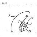
- FIG. 13 is a rear view of the disk 7.
- Pits 73, 73 are formed in the signal bearing surface of the disk 7 circumferentially thereof.
- the intensity of light reflected from the disk differs when the laser beam is projected on the pit 73 and when the laser beam is projected on a portion other than the pit 73. This reproduces a digital signal comprising 0 and 1.
- disks 7 adapted to record signals thereon at a high density. These disks are smaller in the spacing D between pits 73, 73 in the radial direction of the disk shown in FIG. 13.
- the optical axis of the laser beam slightly inclines relative to the signal bearing surface of the disk 7, it is likely that the signal can not be reproduced correctly since a pit 73 in a wrong position is irradiated with the beam.
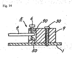
- FIG. 14 is a side elevation in section of an adjusting mechanism 5.
- the chassis 1 has provided thereon a bracket 9 having a recess 90 for one end of a guide rod 4 to fit in.
- the bracket 9 is fastened to the chassis 1 with a screw 30 driven into the chassis 1.
- a compression spring 50 for biasing the guide rod 4 upward is provided in the recess 90.
- An adjusting screw 6 is driven into the bracket 9 for depressing the guide rod 4 against the compression spring 50.
- the adjusting screw 6 is turned, the end of the guide rod 4 is moved upward or downward, so that the guide rod 4 tilts within a plane containing the direction of movement of the pickup 2 and orthogonal to the chassis 1. The tilt of the pickup 2 can be finely adjusted in this way.
- the prior art involves the likelihood that the bracket will deviate to move in a plane parallel to the chassis 1, i.e., in a horizontal plane, when the bracket 9 is fastened to the chassis 1 with the screw 30. Even if the tilt of the pickup 2 is accurately adjustable, the likelihood of the guide rod 4 deviating to move within a horizontal plane then makes it impossible for the pickup 2 to accurately move toward the center of the disk.
- JP-A-11224482 a disc recording device according to the preamble of claim 1 and claim 2 is disclosed. It comprises an adjusting mechanism in which a larger margin can be secured for environmental variations.
- the adjustment mechanism comprises a base, a pick-up head, a first guiding rod and a second guiding rod, guiding a movement of the pick-up head, being parallel to the each other and forming a plane with an orientation with respect to the disc that determines the angle of incidence of a laser beam, and at least three supports, each holding one end of the first and second guiding rods.
- Each of the supports comprises a main body, a spring and an adjusting screw. By adjusting the supports the orientation of the plane is adjusted.
- the disc player comprises an optical pickup, two guide shafts being disposed on opposite sides of the optical pickup for guiding the movement of the optical pickup, an adjustment system for adjusting the position of each guide shaft.
- JP 2001 023320 A a disc recording/reproducing device is disclosed. It comprises guide shafts for guiding a pickup and a screw shaft for adjusting the orientation.
- An object of the present invention is to accurately position a mechanism for adjusting the tilt of a pickup on a chassis, to prevent a guide rod from inadvertently deviating to move within a plane substantially parallel to the chassis and to give the device of the type described increased resistance to impact due, for example, to falling.
- FIG. 1 is a plan view of a disk recording or playback device.
- a turntable 13 for rotating a disk 7 is provided at a side portion of an opening 14 formed in a chassis 1, and a pickup 2 comprising an objective 22 for projecting a beam on the disk 7 is so disposed as to be movable toward or away from the turntable 13.
- the pickup 2 is fittingly mounted on guide rods 4, 4 each supported at opposite ends thereof by respective brackets 9, 9, and is designed to move on a phantom line L connecting the respective centers of the lens 22 and the turntable 13.
- a motor 17 is mounted on the chassis 1 laterally of the opening 14 and coupled to the pickup 2 by an intermediate gear 15. When energized, the motor 17 moves the pickup 2.
- the chassis 1 has outer peripheral edges, which are bent upward to provide upright walls 12, 12 fastened to a cabinet (not shown) disposed externally of the chassis 1.
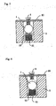
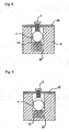
- FIGS. 2 and 3 are side elevations in section showing brackets 9 as seen from the direction A in FIG. 1.
- FIG. 2 shows the bracket of a first embodiment of the invention to be described later
- FIG. 3 shows the bracket of a second embodiment.
- the bracket 9 is fastened to the chassis 1 with a screw 30 driven into the bracket from below the chassis 1.
- the bracket 9 has a recess 90 for the end of the guide rod 4 to fit in, and a compression spring 50 for biasing the guide rod 4 upward is disposed in the recess 90.
- the top of the bracket 9 is covered with a bearing plate 80, which is fastened to the bracket 9 with a screw 85.
- An adjusting screw 6 is in screw-thread engagement with the bearing plate 80 and has a lower end in contact with the top of the guide rod 4. The arrangement is so designed that the direction of advance of the adjusting screw 6 is pointed toward the center C of the guide rod 4.
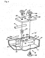
- FIG. 4 is an exploded perspective view of the bracket 9, guide rod 4 and bearing plate 80 according to the first embodiment of the invention, with the chassis 1 shown as partly broken away.
- the chassis 1 has an aperture 10 for the bracket 9 to partly fit in. Extending from the bracket 9 is a tongue 91 fitting in the aperture 10.
- the tongue 91 has an upper surface flush with the upper surface of the chassis 1. Thus, the tongue 91 is positioned below the guide rod 4.
- the tongue 91 has a circular-arc form and is in contact with an edge 11 of the chassis defining the aperture 10, whereby the bracket 9 is positioned in place in the plane of the chassis 1 with respect to horizontal directions.
- the recess 90 has a guide portion 93 with a width permitting the guide rod 4 to slightly loosely fit into the portion 93, and an accommodating portion 94 extending from the guide portion 93 in the form of a protuberant space and having the compression spring 50 fitted therein.
- a boss 95 Formed on the bottom surface of the recess 90 is a boss 95 having a diameter slightly smaller than the inside diameter of the compression spring 50.
- the boss 95 has a height not permitting the pickup 2 to contact the chassis 1 when the guide rod 4 is brought into contact with the boss 95.
- FIG. 7 is an exploded perspective view of the bracket 9, guide rod 4 and bearing plate 80 according to the second embodiment of the invention, with a chassis 1 shown as partly broken away.
- the chassis 1 has an aperture 10 for the bracket 9 to partly fit in. Extending from the bracket 9 is a tongue 91 fitting in the aperture 10.
- the tongue 91 has an upper surface flush with the upper surface of the chassis 1.
- the tongue 91 is positioned below the guide rod 4.
- the tongue 91 has a circular-arc form and is in contact with an edge 11 of the chassis defining the aperture 10, whereby the bracket 9 is positioned in place with respect to horizontal directions in the plane of the chassis 1.
- a recess 90 has a guide portion 93 with a width permitting the guide rod 4 to slightly loosely fit into the portion 93, and an accommodating portion 94 extending from the guide portion 93 in the form of a protuberant space and having a compression spring 50 fitted therein.
- the guide portion 93 of the bracket 9 is provided with a wall 96 having a cutout for the guide rod 4 to fit in.
- the wall 96 has a height not permitting the contact of the pickup 2 with the chassis 1 when the guide rod 4 is brought into contact with the wall.
- the top wall of the bracket 9 has positioning projections 92, 92a fittable into the bearing plate 80, and a screw bore 82 positioned at one side of the arrangement of projections 92, 92a for driving a plate fastening screw 85 thereinto.
- the bearing plate 80 is provided with cutouts 81, 81 for the respective positioning projections 92, 92a to fit in. Formed in the bearing plate 80 at opposite sides of the cutouts 81, 81 are a screw hole 82 for the adjusting screw 6 to be driven in, and a hole 83 for the plate fastening screw 85 to be inserted through.
- the bracket 9 is attached to the chassis 1 by the following procedure.
- FIG. 10 is a rear view of the chassis 1.
- the chassis 1 is turned upside down, and the bracket 9 is inserted into the aperture 10 from below the chassis 1.
- the bracket 9 is fixed to a jig 98 to restrain the bracket 9 from turning in a horizontal plane.
- the fastening screw 30 is driven into the bracket 9 through the chassis 1.
- the screw 30 turns clockwise by tightening up, so that when the head of the screw 30 comes into contact with the chassis 1, the chassis 1 turns clockwise due to the friction between the chassis and the head of the screw 30.
- the aperture-defining edge 11 comes into contact with the tongue 91, whereby the bracket 9 is positioned in place on the chassis 1. Since the tongue 91 has a circular-arc form, the tongue 91 invariably comes into contact with one point on the edge 11 for positioning.
- the tongue 91 of the bracket 9 and the edge 11 provide the first positioning means 3.
- the bracket 9 is positioned in place on the chassis 1 simultaneously when the bracket 9 is fastened with the screw 30. This saves time and labor in positioning.
- the chassis 1 is turned downside up, the bearing plate 80 is placed over the bracket 9 having the compression spring 50 and guide rod 4 inserted therein, and the plate fastening screw 85 is driven through the hole 83 into the screw bore 82 in the bracket 9.
- the screw 85 is turned clockwise by tightening up, and when the head of the screw 85 comes into contact with the bearing plate 80, the plate 80 turns clockwise due to the friction between the plate and the head of the screw 85.
- FIG. 11 which is a plan view of the bearing plate 80
- the cutout portion 81 on the clockwise side comes into contact with the positioning projection 92, whereby the plate 80 is positioned in place in a plane parallel to the plane of the chassis 1.
- the positioning projection 92 and the cutout 81 in the bearing plate 80 provide the second positioning means 8.
- the bearing plate 80 is positioned in place within a plane substantially parallel to the chassis 1 simultaneously when the plate 80 is fastened with the screw 85. This saves time and labor in positioning the plate.
- the guide rod 4 When the adjusting screw 6 is turned after the bracket 9 has been attached, the guide rod 4 has its tilt adjusted in a plane containing the direction of movement of the pickup 2 and orthogonal to the chassis 1.
- FIG. 5 is a view in section taken along a plane containing the line C-C in FIG. 4.
- the direction of advance of the adjusting screw 6 is pointed toward the center C of the guide rod 4 by positioning the bearing plate 80 in place within a plane parallel to the plane of the chassis 1.
- the direction of advance of the adjusting screw 6 swerves from the center C of the guide rod 4.
- there is a small clearance in the guide portion 93 of the recess 90 around the guide rod 4 whereas if the direction of advance of the adjusting screw 6 deviates from the center C of the guide rod 4, the adjusting screw 6 pushes the rod 4 at an eccentric portion, permitting the guide rod 4 to laterally deviate in a direction orthogonal to the rod 4 within the range of the clearance.
- the path of movement of the pickup 2 then deflects from a phantom line L extending toward the center of the disk as shown in FIG. 1. Accordingly, accurately pointing the direction of advance of the adjusting screw 6 toward the center C of the guide rod 4 restrains the rod 4 from laterally deviating toward a direction orthogonal to the rod 4 within the guide portion 93.
- the guide rod 4 is prevented from inadvertently deviating and moving within a plane substantially parallel to the chassis 1 and precluded from shifting or deforming due to an impact, for example, of falling of the device.
- the boss 95 and the wall 96 have a height lower than the desired tilt adjusting range and not permitting the pickup 2 to contact the chassis 1 when the guide rod 4 is brought into intimate contact with the boss or the wall.
- the desired tilt adjusting range is such a range that makes it possible to absorb, for example, the error involved in mounting the pickup 2 and the distortion of the chassis 1, and to mount the pickup 2 in place with predetermined accuracy relative to the disk surface
- the guide rod 4 is held between the adjusting screw 6 and the compression spring 50 by being pushed up by the force of the spring at all times during tilt adjustment, and is highly responsive to the tightening or loosening turn of the adjusting screw 6 to ensure accurate tilt adjustment.
- the adjusting screw 6 After the adjustment of tilt, the adjusting screw 6 is locked with an adhesive and thereby prevented from loosening through spontaneous turning.
- the guide rod 4 By virtue of the pushing-up force of the compression spring 50, the guide rod 4 remains at an unaltered level to accurately maintain the adjusted tilt angle even if subjected to some vibration or like disturbance from outside, obviating the likelihood that the tilt angle of the pickup will vary.
- the device For example if the user allowed the device to fall off the desk down onto the floor in an error, the device is subjected to acceleration of as great as 100 G, possible causing the pickup 2 to collide with the chassis 1 depending on the direction of fall.
- the pickup 2 is a precision optical system comprising an assembly of many small parts, is therefore susceptible to impact and becomes no longer operable for normal recording or playback if the optical system is distorted by colliding with the chassis 1 with 100 G.
- the bracket 9 can be mounted as accurately positioned on the chassis 1 by the first positioning means 3. This eliminates the likelihood that the guide rod 4 will deviate or move in a plane parallel to the chassis 1.
- the direction of advance of the adjusting screw 6 is pointed toward the center C of the guide rod 4 by the second positioning means 8.
- the height of the compression spring 50 as fully compressed is lower than the tilt adjusting range, and when the guide rod 43 is positioned on the spring 50 of compressed height, the pickup 2 is held out of contact with the chassis 1. Accordingly, the guide rod 4 is held between the adjusting screw 6 and the compression spring 50 by being pushed up by the force of the spring at all times during tilt adjustment, and is highly responsive to the tightening or loosening turn of the adjusting screw 6 to ensure accurate tilt adjustment.
- the guide rod 4 comes to a halt at the level of the boss 95 or wall 96, so that when the guide rod 4 moves from the adjusted position to this level due to impact, the repulsive force of the compression spring 50 attenuates the acceleration, and the deflection of the guide rod 4 absorbs the impact to greatly reduce the acceleration and mitigate the impact unlike the case wherein the pickup 2 collides directly with the chassis 1.
- the boss 95 and the wall 96 are given a height not permitting the pickup 2 to contact the chassis 1 when the guide rod 4 is brought into contact with the boss 95 or the wall 96, whereby the pickup can be protected from impact.
Landscapes
- Moving Of Heads (AREA)
- Moving Of The Head For Recording And Reproducing By Optical Means (AREA)
Claims (3)
- Dispositif d'enregistrement ou de lecture de disque comprenant un phonocapteur (2) disposé sur un châssis (1) et pouvant s'approcher ou s'éloigner du centre d'un disque (7), une tige-guide (4) s'étendant dans le sens du mouvement du phonocapteur (2) et ayant le phonocapteur fixé sur sa circonférence, et un mécanisme de réglage (5) pour modifier l'angle d'inclinaison de la tige-guide (4) dans un plan contenant la direction du mouvement du phonocapteur (2) et perpendiculaire à une surface supérieure du châssis (1), le mécanisme de réglage (5) comprenant un support (9) pour tenir une extrémité de la tige-guide (4), un ressort de compression (50) pour dévier la tige-guide (4) et une vis de réglage (6) pour appuyer la tige-guide (4) contre le ressort de compression (50),
caractérisé en ce qu'une partie de logement (94) du support (9) est pourvue d'un bossage (95) placé à l'intérieur du ressort de compression (50) et ayant une hauteur inférieure à la plage de réglage de l'inclinaison, le phonocapteur (2) étant placé à un niveau où il n'est pas en contact avec le châssis (1) quand la tige-guide (4) est placée contre le bossage (95),
dans lequel une languette (91) qui s'étend à partir du support (9) rentre dans une ouverture (10) du châssis (1),
la languette (91) étant en contact avec un bord (11) de l'ouverture (10), moyennant quoi le support (9) est maintenu en place par rapport aux directions horizontales dans le plan du châssis (1). - Dispositif d'enregistrement ou de lecture de disque comprenant un phonocapteur (2) disposé sur un châssis (1) et pouvant s'approcher ou s'éloigner du centre d'un disque (7), une tige-guide (4) s'étendant dans le sens du mouvement du phonocapteur (2) et ayant le phonocapteur fixé sur sa circonférence, et un mécanisme de réglage (5) pour modifier l'angle d'inclinaison de la tige-guide (4) dans un plan contenant la direction du mouvement du phonocapteur (2) et perpendiculaire à la surface supérieure du châssis (1), le mécanisme de réglage (5) comprenant un support (9) pour tenir une extrémité de la tige-guide (4), un ressort de compression (50) pour dévier la tige-guide (4) et une vis de réglage (6) pour appuyer la tige-guide (4) contre le ressort de compression (50),
une partie guide (93) du support (9) étant pourvue d'une paroi (96) ayant une hauteur inférieure à la plage de réglage de l'inclinaison, le phonocapteur (2) étant placé à un niveau où il n'est pas en contact avec le châssis (1) quand la tige-guide (4) repose sur la paroi (96),
caractérisé en ce qu'une languette (91) qui s'étend à partir du support (9) rentre dans une ouverture (10) du châssis (1),
la languette (91) étant en contact avec un bord (11) de l'ouverture (10), moyennant quoi le support (9) est maintenue en place par rapport aux directions horizontales dans le plan du châssis (1). - Dispositif d'enregistrement ou de lecture de disque selon la revendication (1) ou (2), caractérisé en ce que le mécanisme de réglage (5) comprend un premier moyen de positionnement (3) pour mettre le support (9) sur le châssis (1) et un second moyen de positionnement (8) pour placer la vis de réglage (6) dans un plan sensiblement parallèle à la surface du châssis (1) et orienter avec précision la direction de progression de la vis de réglage (6) vers le centre (C) de la tige-guide (4).
Applications Claiming Priority (3)
| Application Number | Priority Date | Filing Date | Title |
|---|---|---|---|
| JP2001023060 | 2001-01-31 | ||
| JP2001023060A JP2002230922A (ja) | 2001-01-31 | 2001-01-31 | ピックアップ傾き調整機構を有するディスク記録又は再生装置 |
| PCT/JP2002/000616 WO2002061748A1 (fr) | 2001-01-31 | 2002-01-28 | Dispositif a disque |
Publications (3)
| Publication Number | Publication Date |
|---|---|
| EP1367585A1 EP1367585A1 (fr) | 2003-12-03 |
| EP1367585A4 EP1367585A4 (fr) | 2004-05-12 |
| EP1367585B1 true EP1367585B1 (fr) | 2006-03-22 |
Family
ID=18888389
Family Applications (1)
| Application Number | Title | Priority Date | Filing Date |
|---|---|---|---|
| EP02716426A Expired - Lifetime EP1367585B1 (fr) | 2001-01-31 | 2002-01-28 | Dispositif a disque |
Country Status (7)
| Country | Link |
|---|---|
| US (1) | US20040052199A1 (fr) |
| EP (1) | EP1367585B1 (fr) |
| JP (1) | JP2002230922A (fr) |
| KR (1) | KR20030075168A (fr) |
| CN (1) | CN1280823C (fr) |
| DE (1) | DE60210053D1 (fr) |
| WO (1) | WO2002061748A1 (fr) |
Cited By (1)
| Publication number | Priority date | Publication date | Assignee | Title |
|---|---|---|---|---|
| KR101422410B1 (ko) | 2013-06-11 | 2014-08-13 | 세메스 주식회사 | 오버 핸드 이송 장치용 수평 지그 |
Families Citing this family (13)
| Publication number | Priority date | Publication date | Assignee | Title |
|---|---|---|---|---|
| JP4111681B2 (ja) * | 2001-02-19 | 2008-07-02 | 三洋電機株式会社 | ピックアップ傾き調整機構を有するディスク記録又は再生装置 |
| TW543906U (en) * | 2002-01-25 | 2003-07-21 | Lite On It Corp | Inclining angle adjusting device for compact disk drive |
| JP2004071018A (ja) * | 2002-08-05 | 2004-03-04 | Pioneer Electronic Corp | ピックアップのスキュー調整機構 |
| US7342849B2 (en) * | 2003-01-31 | 2008-03-11 | Sony Corporation | Recording and/or playback device |
| KR20040083852A (ko) * | 2003-03-25 | 2004-10-06 | 엘지전자 주식회사 | 광디스크 드라이브의 스큐조정장치 |
| CN2636359Y (zh) * | 2003-05-24 | 2004-08-25 | 鸿富锦精密工业(深圳)有限公司 | 光学记录/再现装置 |
| JP2005267775A (ja) * | 2004-03-19 | 2005-09-29 | Orion Denki Kk | 光ピックアップユニットの衝撃吸収構造を備えたディスク装置 |
| JP2005317133A (ja) * | 2004-04-28 | 2005-11-10 | Sony Corp | ディスクドライブユニット及びディスク記録及び/又は再生装置 |
| CN1322499C (zh) * | 2004-09-29 | 2007-06-20 | 常州市新科精密机械有限公司 | 光盘读取装置的光拾取器驱动装置 |
| TWI303416B (en) * | 2004-09-30 | 2008-11-21 | Asustek Comp Inc | Electronic apparatus and optical pickup head tilting angle adjusting structure thereof |
| JP2006155781A (ja) * | 2004-11-30 | 2006-06-15 | Orion Denki Kk | ガイドシャフト保持機構及びそのガイドシャフト保持機構を備えたディスク装置 |
| TW200632891A (en) * | 2005-03-01 | 2006-09-16 | Liteo On It Corp | Structure for positioning a shaft carrying an optical pick-up unit |
| JP4843350B2 (ja) | 2006-04-04 | 2011-12-21 | 株式会社日立製作所 | ディスク駆動装置 |
Family Cites Families (12)
| Publication number | Priority date | Publication date | Assignee | Title |
|---|---|---|---|---|
| JP2747332B2 (ja) * | 1989-07-05 | 1998-05-06 | 三菱電機株式会社 | 光ヘッド |
| US6116273A (en) * | 1994-12-06 | 2000-09-12 | Cummins Engine Company, Inc. | Fuel metering check valve arrangement for a time-pressure controlled unit fuel injector |
| KR100224829B1 (ko) * | 1996-07-10 | 1999-10-15 | 윤종용 | 광디스크 드라이브 |
| KR100243191B1 (ko) * | 1996-07-25 | 2000-02-01 | 윤종용 | 광 기록 재생 장치 |
| US5993408A (en) * | 1997-10-03 | 1999-11-30 | Allergan Sales, Inc. | Thin tip phaco needle |
| US5982735A (en) * | 1997-12-29 | 1999-11-09 | Industrial Technology Research Institute | Tilt angle adjustable mechanism for compact disc recording/reproducing device |
| JPH11224482A (ja) * | 1998-02-04 | 1999-08-17 | Matsushita Electric Ind Co Ltd | 記録再生装置 |
| JP2000057715A (ja) * | 1998-08-05 | 2000-02-25 | Pioneer Electron Corp | ディスクプレーヤ |
| US6415105B1 (en) * | 1999-05-21 | 2002-07-02 | Asahi Kogaku Kogyo Kabushiki Kaisha | Image stabilizer |
| JP2001023320A (ja) * | 1999-07-09 | 2001-01-26 | Sanyo Electric Co Ltd | ディスク記録再生装置 |
| JP3668097B2 (ja) * | 2000-03-17 | 2005-07-06 | 三洋電機株式会社 | ピックアップ傾き調整機構を有するディスク記録又は再生装置 |
| TW547752U (en) * | 2001-03-22 | 2003-08-11 | Benq Corp | Guiding rod device of CD drive |
-
2001
- 2001-01-31 JP JP2001023060A patent/JP2002230922A/ja active Pending
-
2002
- 2002-01-28 EP EP02716426A patent/EP1367585B1/fr not_active Expired - Lifetime
- 2002-01-28 KR KR10-2003-7010033A patent/KR20030075168A/ko not_active Withdrawn
- 2002-01-28 WO PCT/JP2002/000616 patent/WO2002061748A1/fr not_active Ceased
- 2002-01-28 DE DE60210053T patent/DE60210053D1/de not_active Expired - Lifetime
- 2002-01-28 CN CNB028043154A patent/CN1280823C/zh not_active Expired - Fee Related
- 2002-01-28 US US10/466,555 patent/US20040052199A1/en not_active Abandoned
Cited By (1)
| Publication number | Priority date | Publication date | Assignee | Title |
|---|---|---|---|---|
| KR101422410B1 (ko) | 2013-06-11 | 2014-08-13 | 세메스 주식회사 | 오버 핸드 이송 장치용 수평 지그 |
Also Published As
| Publication number | Publication date |
|---|---|
| KR20030075168A (ko) | 2003-09-22 |
| EP1367585A4 (fr) | 2004-05-12 |
| CN1531733A (zh) | 2004-09-22 |
| EP1367585A1 (fr) | 2003-12-03 |
| DE60210053D1 (de) | 2006-05-11 |
| CN1280823C (zh) | 2006-10-18 |
| US20040052199A1 (en) | 2004-03-18 |
| JP2002230922A (ja) | 2002-08-16 |
| WO2002061748A1 (fr) | 2002-08-08 |
Similar Documents
| Publication | Publication Date | Title |
|---|---|---|
| EP1367585B1 (fr) | Dispositif a disque | |
| US6704270B2 (en) | Disk recording or playback device having mechanism for adjusting tilt of pickup | |
| US6667945B2 (en) | Disk drive device | |
| EP0978825B1 (fr) | Lecteur de disques | |
| US20040017766A1 (en) | Optical disk apparatus with pickup tilt adjusting mechanism and entertainment apparatus | |
| JP3035223B2 (ja) | ディスクプレーヤのピックアップ位置調整装置 | |
| US6324152B1 (en) | Disc reproducing apparatus with motor base bearing system | |
| WO2002067259A1 (fr) | Dispositif d'enregistrement ou de lecture de disque avec mecanisme de lecture a reglage d'inclinaison | |
| EP1098323B1 (fr) | Caméscope à disque optique | |
| JP2001307438A (ja) | 板ばね機構とディスクドライブ装置 | |
| JP3702150B2 (ja) | ピックアップ傾き調整機構を有するディスク記録又は再生装置 | |
| JP2005050398A (ja) | ピックアップ傾き調整機構を具えたディスク記録又は再生装置 | |
| JP3874902B2 (ja) | ディスク再生装置 | |
| JP2002230923A (ja) | ピックアップ傾き調整機構を有するディスク記録又は再生装置 | |
| JP2001344767A (ja) | ピックアップ傾き調整機構を有するディスク記録又は再生装置 | |
| JP3342390B2 (ja) | ディスク記録再生装置 | |
| KR100604781B1 (ko) | 픽업 기울기 조정장치 | |
| JP3691354B2 (ja) | ピックアップ傾き調整機構を有するディスク記録又は再生装置及びその調整機構を位置決めする方法 | |
| KR20010024092A (ko) | 디스크 재생 장치 | |
| US20090249379A1 (en) | Optical pickup feed device | |
| JP3490937B2 (ja) | ディスク記録又は再生装置 | |
| JP2002100129A (ja) | 光ディスクドライブ装置 | |
| JP2003187539A (ja) | ディスク記録又は再生装置 | |
| KR19990009629U (ko) | 광 디스크 플레이어의 스핀들모터 스큐 조정장치 | |
| JP2001307405A (ja) | ディスクドライブ装置 |
Legal Events
| Date | Code | Title | Description |
|---|---|---|---|
| PUAI | Public reference made under article 153(3) epc to a published international application that has entered the european phase |
Free format text: ORIGINAL CODE: 0009012 |
|
| 17P | Request for examination filed |
Effective date: 20030826 |
|
| AK | Designated contracting states |
Kind code of ref document: A1 Designated state(s): DE FR GB |
|
| RIC1 | Information provided on ipc code assigned before grant |
Ipc: 7G 11B 21/02 B Ipc: 7G 11B 7/085 A |
|
| A4 | Supplementary search report drawn up and despatched |
Effective date: 20040324 |
|
| 17Q | First examination report despatched |
Effective date: 20040617 |
|
| GRAP | Despatch of communication of intention to grant a patent |
Free format text: ORIGINAL CODE: EPIDOSNIGR1 |
|
| GRAS | Grant fee paid |
Free format text: ORIGINAL CODE: EPIDOSNIGR3 |
|
| GRAA | (expected) grant |
Free format text: ORIGINAL CODE: 0009210 |
|
| AK | Designated contracting states |
Kind code of ref document: B1 Designated state(s): DE FR GB |
|
| REG | Reference to a national code |
Ref country code: GB Ref legal event code: FG4D |
|
| REF | Corresponds to: |
Ref document number: 60210053 Country of ref document: DE Date of ref document: 20060511 Kind code of ref document: P |
|
| PG25 | Lapsed in a contracting state [announced via postgrant information from national office to epo] |
Ref country code: DE Free format text: LAPSE BECAUSE OF FAILURE TO SUBMIT A TRANSLATION OF THE DESCRIPTION OR TO PAY THE FEE WITHIN THE PRESCRIBED TIME-LIMIT Effective date: 20060623 |
|
| PLBE | No opposition filed within time limit |
Free format text: ORIGINAL CODE: 0009261 |
|
| STAA | Information on the status of an ep patent application or granted ep patent |
Free format text: STATUS: NO OPPOSITION FILED WITHIN TIME LIMIT |
|
| 26N | No opposition filed |
Effective date: 20061227 |
|
| EN | Fr: translation not filed | ||
| PG25 | Lapsed in a contracting state [announced via postgrant information from national office to epo] |
Ref country code: FR Free format text: LAPSE BECAUSE OF FAILURE TO SUBMIT A TRANSLATION OF THE DESCRIPTION OR TO PAY THE FEE WITHIN THE PRESCRIBED TIME-LIMIT Effective date: 20070309 |
|
| PG25 | Lapsed in a contracting state [announced via postgrant information from national office to epo] |
Ref country code: FR Free format text: LAPSE BECAUSE OF FAILURE TO SUBMIT A TRANSLATION OF THE DESCRIPTION OR TO PAY THE FEE WITHIN THE PRESCRIBED TIME-LIMIT Effective date: 20060322 |
|
| PGFP | Annual fee paid to national office [announced via postgrant information from national office to epo] |
Ref country code: GB Payment date: 20100202 Year of fee payment: 9 |
|
| GBPC | Gb: european patent ceased through non-payment of renewal fee |
Effective date: 20110128 |
|
| PG25 | Lapsed in a contracting state [announced via postgrant information from national office to epo] |
Ref country code: GB Free format text: LAPSE BECAUSE OF NON-PAYMENT OF DUE FEES Effective date: 20110128 |