EP1367672B1 - Eine geformte Dipolantenne für eine oder zwei Polarisationen mit integrierter Speisung - Google Patents
Eine geformte Dipolantenne für eine oder zwei Polarisationen mit integrierter Speisung Download PDFInfo
- Publication number
- EP1367672B1 EP1367672B1 EP03012117A EP03012117A EP1367672B1 EP 1367672 B1 EP1367672 B1 EP 1367672B1 EP 03012117 A EP03012117 A EP 03012117A EP 03012117 A EP03012117 A EP 03012117A EP 1367672 B1 EP1367672 B1 EP 1367672B1
- Authority
- EP
- European Patent Office
- Prior art keywords
- dipole
- antenna
- arms
- feeding structure
- cable
- Prior art date
- Legal status (The legal status is an assumption and is not a legal conclusion. Google has not performed a legal analysis and makes no representation as to the accuracy of the status listed.)
- Expired - Lifetime
Links
- 230000009977 dual effect Effects 0.000 title description 17
- 239000004020 conductor Substances 0.000 claims abstract description 18
- 239000004033 plastic Substances 0.000 claims abstract description 7
- XAGFODPZIPBFFR-UHFFFAOYSA-N aluminium Chemical compound [Al] XAGFODPZIPBFFR-UHFFFAOYSA-N 0.000 claims abstract description 6
- 229910052782 aluminium Inorganic materials 0.000 claims abstract description 6
- 239000000463 material Substances 0.000 claims abstract description 6
- 230000010287 polarization Effects 0.000 claims description 32
- 238000004519 manufacturing process Methods 0.000 claims description 9
- 238000000034 method Methods 0.000 claims description 5
- 238000007747 plating Methods 0.000 claims description 4
- 229910000842 Zamak Inorganic materials 0.000 claims description 3
- 239000007769 metal material Substances 0.000 claims description 3
- 229910001369 Brass Inorganic materials 0.000 claims 1
- 239000010951 brass Substances 0.000 claims 1
- 238000002955 isolation Methods 0.000 abstract description 13
- RYGMFSIKBFXOCR-UHFFFAOYSA-N Copper Chemical compound [Cu] RYGMFSIKBFXOCR-UHFFFAOYSA-N 0.000 abstract description 3
- 238000010276 construction Methods 0.000 abstract description 3
- 229910052802 copper Inorganic materials 0.000 abstract description 3
- 239000010949 copper Substances 0.000 abstract description 3
- 238000000465 moulding Methods 0.000 abstract description 2
- 239000012212 insulator Substances 0.000 description 4
- 238000010295 mobile communication Methods 0.000 description 4
- 230000005540 biological transmission Effects 0.000 description 3
- 230000008878 coupling Effects 0.000 description 3
- 238000010168 coupling process Methods 0.000 description 3
- 238000005859 coupling reaction Methods 0.000 description 3
- 230000005855 radiation Effects 0.000 description 3
- 238000003491 array Methods 0.000 description 2
- 238000004891 communication Methods 0.000 description 2
- 239000004810 polytetrafluoroethylene Substances 0.000 description 2
- 229920001343 polytetrafluoroethylene Polymers 0.000 description 2
- 229910000679 solder Inorganic materials 0.000 description 2
- 229910000906 Bronze Inorganic materials 0.000 description 1
- BQCADISMDOOEFD-UHFFFAOYSA-N Silver Chemical compound [Ag] BQCADISMDOOEFD-UHFFFAOYSA-N 0.000 description 1
- 229910052770 Uranium Inorganic materials 0.000 description 1
- 238000004458 analytical method Methods 0.000 description 1
- 238000013459 approach Methods 0.000 description 1
- 239000010974 bronze Substances 0.000 description 1
- 238000005266 casting Methods 0.000 description 1
- 238000007796 conventional method Methods 0.000 description 1
- KUNSUQLRTQLHQQ-UHFFFAOYSA-N copper tin Chemical compound [Cu].[Sn] KUNSUQLRTQLHQQ-UHFFFAOYSA-N 0.000 description 1
- 238000013461 design Methods 0.000 description 1
- 230000000694 effects Effects 0.000 description 1
- PCHJSUWPFVWCPO-UHFFFAOYSA-N gold Chemical compound [Au] PCHJSUWPFVWCPO-UHFFFAOYSA-N 0.000 description 1
- 229910052737 gold Inorganic materials 0.000 description 1
- 239000010931 gold Substances 0.000 description 1
- 239000011810 insulating material Substances 0.000 description 1
- 238000012986 modification Methods 0.000 description 1
- 230000004048 modification Effects 0.000 description 1
- 229910052709 silver Inorganic materials 0.000 description 1
- 239000004332 silver Substances 0.000 description 1
- 229910052720 vanadium Inorganic materials 0.000 description 1
Images




Classifications
-
- H—ELECTRICITY
- H01—ELECTRIC ELEMENTS
- H01Q—ANTENNAS, i.e. RADIO AERIALS
- H01Q21/00—Antenna arrays or systems
-
- H—ELECTRICITY
- H01—ELECTRIC ELEMENTS
- H01Q—ANTENNAS, i.e. RADIO AERIALS
- H01Q21/00—Antenna arrays or systems
- H01Q21/06—Arrays of individually energised antenna units similarly polarised and spaced apart
- H01Q21/061—Two dimensional planar arrays
- H01Q21/062—Two dimensional planar arrays using dipole aerials
-
- H—ELECTRICITY
- H01—ELECTRIC ELEMENTS
- H01Q—ANTENNAS, i.e. RADIO AERIALS
- H01Q1/00—Details of, or arrangements associated with, antennas
- H01Q1/12—Supports; Mounting means
- H01Q1/22—Supports; Mounting means by structural association with other equipment or articles
- H01Q1/24—Supports; Mounting means by structural association with other equipment or articles with receiving set
- H01Q1/241—Supports; Mounting means by structural association with other equipment or articles with receiving set used in mobile communications, e.g. GSM
- H01Q1/246—Supports; Mounting means by structural association with other equipment or articles with receiving set used in mobile communications, e.g. GSM specially adapted for base stations
-
- H—ELECTRICITY
- H01—ELECTRIC ELEMENTS
- H01Q—ANTENNAS, i.e. RADIO AERIALS
- H01Q21/00—Antenna arrays or systems
- H01Q21/0087—Apparatus or processes specially adapted for manufacturing antenna arrays
-
- H—ELECTRICITY
- H01—ELECTRIC ELEMENTS
- H01Q—ANTENNAS, i.e. RADIO AERIALS
- H01Q21/00—Antenna arrays or systems
- H01Q21/06—Arrays of individually energised antenna units similarly polarised and spaced apart
- H01Q21/08—Arrays of individually energised antenna units similarly polarised and spaced apart the units being spaced along or adjacent to a rectilinear path
-
- H—ELECTRICITY
- H01—ELECTRIC ELEMENTS
- H01Q—ANTENNAS, i.e. RADIO AERIALS
- H01Q21/00—Antenna arrays or systems
- H01Q21/24—Combinations of antenna units polarised in different directions for transmitting or receiving circularly and elliptically polarised waves or waves linearly polarised in any direction
-
- H—ELECTRICITY
- H01—ELECTRIC ELEMENTS
- H01Q—ANTENNAS, i.e. RADIO AERIALS
- H01Q9/00—Electrically-short antennas having dimensions not more than twice the operating wavelength and consisting of conductive active radiating elements
- H01Q9/04—Resonant antennas
- H01Q9/16—Resonant antennas with feed intermediate between the extremities of the antenna, e.g. centre-fed dipole
- H01Q9/28—Conical, cylindrical, cage, strip, gauze, or like elements having an extended radiating surface; Elements comprising two conical surfaces having collinear axes and adjacent apices and fed by two-conductor transmission lines
-
- H—ELECTRICITY
- H01—ELECTRIC ELEMENTS
- H01Q—ANTENNAS, i.e. RADIO AERIALS
- H01Q9/00—Electrically-short antennas having dimensions not more than twice the operating wavelength and consisting of conductive active radiating elements
- H01Q9/04—Resonant antennas
- H01Q9/44—Resonant antennas with a plurality of divergent straight elements, e.g. V-dipole, X-antenna; with a plurality of elements having mutually inclined substantially straight portions
Definitions
- the present invention generally relates to dual polarized panel base-station antennae for use in mobile communication systems. More specifically, the invention relates to the structure of dipoles used with dual polarized panel base-station antennae.
- Dipole antennae are common in the communications industry, and conventional structures, including half-wavelength dipoles with "bow tie” structures and “butterfly” structures, are described in several books, including Banalis, Constantine A., “Antenna Theory Analysis and Design", Wiley, 1997.
- panel base-station antennae such as those used in mobile communication systems, rely heavily on dual polarization antennae.
- these antennae are constructed using single linear polarized elements, grouped in such a way that creates dual polarization. In this case, two separate arrays of radiating elements are required to radiate on both polarizations.
- Feeding signals to and from these dual polarization structures is usually accomplished by conventional coupling structures such as coaxial cables, microstrip or stripline transmission lines, or slits.
- conventional coupling structures such as coaxial cables, microstrip or stripline transmission lines, or slits.
- the drawback to using these conventional coupling structures with the antennae and dipoles described above is that they increase the number of parts needed to construct the antenna, thereby generating undesired intermodulation distortions.
- the dipoles in the antenna array it is also important for the dipoles in the antenna array to have a good impedance so that all of the dipoles in the array can be properly matched.
- the present invention provides a new and useful single or dual polarized antenna for use in mobile communication systems.
- a first embodiment of the invention provides a polarized antenna for use in a mobile communication system comprising at least one dipole having a base portion and a plurality of radiating arms extending therefrom, wherein said dipole is formed as a single structure; and a reflector plate to which the base portion is attached, said reflector plate being a ground plane and reflecting polarized radio frequency signals.
- the dipole may include two sets of arms, including a first set and a second set respectively having a first polarization and a second polarization corresponding to two polarizations of said dipole.
- Each set of arms preferably includes two pairs of arms arranged in a V-shape and having a vertex portion.
- a first pair of arms in each set has a first slot at said vertex portion and a second pair of arms has a second slot at said vertex portion for receiving a feed cable, said first slot receiving a cable center conductor and said second slot receiving an insulating jacket.
- the dipole can also include a cavity for feeding the cable located at the vertex portion of the arms.
- the present invention further provides a method of manufacturing a dipole for use in a polarized antenna, comprising forming an entire dipole body as a single piece, including a base portion and a plurality of radiating arms.
- the dipole body is optimally molded from a conventional material such as plastic, aluminum or the like.
- the method of the present invention further comprises plating the molded dipole body with a metallic material that can be soldered.
- the invention comprises the features of construction, combination of elements and arrangement of parts which will be exemplified in the construction hereinafter set forth, and the scope of the invention will be indicated in the claims.
- FIG 1 is a perspective view of an antenna using an array of dipoles.
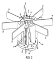
- FIG 2 is a perspective view of the dual polarization dipole (all parts assembled).
- FIG 3 is a top view of the dual polarization dipole shown in FIG 2 .
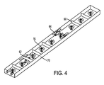
- FIG 4 is a view of an embodiment of an antenna using an array of dipoles having a variety of RF isolation devices.
- FIG 5 is a plot of three radiation patterns of the first polarization having beamwidths of 65.4 degrees at 1.71 GHz, 62.2 degrees at 1.8 GHz and 60.5 degrees at 1.88 GHz respectively for a 1 * 9 antenna array using the subject matter of the invention shown in FIG 4 .
- FIG 6 is a plot of three radiation patterns for the second polarization of a 1 * 9 arrayed antenna using the subject matter of the invention shown in FIG 4 .
- Figure 1 shows a dual polarization antenna 14 of the present invention with a 1x9 array of dipoles 16 according to the present invention.
- the antenna 14 comprises the array of dipoles 16 and a reflector plate 12 to which the dipoles 16 are attached.
- the invention is not limited to a particular array.
- FIG. 2 shows a dipole 16 of the present invention in greater detail.
- the dipole 16 is formed as a unitary structure including the base portion, arms, and feeding structures discussed below.
- the forming of the dipole can be accomplished by conventional methods, such as molding, casting, or carving.
- the dipole can be formed using conventional materials such as copper, bronze, plastic, aluminum, or zamak. If the material used is a type that cannot be soldered, such as plastic or aluminum, then the dipole, once formed, can be covered or plated, in part or in whole, with a metallic material that can be soldered, such as copper, silver, or gold.
- the dipole 16 includes four pairs of arms 18, 20, 22, and 24 attached to a base portion 26.
- the arms are arranged in pairs 18, 20, 22, and 24 each having a V- or U-shape, with the arms radiating outward from the vertex portion 21 of the V or U.
- the base portion 26 of the dipole attaches to the reflector plate 12 shown in Figure 1.
- the pairs of arms are arranged such that pair 18 is opposite pair 20, and pair 22 is opposite pair 24.
- the opposing pairs are wired and positioned with respect to the reflector plate 14 so as to transmit and/or receive RF energy at two polarizations: a first polarization of +45 degrees and a second polarization of -45 degrees.
- Opposing pairs 20 and 18 correspond to the first and second polarization of the antenna 14, respectively.
- opposing pairs 24 and 22 correspond to the first and second polarizations.
- the dipole of the present invention is not limited to these polarizations, and it is understood that changing the number, arrangement and position of the arm pairs can change both the number of polarizations and the polarization angles of the antenna.
- Each set of opposing pairs of arms includes a feeding structure 28 which is located at the vertex portion 21 of one of the arm pairs.
- This feeding structure 28 is a longitudinal cavity 23 running the length of the dipole body, allowing a cable 30 to be fed into the base portion 26 of the dipole, through the feeding structure, and out to the top of the dipole.
- a slot, discussed below, is placed in the vertex of the opposite arm pair. The conductor of the cable is soldered to this vertex via this slot.
- FIG. 2 and Figure 3 show the relationship of these pairs of arms in greater detail. Focusing on a single arm set, including arm pairs 22 and 24, the feeding structure 28 is defined by the cavity 23 that is provided in the vertex portion of one of the arms 22 of the pair. The cable 30 passes through the cavity 23.
- This feeding structure 28 also includes a slotted aperture 32 that extends along the cavity and has a width m. The slotted aperture 32 exposes the insulating jacket 34 of the cable 30 running through the cavity 23.
- Each arm set also includes first and second slots 31 and 38, respectively, through which the cable is further fed.
- the first slot 31 is located at the vertex portion of a first pair of arms 22 and the second slot 38 is formed at the vertex portion of the second set of arms 24.
- the cable is run such that the first slot 31 retains the entire cable (i.e., unstripped) and the second slot 38 retains the conductor portion 36 of the cable.
- the conductor 36 is then soldered to the vertex portion 21 of the second set of arms 24 proximate the second slot 38.
- the arm set including arm pairs 18 and 20 is arranged in a similar fashion.
- the vertex portion 21 of the pair of arms 18 includes a feeding structure 28 through which is defined by the cavity 23, through which a second cable 42 is passed.
- This feeding structure 28 also includes a slotted aperture 44 that extends along the cavity 23 and has a width m. The slotted aperture 44 exposes the insulating jacket 46 of the cable 42 running through the cavity 23.
- Arm sets 18 and 20 also include first and second slots 47 and 50, respectively, through which the cable is further fed.
- the first slot 47 is located at the vertex portion 21 of the first pair of arms 18 and the second slot 50 is formed at the vertex portion 21 of the second set of arms 20.
- the cable is run such that the first slot 47 retains the entire cable (i.e., unstripped) and the second slot 50 retains the conductor portion 48 of the cable 42.
- the conductor 48 is then soldered to the vertex portion 21 of the second set of arms 20 proximate the second slot 50.
- This dipole structure allows the use of simple coaxial cables to serve as feed cables 30 and 42, as discussed above.
- These coaxial cables typically include an inner conductor surrounded by an insulator of PTFE or similar material.
- the dipole and its internal feeding structure allows these cables 42 and 30 to directly pass through the body of the dipole 16 to the top and connect to the arm pairs 20, 18 and 24, 22 at slots 50 and 38, respectively, without needing any grommets to insulate the conductors 36 and 48 from the conductive base portion 26 to which the arms 20 or 24 are attached. This reduces the overall number of parts needed to build the dipole, thereby lowering the manufacturing cost and improving the RF performance of the antenna.
- the signal performance of the dipole 16 can be further improved by placing conventional insulating separators 37 between adjacent arm pairs.
- These separators can be made of conventional insulating materials such as plastic or PTFE.
- the impedance of the dipole is determined by the sizes of the apertures, the center conductor of the cable, and the holes in the base portion 26 extending into the cavities 28, these sizes can be chosen to provide the dipole with a desired impedance as well as to facilitate the forming and plating of the dipole.
- the size of these apertures can be made wide enough to ensure proper plating of the molded piece, but narrow enough to allow the dipole to provide good port-to-port isolation, good impedance, and good pattern purity. The scope of the invention is not intended to be limited to any particular shape of these apertures.
- the characteristic impedance Zo can be readily estimated as follows.
- the impedance, Zo can be calculated by the following equation
- D is the diameter of the holes in the base portion 26 and the longitudinal cavities 28
- d is the diameter of the cable's center conductor
- ⁇ r is the dielectric constant of the cable insulator used.
- D is the diameter of the holes in the base portion 26 and the longitudinal cavities 28, d is the diameter of the cable's center conductor, ⁇ is the angle at which the aperture is slanted, and er is the dielectric constant of the cable insulator used.
- the characteristic impedance Zo can be approximated by the equation:
- h is the radius of the longitudinal cavities
- d is the diameter of the cable's center conductor
- ⁇ r is the dielectric constant of the cable insulator used.
- the molded dipole of the present invention can be used in a variety of antenna configurations.
- the base portion 26 of the molded dipole can be designed and shaped to match a complimentary form on the reflector plate 12 so as to further facilitate the assembly of the antenna array. It would be obvious to one skilled in the art that the size and shape of the base portion can vary from antenna to antenna and still be within the scope of the invention.
- the present invention also provides for the isolation of inputs of a dipole 16 in antenna arrays that include a plurality of dipoles of the present invention.
- Dipoles 16 in the dual polarization antenna 14 can be isolated from each other using conventional radio frequency isolation devices, such as walls, H structures and I structures.
- Figure 4 shows a dual polarization antenna 70 in which the dipoles 16 are isolated using a number of different isolation devices including walls 60, H isolators 62, and I isolators 64. It is understood that the dipole of the present invention can be used in conjunction with ordinary isolation devices and structures.
- Figures 5-6 show the performance characteristics of the antenna array shown in Figure 4.
- Figures 5 and 6 show a plot of three radiation patterns of the first and second polarizations of the antenna array of Figure 4 using dipoles 16 of the present invention. As shown, the antenna exhibits good port-to-port isolation of less than 30 dB at a variety of beamwidths and at high frequencies.
Landscapes
- Engineering & Computer Science (AREA)
- Computer Networks & Wireless Communication (AREA)
- Manufacturing & Machinery (AREA)
- Variable-Direction Aerials And Aerial Arrays (AREA)
- Aerials With Secondary Devices (AREA)
- Details Of Aerials (AREA)
- Waveguide Aerials (AREA)
Claims (18)
- Polarisierte Antenne (14), beinhaltend
mindestens einen Dipol (16) mit einem Unterteil (26) und mehreren von dort ausgehenden Strahlungszweigen (18, 20, 22, 24), wobei ein erstes Paar (22) besagter zweige einen Scheitelpunktteil (21) mit einem ersten Schlitz (31) zur Aufnahme einer Isolierhülse (34) eines Speisekabels (30) hat und ein zweites Paar (24) besagter zweige einen Scheitelpunktteil (21) mit einem zweiten Schlitz (38) zur Aufnahme eines Kabel-Mittelleiters (36) des Speisekabels (30) hat, ferner eine Speisestruktur (28) mit einer Apertur (32) einer vorgegebenen Breite (m) und eine Reflektorplatte (12), an welcher das Unterteil (26) befestigt ist, wobei die Reflektorplatte (12) eine Massefläche ist und polarisierte Hochfrequenzsignale reflektiert. - Antenne (14) gemäß Anspruch 1, wobei der besagte Dipol (16) ein als Formteil ausgeführter Dipol ist.
- Antenne (14) gemäß Anspruch 2, wobei der besagte Dipol (16) aus Kunststoff, Aluminium, Messing oder einer Zamak-Legierung besteht.
- Antenne (14) gemäß Anspruch 3, wobei der besagte Dipol (16) zumindest teilweise mit einem lötfähigen Beschichtungsmaterial überzogen ist.
- Antenne (14) gemäß Anspruch 1, wobei die besagten mehreren Strahlungszweige (18, 20, 22, 24) in zwei Gruppen unterteilt sind, bestehend aus einer ersten Gruppe (18, 20) und einer zweiten Gruppe (22, 24), die jeweils eine erste Polarisation beziehungsweise eine zweite Polarisation haben, welche zwei Polarisationen des besagten Dipols (16) entsprechen.
- Antenne (14) gemäß Anspruch 5, wobei jede der besagten ersten und zweiten Gruppen von Zweigen zwei Zweigpaare beinhalten, die in V-Form angeordnet sind und einen Scheitelpunktteil (21) aufweisen.
- Antenne (14) gemäß Anspruch 1, wobei der besagte Dipol (16) eine darin angeordnete Speisestruktur (28) aufweist,
wobei die besagte Speisestruktur (28) eine Apertur (32) der Breite m aufweist, und wobei der besagte Dipol (16) eine Speiseöffnung im besagten Unterteil (26) des Dipols (16) aufweist, durch welche hindurch ein Speisekabel (30) in die besagte Speisestruktur (28) verlaufen kann, wobei die besagte Öffnung einen Durchmesser D hat, und wobei das besagte Kabel (30) einen Mittelleiter (36) mit einem Durchmesser d aufweist. - Antenne (14) gemäß Anspruch 7, wobei die Impedanz des Dipols (16) eine Funktion des Innenleiter-Durchmessers (d) und des Durchmessers (D) der besagten Speiseöffnung ist.
- Antenne (14) gemäß Anspruch 7, wobei die besagte Speisestruktur (28) einen Radius (h) hat und die Aperturbreite (m) kleiner als der Durchmesser (2h) der besagten Speisestruktur (28) ist.
- Antenne (14) gemäß Anspruch 9, wobei die Impedanz des Dipols (16) eine Funktion des Innenleiter-Durchmessers (d) und des Radius der besagten Speisestruktur (28) ist.
- Antenne (14) gemäß Anspruch 1, ferner beinhaltend ein Isolierelement (37), das zwischen den besagten Zweigen (18, 20, 22, 24) angeordnet ist.
- Verfahren zum Herstellen eines für den Einsatz in einer polarisierten Antenne (14) vorgesehenen Dipols (16), beinhaltend die Schritte,
einen Dipolkörper als einzelnes Teil zu formen, wobei der besagte Dipolkörper ein Unterteil (26) und mehrere von dort ausgehende Strahlungszweige (18, 20, 22, 24) besitzt, wobei ein erstes Paar (22) besagter zweige einen Scheitelpunktteil (21) mit einem ersten Schlitz (31) hat, wobei ein zweites Paar (24) besagter Zweige einen Scheitelpunktteil (21) mit einem zweiten Schlitz (38) hat und wobei der besagte zweite Schlitz (38) kleiner als der besagte erste Schlitz (31) ist. - Verfahren gemäß Anspruch 12, wobei die besagten mehreren Strahlungszweige (18, 20, 22, 24) in zwei Gruppen unterteilt sind, bestehend aus einer ersten Gruppe (18, 20) und einer zweiten Gruppe (22, 24), die jeweils eine erste Polarisation beziehungsweise eine zweite Polarisation haben, welche zwei Polarisationen des besagten Dipols (16) entsprechen.
- Verfahren gemäß Anspruch 12, wobei der besagte Dipol (16) eine darin angeordnete Speisestruktur (28) aufweist,
wobei die besagte Speisestruktur (28) eine Apertur (32) der Breite m aufweist, und wobei der besagte Dipol (16) eine Speiseöffnung im besagten Unterteil (26) des Dipols (16) aufweist, durch welche hindurch ein Speisekabel (30) in die besagte Speisestruktur (28) verlaufen kann, wobei die besagte Öffnung einen Durchmesser D hat, und wobei das besagte Kabel (30) einen Mittelleiter (36) mit einem Durchmesser d aufweist. - Verfahren zum Herstellen eines Dipols (16) gemäß Anspruch 12, wobei der besagte Dipolkörper als Formteil ausgeführt ist.
- Verfahren zum Herstellen eines Dipols (16) gemäß Anspruch 15, wobei der besagte Dipolkörper ein Formteil aus Kunststoff, Aluminium oder einer Zamak-Legierung ist.
- Verfahren gemäß Anspruch 12, ferner beinhaltend den Schritt, zumindest einen Teil des Dipolkörper-Formteils mit einem metallischen Material zu beschichten.
- Verfahren gemäß Anspruch 12, ferner beinhaltend einen Schritt, ein Isolierelement (37) vorzusehen, das zwischen den besagten zweigen (18, 20, 22, 24) angeordnet ist.
Applications Claiming Priority (2)
| Application Number | Priority Date | Filing Date | Title |
|---|---|---|---|
| US10/157,838 US6747606B2 (en) | 2002-05-31 | 2002-05-31 | Single or dual polarized molded dipole antenna having integrated feed structure |
| US157838 | 2002-05-31 |
Publications (2)
| Publication Number | Publication Date |
|---|---|
| EP1367672A1 EP1367672A1 (de) | 2003-12-03 |
| EP1367672B1 true EP1367672B1 (de) | 2006-06-28 |
Family
ID=29419656
Family Applications (1)
| Application Number | Title | Priority Date | Filing Date |
|---|---|---|---|
| EP03012117A Expired - Lifetime EP1367672B1 (de) | 2002-05-31 | 2003-05-30 | Eine geformte Dipolantenne für eine oder zwei Polarisationen mit integrierter Speisung |
Country Status (8)
| Country | Link |
|---|---|
| US (1) | US6747606B2 (de) |
| EP (1) | EP1367672B1 (de) |
| KR (1) | KR101056310B1 (de) |
| CN (1) | CN1462089B (de) |
| AT (1) | ATE332019T1 (de) |
| AU (1) | AU2003204333B2 (de) |
| BR (1) | BRPI0302034B1 (de) |
| DE (1) | DE60306457T2 (de) |
Cited By (1)
| Publication number | Priority date | Publication date | Assignee | Title |
|---|---|---|---|---|
| CN105977652A (zh) * | 2016-07-07 | 2016-09-28 | 京信通信技术(广州)有限公司 | 双频阵列天线 |
Families Citing this family (40)
| Publication number | Priority date | Publication date | Assignee | Title |
|---|---|---|---|---|
| US7280082B2 (en) * | 2003-10-10 | 2007-10-09 | Cisco Technology, Inc. | Antenna array with vane-supported elements |
| ATE390731T1 (de) * | 2004-02-20 | 2008-04-15 | Alcatel Lucent | Dualpolarisiertes antennenmodul |
| SE527757C2 (sv) * | 2004-07-28 | 2006-05-30 | Powerwave Technologies Sweden | En reflektor, en antenn som använder en reflektor och en tillverkningsmetod för en reflektor |
| EP1667278A1 (de) * | 2004-11-23 | 2006-06-07 | Alcatel | Antenne einer Basisstation mit dualpolarisierten Strahlerelementen und geformtem Reflektor |
| MXPA06003617A (es) * | 2005-04-25 | 2007-02-02 | Rymsa | Antena de cavidad excitada con uno o varios dipolos. |
| US20080231528A1 (en) * | 2005-04-25 | 2008-09-25 | Ramon Guixa Arderiu | Cavity Antenna Excited with One or Several Dipoles |
| WO2007011295A1 (en) * | 2005-07-22 | 2007-01-25 | Powerwave Technologies Sweden Ab | Antenna arrangement with interleaved antenna elements |
| FI120522B (fi) * | 2006-03-02 | 2009-11-13 | Filtronic Comtek Oy | Uudenlainen antennirakenne ja menetelmä sen valmistamiseksi |
| US7864130B2 (en) * | 2006-03-03 | 2011-01-04 | Powerwave Technologies, Inc. | Broadband single vertical polarized base station antenna |
| KR100708542B1 (ko) | 2006-12-13 | 2007-04-18 | 장유규 | 이종 재질을 이용한 복사 소자 및 이종 재질의 복사 소자를이용한 안테나 |
| WO2008109173A1 (en) * | 2007-03-08 | 2008-09-12 | Powerwave Technologies, Inc. | Dual staggered vertically polarized variable azimuth beamwidth antenna for wireless network |
| WO2008124027A1 (en) * | 2007-04-06 | 2008-10-16 | Powerwave Technologies, Inc. | Dual stagger off settable azimuth beam width controlled antenna for wireless network |
| US7948441B2 (en) | 2007-04-12 | 2011-05-24 | Raytheon Company | Low profile antenna |
| EP2165388B1 (de) * | 2007-06-13 | 2018-01-17 | Intel Corporation | Strahlbreitengesteuerte antenne mit dreifach-staffelungs-versetzbarem azimut für ein drahtloses netz |
| US7688265B2 (en) * | 2007-09-18 | 2010-03-30 | Raytheon Company | Dual polarized low profile antenna |
| US7710343B2 (en) * | 2007-10-16 | 2010-05-04 | Hong Kong Technologies Group Limited | Compact 3-port orthogonally polarized MIMO antennas |
| US8508427B2 (en) | 2008-01-28 | 2013-08-13 | P-Wave Holdings, Llc | Tri-column adjustable azimuth beam width antenna for wireless network |
| US9270017B2 (en) * | 2008-02-04 | 2016-02-23 | Agc Automotive Americas R&D, Inc. | Multi-element cavity-coupled antenna |
| EP2226890A1 (de) * | 2009-03-03 | 2010-09-08 | Hitachi Cable, Ltd. | Mobile Kommunikationsbasisstationsantenne |
| CN101877434A (zh) * | 2009-04-28 | 2010-11-03 | 华为技术有限公司 | 一种偶极子天线单元及其制造方法 |
| FR2946805B1 (fr) * | 2009-06-11 | 2012-03-30 | Alcatel Lucent | Element rayonnant d'antenne |
| US8547280B2 (en) | 2010-07-14 | 2013-10-01 | Raytheon Company | Systems and methods for exciting long slot radiators of an RF antenna |
| CN102025023A (zh) * | 2010-12-09 | 2011-04-20 | 广东通宇通讯股份有限公司 | 一种宽频宽波束双极化天线单元 |
| EP2710668B1 (de) * | 2011-05-02 | 2019-07-31 | CommScope Technologies LLC | Dreipoliges antennenelement und gruppenantenne |
| US9325057B2 (en) * | 2011-11-02 | 2016-04-26 | Alcatel Lucent | Antenna radiating element |
| WO2016078475A1 (zh) | 2014-11-18 | 2016-05-26 | 李梓萌 | 小型化双极化基站天线 |
| US9843108B2 (en) | 2014-07-25 | 2017-12-12 | Futurewei Technologies, Inc. | Dual-feed dual-polarized antenna element and method for manufacturing same |
| US9917363B1 (en) | 2014-11-14 | 2018-03-13 | Sprint Communications Company L.P. | Adjustable cross-polarized antenna array elements |
| US10148012B2 (en) * | 2015-02-13 | 2018-12-04 | Commscope Technologies Llc | Base station antenna with dummy elements between subarrays |
| KR101703741B1 (ko) | 2015-09-11 | 2017-02-07 | 주식회사 케이엠더블유 | 다중편파 방사소자 및 이를 구비한 안테나 |
| EP3280006A1 (de) | 2016-08-03 | 2018-02-07 | Li, Zimeng | Doppelt polarisierte antenne |
| US10641867B2 (en) | 2016-08-15 | 2020-05-05 | Magna Electronics Inc. | Vehicle radar system with shaped radar antennas |
| EP3535806B1 (de) * | 2016-12-06 | 2021-07-28 | Huawei Technologies Co., Ltd. | Zweibandantennenelement und basisstation |
| CN107887713B (zh) * | 2017-10-19 | 2021-03-30 | 深圳市飞荣达科技股份有限公司 | 集成电路天线振子及其制作方法 |
| US11103925B2 (en) * | 2018-03-22 | 2021-08-31 | The Boeing Company | Additively manufactured antenna |
| CN108539434B (zh) * | 2018-04-17 | 2024-08-09 | 昆山恩电开通信设备有限公司 | 一种超宽带辐射单元 |
| CN109980329B (zh) * | 2019-03-12 | 2023-12-26 | 广州司南技术有限公司 | 一种宽带双极化天线 |
| DE102019108901A1 (de) | 2019-03-22 | 2020-09-24 | Telefonaktiebolaget Lm Ericsson (Publ) | Antennenanordnung für Mobilfunksysteme mit zumindest einem dual-polarisierten Kreuzdipol |
| US11909110B2 (en) | 2020-09-30 | 2024-02-20 | The Boeing Company | Additively manufactured mesh horn antenna |
| US12244069B2 (en) * | 2022-06-07 | 2025-03-04 | Aeroantenna Technology, Inc. | Cross dipole circularly polarized antenna |
Family Cites Families (23)
| Publication number | Priority date | Publication date | Assignee | Title |
|---|---|---|---|---|
| US4613868A (en) | 1983-02-03 | 1986-09-23 | Ball Corporation | Method and apparatus for matched impedance feeding of microstrip-type radio frequency antenna structure |
| US4543583A (en) | 1983-06-06 | 1985-09-24 | Gerard A. Wurdack & Associates, Inc. | Dipole antenna formed of coaxial cable |
| GB2191043A (en) | 1986-05-28 | 1987-12-02 | Gen Electric Co Plc | Dipole array |
| US5726666A (en) | 1996-04-02 | 1998-03-10 | Ems Technologies, Inc. | Omnidirectional antenna with single feedpoint |
| US6298386B1 (en) | 1996-08-14 | 2001-10-02 | Emc Corporation | Network file server having a message collector queue for connection and connectionless oriented protocols |
| US6182157B1 (en) | 1996-09-19 | 2001-01-30 | Compaq Computer Corporation | Flexible SNMP trap mechanism |
| AU730484B2 (en) | 1997-07-03 | 2001-03-08 | Alcatel | Dual polarized cross bow tie antenna with airline feed |
| FR2766626B1 (fr) * | 1997-07-28 | 1999-10-01 | Alsthom Cge Alcatel | Systeme d'antennes directionnelles a polarisation croisee |
| US5982336A (en) | 1997-08-01 | 1999-11-09 | Transystems, Inc. | Structure of super integrated down converter (SIDC) with dual band mechanical and notch filters |
| US6127986A (en) | 1998-01-02 | 2000-10-03 | Transystem, Inc. | Integrated down-converter with dipole-antenna implemented with novel mechanical filter structure |
| US6072439A (en) | 1998-01-15 | 2000-06-06 | Andrew Corporation | Base station antenna for dual polarization |
| JP3707233B2 (ja) | 1998-02-26 | 2005-10-19 | ブラザー工業株式会社 | ネットワークアダプタ及びこれを備えた端末システム |
| US6085237A (en) | 1998-05-01 | 2000-07-04 | Cisco Technology, Inc. | User-friendly interface for setting expressions on an SNMP agent |
| US6272131B1 (en) | 1998-06-11 | 2001-08-07 | Synchrodyne Networks, Inc. | Integrated data packet network using a common time reference |
| US6292829B1 (en) | 1998-07-15 | 2001-09-18 | Nortel Networks Limited | Method and device for network management |
| US6034649A (en) * | 1998-10-14 | 2000-03-07 | Andrew Corporation | Dual polarized based station antenna |
| US6211840B1 (en) * | 1998-10-16 | 2001-04-03 | Ems Technologies Canada, Ltd. | Crossed-drooping bent dipole antenna |
| US6253243B1 (en) | 1998-12-04 | 2001-06-26 | Sun Microsystems, Inc. | Automated trap control for a distributed network management system |
| DE19860121A1 (de) | 1998-12-23 | 2000-07-13 | Kathrein Werke Kg | Dualpolarisierter Dipolstrahler |
| US6300912B1 (en) | 2000-03-07 | 2001-10-09 | Antenna World, Inc. | Compact mountable dipole antenna |
| US6529172B2 (en) * | 2000-08-11 | 2003-03-04 | Andrew Corporation | Dual-polarized radiating element with high isolation between polarization channels |
| US6307510B1 (en) | 2000-10-31 | 2001-10-23 | Harris Corporation | Patch dipole array antenna and associated methods |
| US20060025798A1 (en) * | 2004-02-23 | 2006-02-02 | Cook Timothy C | Method and apparatus for fecal continence |
-
2002
- 2002-05-31 US US10/157,838 patent/US6747606B2/en not_active Expired - Lifetime
-
2003
- 2003-05-22 AU AU2003204333A patent/AU2003204333B2/en not_active Expired
- 2003-05-29 BR BRPI0302034A patent/BRPI0302034B1/pt not_active IP Right Cessation
- 2003-05-30 EP EP03012117A patent/EP1367672B1/de not_active Expired - Lifetime
- 2003-05-30 KR KR1020030034571A patent/KR101056310B1/ko not_active Expired - Lifetime
- 2003-05-30 AT AT03012117T patent/ATE332019T1/de not_active IP Right Cessation
- 2003-05-30 CN CN031385168A patent/CN1462089B/zh not_active Expired - Lifetime
- 2003-05-30 DE DE60306457T patent/DE60306457T2/de not_active Expired - Lifetime
Cited By (2)
| Publication number | Priority date | Publication date | Assignee | Title |
|---|---|---|---|---|
| CN105977652A (zh) * | 2016-07-07 | 2016-09-28 | 京信通信技术(广州)有限公司 | 双频阵列天线 |
| CN105977652B (zh) * | 2016-07-07 | 2019-05-31 | 京信通信技术(广州)有限公司 | 双频阵列天线 |
Also Published As
| Publication number | Publication date |
|---|---|
| BRPI0302034B1 (pt) | 2016-09-27 |
| ATE332019T1 (de) | 2006-07-15 |
| EP1367672A1 (de) | 2003-12-03 |
| AU2003204333A1 (en) | 2003-12-18 |
| DE60306457T2 (de) | 2007-07-05 |
| BR0302034A (pt) | 2004-08-24 |
| CN1462089A (zh) | 2003-12-17 |
| KR101056310B1 (ko) | 2011-08-11 |
| US20030222830A1 (en) | 2003-12-04 |
| AU2003204333B2 (en) | 2008-09-04 |
| DE60306457D1 (de) | 2006-08-10 |
| US6747606B2 (en) | 2004-06-08 |
| CN1462089B (zh) | 2010-05-12 |
| KR20030094023A (ko) | 2003-12-11 |
Similar Documents
| Publication | Publication Date | Title |
|---|---|---|
| US6747606B2 (en) | Single or dual polarized molded dipole antenna having integrated feed structure | |
| EP2272128B1 (de) | Breitbandige dielektrische notch-strahlerantenne mit hohem gewinn | |
| US4843403A (en) | Broadband notch antenna | |
| US6424311B1 (en) | Dual-fed coupled stripline PCB dipole antenna | |
| US6028562A (en) | Dual polarized slotted array antenna | |
| US4443802A (en) | Stripline fed hybrid slot antenna | |
| US5581266A (en) | Printed-circuit crossed-slot antenna | |
| US6337666B1 (en) | Planar sleeve dipole antenna | |
| KR100207600B1 (ko) | 공진기 부착형 마이크로스트립 다이폴 안테나 어레이 | |
| US4853704A (en) | Notch antenna with microstrip feed | |
| AU742085B2 (en) | Microstrip array antenna | |
| US6317094B1 (en) | Feed structures for tapered slot antennas | |
| US5070340A (en) | Broadband microstrip-fed antenna | |
| US6313798B1 (en) | Broadband microstrip antenna having a microstrip feedline trough formed in a radiating element | |
| US6091366A (en) | Microstrip type antenna device | |
| US5818397A (en) | Circularly polarized horizontal beamwidth antenna having binary feed network with microstrip transmission line | |
| US7256750B1 (en) | E-plane omni-directional antenna | |
| JP2023505332A (ja) | 高電流保護を備えた無指向性水平偏波アンテナ | |
| GB2424765A (en) | Dipole antenna with an impedance matching arrangement | |
| EP0487053A1 (de) | Antenne | |
| CN116670935A (zh) | 天线装置 | |
| EP3796472B1 (de) | Dipolantennenvorrichtung und verfahren zur herstellung | |
| EP0826250B1 (de) | Antenne mit zwei strahlerelementen mit einer einstellbaren phasendifferenz zwischen den strahlerelementen |
Legal Events
| Date | Code | Title | Description |
|---|---|---|---|
| PUAI | Public reference made under article 153(3) epc to a published international application that has entered the european phase |
Free format text: ORIGINAL CODE: 0009012 |
|
| AK | Designated contracting states |
Kind code of ref document: A1 Designated state(s): AT BE BG CH CY CZ DE DK EE ES FI FR GB GR HU IE IT LI LU MC NL PT RO SE SI SK TR |
|
| AX | Request for extension of the european patent |
Extension state: AL LT LV MK |
|
| 17P | Request for examination filed |
Effective date: 20040126 |
|
| 17Q | First examination report despatched |
Effective date: 20040616 |
|
| AKX | Designation fees paid |
Designated state(s): AT BE BG CH CY CZ DE DK EE ES FI FR GB GR HU IE IT LI LU MC NL PT RO SE SI SK TR |
|
| GRAP | Despatch of communication of intention to grant a patent |
Free format text: ORIGINAL CODE: EPIDOSNIGR1 |
|
| GRAS | Grant fee paid |
Free format text: ORIGINAL CODE: EPIDOSNIGR3 |
|
| GRAA | (expected) grant |
Free format text: ORIGINAL CODE: 0009210 |
|
| AK | Designated contracting states |
Kind code of ref document: B1 Designated state(s): AT BE BG CH CY CZ DE DK EE ES FI FR GB GR HU IE IT LI LU MC NL PT RO SE SI SK TR |
|
| PG25 | Lapsed in a contracting state [announced via postgrant information from national office to epo] |
Ref country code: NL Free format text: LAPSE BECAUSE OF FAILURE TO SUBMIT A TRANSLATION OF THE DESCRIPTION OR TO PAY THE FEE WITHIN THE PRESCRIBED TIME-LIMIT Effective date: 20060628 Ref country code: BE Free format text: LAPSE BECAUSE OF FAILURE TO SUBMIT A TRANSLATION OF THE DESCRIPTION OR TO PAY THE FEE WITHIN THE PRESCRIBED TIME-LIMIT Effective date: 20060628 Ref country code: FI Free format text: LAPSE BECAUSE OF FAILURE TO SUBMIT A TRANSLATION OF THE DESCRIPTION OR TO PAY THE FEE WITHIN THE PRESCRIBED TIME-LIMIT Effective date: 20060628 Ref country code: AT Free format text: LAPSE BECAUSE OF FAILURE TO SUBMIT A TRANSLATION OF THE DESCRIPTION OR TO PAY THE FEE WITHIN THE PRESCRIBED TIME-LIMIT Effective date: 20060628 Ref country code: SK Free format text: LAPSE BECAUSE OF FAILURE TO SUBMIT A TRANSLATION OF THE DESCRIPTION OR TO PAY THE FEE WITHIN THE PRESCRIBED TIME-LIMIT Effective date: 20060628 Ref country code: RO Free format text: LAPSE BECAUSE OF FAILURE TO SUBMIT A TRANSLATION OF THE DESCRIPTION OR TO PAY THE FEE WITHIN THE PRESCRIBED TIME-LIMIT Effective date: 20060628 Ref country code: LI Free format text: LAPSE BECAUSE OF FAILURE TO SUBMIT A TRANSLATION OF THE DESCRIPTION OR TO PAY THE FEE WITHIN THE PRESCRIBED TIME-LIMIT Effective date: 20060628 Ref country code: CZ Free format text: LAPSE BECAUSE OF FAILURE TO SUBMIT A TRANSLATION OF THE DESCRIPTION OR TO PAY THE FEE WITHIN THE PRESCRIBED TIME-LIMIT Effective date: 20060628 Ref country code: SI Free format text: LAPSE BECAUSE OF FAILURE TO SUBMIT A TRANSLATION OF THE DESCRIPTION OR TO PAY THE FEE WITHIN THE PRESCRIBED TIME-LIMIT Effective date: 20060628 Ref country code: CH Free format text: LAPSE BECAUSE OF FAILURE TO SUBMIT A TRANSLATION OF THE DESCRIPTION OR TO PAY THE FEE WITHIN THE PRESCRIBED TIME-LIMIT Effective date: 20060628 Ref country code: IT Free format text: LAPSE BECAUSE OF FAILURE TO SUBMIT A TRANSLATION OF THE DESCRIPTION OR TO PAY THE FEE WITHIN THE PRESCRIBED TIME-LIMIT;WARNING: LAPSES OF ITALIAN PATENTS WITH EFFECTIVE DATE BEFORE 2007 MAY HAVE OCCURRED AT ANY TIME BEFORE 2007. THE CORRECT EFFECTIVE DATE MAY BE DIFFERENT FROM THE ONE RECORDED. Effective date: 20060628 |
|
| REG | Reference to a national code |
Ref country code: GB Ref legal event code: FG4D |
|
| REG | Reference to a national code |
Ref country code: CH Ref legal event code: EP |
|
| REG | Reference to a national code |
Ref country code: IE Ref legal event code: FG4D |
|
| REF | Corresponds to: |
Ref document number: 60306457 Country of ref document: DE Date of ref document: 20060810 Kind code of ref document: P |
|
| PG25 | Lapsed in a contracting state [announced via postgrant information from national office to epo] |
Ref country code: DK Free format text: LAPSE BECAUSE OF FAILURE TO SUBMIT A TRANSLATION OF THE DESCRIPTION OR TO PAY THE FEE WITHIN THE PRESCRIBED TIME-LIMIT Effective date: 20060928 Ref country code: SE Free format text: LAPSE BECAUSE OF FAILURE TO SUBMIT A TRANSLATION OF THE DESCRIPTION OR TO PAY THE FEE WITHIN THE PRESCRIBED TIME-LIMIT Effective date: 20060928 |
|
| PG25 | Lapsed in a contracting state [announced via postgrant information from national office to epo] |
Ref country code: ES Free format text: LAPSE BECAUSE OF FAILURE TO SUBMIT A TRANSLATION OF THE DESCRIPTION OR TO PAY THE FEE WITHIN THE PRESCRIBED TIME-LIMIT Effective date: 20061009 |
|
| PG25 | Lapsed in a contracting state [announced via postgrant information from national office to epo] |
Ref country code: PT Free format text: LAPSE BECAUSE OF FAILURE TO SUBMIT A TRANSLATION OF THE DESCRIPTION OR TO PAY THE FEE WITHIN THE PRESCRIBED TIME-LIMIT Effective date: 20061128 |
|
| NLV1 | Nl: lapsed or annulled due to failure to fulfill the requirements of art. 29p and 29m of the patents act | ||
| REG | Reference to a national code |
Ref country code: CH Ref legal event code: PL |
|
| ET | Fr: translation filed | ||
| PLBE | No opposition filed within time limit |
Free format text: ORIGINAL CODE: 0009261 |
|
| STAA | Information on the status of an ep patent application or granted ep patent |
Free format text: STATUS: NO OPPOSITION FILED WITHIN TIME LIMIT |
|
| 26N | No opposition filed |
Effective date: 20070329 |
|
| PG25 | Lapsed in a contracting state [announced via postgrant information from national office to epo] |
Ref country code: MC Free format text: LAPSE BECAUSE OF NON-PAYMENT OF DUE FEES Effective date: 20070531 |
|
| PG25 | Lapsed in a contracting state [announced via postgrant information from national office to epo] |
Ref country code: GR Free format text: LAPSE BECAUSE OF FAILURE TO SUBMIT A TRANSLATION OF THE DESCRIPTION OR TO PAY THE FEE WITHIN THE PRESCRIBED TIME-LIMIT Effective date: 20060929 |
|
| PG25 | Lapsed in a contracting state [announced via postgrant information from national office to epo] |
Ref country code: IE Free format text: LAPSE BECAUSE OF NON-PAYMENT OF DUE FEES Effective date: 20070530 |
|
| PG25 | Lapsed in a contracting state [announced via postgrant information from national office to epo] |
Ref country code: BG Free format text: LAPSE BECAUSE OF FAILURE TO SUBMIT A TRANSLATION OF THE DESCRIPTION OR TO PAY THE FEE WITHIN THE PRESCRIBED TIME-LIMIT Effective date: 20060928 |
|
| PG25 | Lapsed in a contracting state [announced via postgrant information from national office to epo] |
Ref country code: EE Free format text: LAPSE BECAUSE OF FAILURE TO SUBMIT A TRANSLATION OF THE DESCRIPTION OR TO PAY THE FEE WITHIN THE PRESCRIBED TIME-LIMIT Effective date: 20060628 |
|
| PG25 | Lapsed in a contracting state [announced via postgrant information from national office to epo] |
Ref country code: LU Free format text: LAPSE BECAUSE OF NON-PAYMENT OF DUE FEES Effective date: 20070530 Ref country code: CY Free format text: LAPSE BECAUSE OF FAILURE TO SUBMIT A TRANSLATION OF THE DESCRIPTION OR TO PAY THE FEE WITHIN THE PRESCRIBED TIME-LIMIT Effective date: 20060628 |
|
| PG25 | Lapsed in a contracting state [announced via postgrant information from national office to epo] |
Ref country code: HU Free format text: LAPSE BECAUSE OF FAILURE TO SUBMIT A TRANSLATION OF THE DESCRIPTION OR TO PAY THE FEE WITHIN THE PRESCRIBED TIME-LIMIT Effective date: 20061229 Ref country code: TR Free format text: LAPSE BECAUSE OF FAILURE TO SUBMIT A TRANSLATION OF THE DESCRIPTION OR TO PAY THE FEE WITHIN THE PRESCRIBED TIME-LIMIT Effective date: 20060628 |
|
| REG | Reference to a national code |
Ref country code: FR Ref legal event code: TP Owner name: ALCATEL LUCENT, FR Effective date: 20130628 |
|
| REG | Reference to a national code |
Ref country code: GB Ref legal event code: 732E Free format text: REGISTERED BETWEEN 20130822 AND 20130828 |
|
| REG | Reference to a national code |
Ref country code: FR Ref legal event code: GC Effective date: 20130920 |
|
| REG | Reference to a national code |
Ref country code: FR Ref legal event code: RG Effective date: 20141016 |
|
| REG | Reference to a national code |
Ref country code: FR Ref legal event code: PLFP Year of fee payment: 13 |
|
| REG | Reference to a national code |
Ref country code: FR Ref legal event code: PLFP Year of fee payment: 14 |
|
| REG | Reference to a national code |
Ref country code: FR Ref legal event code: PLFP Year of fee payment: 15 |
|
| REG | Reference to a national code |
Ref country code: FR Ref legal event code: PLFP Year of fee payment: 16 |
|
| PGFP | Annual fee paid to national office [announced via postgrant information from national office to epo] |
Ref country code: IT Payment date: 20220412 Year of fee payment: 20 Ref country code: GB Payment date: 20220407 Year of fee payment: 20 Ref country code: FR Payment date: 20220408 Year of fee payment: 20 Ref country code: DE Payment date: 20220406 Year of fee payment: 20 |
|
| REG | Reference to a national code |
Ref country code: DE Ref legal event code: R071 Ref document number: 60306457 Country of ref document: DE |
|
| REG | Reference to a national code |
Ref country code: GB Ref legal event code: PE20 Expiry date: 20230529 |
|
| PG25 | Lapsed in a contracting state [announced via postgrant information from national office to epo] |
Ref country code: GB Free format text: LAPSE BECAUSE OF EXPIRATION OF PROTECTION Effective date: 20230529 |