EP1367954B1 - Implant intervertebral a fixation auto-bloquante - Google Patents
Implant intervertebral a fixation auto-bloquante Download PDFInfo
- Publication number
- EP1367954B1 EP1367954B1 EP02722342A EP02722342A EP1367954B1 EP 1367954 B1 EP1367954 B1 EP 1367954B1 EP 02722342 A EP02722342 A EP 02722342A EP 02722342 A EP02722342 A EP 02722342A EP 1367954 B1 EP1367954 B1 EP 1367954B1
- Authority
- EP
- European Patent Office
- Prior art keywords
- tie
- block
- fixing member
- self
- locking fixing
- Prior art date
- Legal status (The legal status is an assumption and is not a legal conclusion. Google has not performed a legal analysis and makes no representation as to the accuracy of the status listed.)
- Expired - Lifetime
Links
- 239000007943 implant Substances 0.000 title claims abstract description 32
- 238000000034 method Methods 0.000 claims description 25
- 230000001154 acute effect Effects 0.000 claims description 3
- 239000000463 material Substances 0.000 claims description 3
- 229920003023 plastic Polymers 0.000 claims description 3
- 239000004033 plastic Substances 0.000 claims description 3
- 210000002445 nipple Anatomy 0.000 description 12
- 230000000903 blocking effect Effects 0.000 description 4
- 210000003041 ligament Anatomy 0.000 description 3
- 238000004140 cleaning Methods 0.000 description 1
- 230000000881 depressing effect Effects 0.000 description 1
- 238000005553 drilling Methods 0.000 description 1
- 238000009434 installation Methods 0.000 description 1
- 238000001356 surgical procedure Methods 0.000 description 1
Images

Classifications
-
- A—HUMAN NECESSITIES
- A61—MEDICAL OR VETERINARY SCIENCE; HYGIENE
- A61F—FILTERS IMPLANTABLE INTO BLOOD VESSELS; PROSTHESES; DEVICES PROVIDING PATENCY TO, OR PREVENTING COLLAPSING OF, TUBULAR STRUCTURES OF THE BODY, e.g. STENTS; ORTHOPAEDIC, NURSING OR CONTRACEPTIVE DEVICES; FOMENTATION; TREATMENT OR PROTECTION OF EYES OR EARS; BANDAGES, DRESSINGS OR ABSORBENT PADS; FIRST-AID KITS
- A61F2/00—Filters implantable into blood vessels; Prostheses, i.e. artificial substitutes or replacements for parts of the body; Appliances for connecting them with the body; Devices providing patency to, or preventing collapsing of, tubular structures of the body, e.g. stents
- A61F2/02—Prostheses implantable into the body
- A61F2/30—Joints
- A61F2/44—Joints for the spine, e.g. vertebrae, spinal discs
-
- A—HUMAN NECESSITIES
- A61—MEDICAL OR VETERINARY SCIENCE; HYGIENE
- A61B—DIAGNOSIS; SURGERY; IDENTIFICATION
- A61B17/00—Surgical instruments, devices or methods
- A61B17/56—Surgical instruments or methods for treatment of bones or joints; Devices specially adapted therefor
- A61B17/58—Surgical instruments or methods for treatment of bones or joints; Devices specially adapted therefor for osteosynthesis, e.g. bone plates, screws or setting implements
- A61B17/68—Internal fixation devices, including fasteners and spinal fixators, even if a part thereof projects from the skin
- A61B17/70—Spinal positioners or stabilisers, e.g. stabilisers comprising fluid filler in an implant
- A61B17/7062—Devices acting on, attached to, or simulating the effect of, vertebral processes, vertebral facets or ribs ; Tools for such devices
-
- Y—GENERAL TAGGING OF NEW TECHNOLOGICAL DEVELOPMENTS; GENERAL TAGGING OF CROSS-SECTIONAL TECHNOLOGIES SPANNING OVER SEVERAL SECTIONS OF THE IPC; TECHNICAL SUBJECTS COVERED BY FORMER USPC CROSS-REFERENCE ART COLLECTIONS [XRACs] AND DIGESTS
- Y10—TECHNICAL SUBJECTS COVERED BY FORMER USPC
- Y10S—TECHNICAL SUBJECTS COVERED BY FORMER USPC CROSS-REFERENCE ART COLLECTIONS [XRACs] AND DIGESTS
- Y10S606/00—Surgery
- Y10S606/907—Composed of particular material or coated
- Y10S606/91—Polymer
Definitions
- the present invention relates to an intervertebral implant comprising a wedge in which are formed two grooves opposed to each other that the longitudinal axis of said hold crosses and who are likely to receive the two spinous processes of two vertebrae.
- the wedge has two side walls and at least one link fixation for maintaining said spinous processes in said Gorges.
- Intervertebral implants comprising a wedge intended to be inserted between the spinous processes, which prolong the part posterior vertebrae, to limit the approximation are well known.
- the document FR 2,775,183 on which the preamble of claim 1 is based shows such an implant.
- the installation of such implants at the level of the spine requires heavy surgery during which the ligament is removed interspinous connecting the two vertebrae between which we want to interpose the wedge and cleaning recesses in the interspinous space superior and inferior under the interspinous ligaments so as to introduce the links.
- a first end of the link is likely to be connected to said wedge before it is interposed between the spinous processes, for example to at least one of the wings of said throat and then the link is introduced into the interspinous recess so as to surround the apophysis thorny to then be connected to the other wing of the throat.
- the apophysis thorny is maintained by the link in the throat of the hold.
- Only one link is likely to be used to maintain the hold and then it extends to the side wall of the hold to join one of the wings of the opposite throat and then surround the other spinous apophysis for be connected to the other wing of the opposite throat.
- An object of the present invention is to provide an implant intervertebral disc including a wedge and at least one link easy and fast assembly of said implant.
- the present invention has an implant comprising at least one removable self-locking fastener having first connecting means and through which said link is capable of sliding when it is driven in translation according to a first direction, said self-locking fastener being capable of blocking said link in translation according to a second direction opposite to said first direction; and at least one of the two side walls of said wedge comprises second connecting means adapted to cooperate with said first connecting means for connecting said removable self-locking fastener at the side wall of said hold, the drive of said free end of said link so as to cause said link in translation along said first direction producing the tightening of said spinous process in said groove and blockage of said link in translation along said second direction relative to said shim.
- a characteristic of the implant according to the invention reside in the mode of attachment of said link to said hold by means of the removable self-locking fastener which presents first means of connection and which is capable of being connected to said provided hold second means of connection, after the latter has been interposed between the two spinous processes.
- said link whose first end is connected to the hold is introduced in the interspinous recess superior or inferior to the interspinous space in which the wedge is interposed, then the second free end of said link is inserted into said removable self-locking fastener outside of the body of the individual who undergoes the intervention.
- the self-locking fastener removable is then brought to the side of the side wall of the wedge while sliding the link through said piece which is then connected with the hold by the cooperation of the first and second means of link.
- the tightening of the bond which surrounds the spinous process and which the keeps in the throat of the hold is completed after the piece of removable self-locking fastener has been connected to the hold.
- said removable self-locking fastener has a first face main opposite to a second main face that are connected to two ends of said removable self-locking fastener and a central recess forming a slot, opening into said faces principal that said link passes through, so that a first portion of said link between said first end and said central recess is likely to compress a second portion of the said link between said central recess and said second free end of said link against a portion of said first main face joining the first said ends of said self-locking fastener for maintain said link in a fixed position relative to said fastener self-locking.
- the link partially surrounds the removable fastener of way that a first portion is arranged with respect to the first face principal, that the link builds on the second end of the fastener, that it passes through the central recess and that a second portion opening into said first main face is interposed between said first main face and said first link portion, parallel to him.
- said first portion of the link directly extends a part of the link that surrounds the spinous process and which is guided substantially in a plane comprising said first main face in the extension of the first of said ends of said fastening piece, is stretched by the extension in translation of the second free end of said link that extends the second link portion between the first link portion and the first major face.
- the more the link is stretched the more said first portion of the link compresses the second link portion against the first main face and maintains it in a fixed position by providing said self-locking fastener removable.
- said removable self-locking fastener has a central recess forming a slot whose average plane forms an acute angle with said first part of said first main face so as to form a edge in each of the main faces likely to form first friction means for said link.
- the said link is translation into said self-locking fastener, both by the angle that forms the inner wall of the central recess and said first part of the first main face, and the angle formed by the inner wall of the central recess and part of the second main face.
- the second of said ends of said removable self-locking fastener against which said link has two faces inclined relative to each other so as to to form an edge capable of forming second means of friction for said link.
- said second connecting means comprise a housing formed in said wall side of said wedge, the two opposite edges of which are substantially parallel to said axis of the wedge, have means forming an abutment extending substantially perpendicular to said side wall of said shim, and said first connecting means protrude into the side edges of said removable self-locking fastener for abut against said stop means so as to block said self-locking fastener removable in translation relative to said shim, in a direction substantially parallel to said axis longitudinal axis corresponding to said second direction of blocking said link in translation relative to said wedge.
- the removable self-locking fastener is susceptible to be at least partially embedded in a dwelling and to be immobilized in translation along a direction substantially parallel to the longitudinal axis of said shim, particularly according to said second direction corresponding to the tightening of said link on the spinous process.
- the first connecting means projecting into the lateral edges of said fixing piece, they come to bear against the means forming stop when said link is driven for tightening.
- said housing has an open end located opposite said first of said ends of the piece of removable self-locking fastener through which said link is likely to slide.
- the said link is likely to be guided by the walls of said open end when are moving in translation to substantially maintain said link in a plan comprising said first main face so as to compress against she said said second link portion.
- the part of the link arranged of the first main face extends on the one hand towards the apophysis thorny and secondly towards said second of said ends for surround it and apply against the said first main face part after passing through said slot recess; said link forming a loop whose two ends open into said end opened.
- said means forming a stop are constituted by at least two recesses opposite oblongs practiced substantially perpendicular to the said side wall of the shim in the two opposite edges of said housing; and said first connecting means form nipples protruding into the lateral edges of said self-locking fastener, in the extension of one another so as to fit perpendicular to said side wall in said oblong recesses.
- said self-locking fastener is translated in a direction parallel to said second direction and said nipples bear against the edge oblong recesses so as to block said piece.
- said oblong recesses have a portion elastically deformable choke located between an inlet portion and a bottom portion, capable of being deformed by depressing force said nipple so that said nipple is held in a fixed position in said bottom portion.
- said implant comprises two links susceptible to surround an upper spinous process and a spinous process lower, and two removable self-locking fasteners capable of being connected to the two side walls of said hold. So, the apophyses are connected independently of each other to said down.
- said wedge and said removable self-locking fastener are made of plastic material.
- Figure 1 shows an intervertebral implant comprising a shim 10 having an upper groove 12 and a lower groove 14, the two grooves 10 and 12 being opposite each other and traversed by A longitudinal axis A.
- Each of the grooves 12 and 14 are capable of receive a spinous process and the wedge is mounted between the two spinous processes of two vertebrae so as to limit its moving towards each other.
- the implant further comprises two band links, 16 and 18, the first 20 ends of these links are connected, respectively, to each of the two wings 22 and 24 diagonally opposite.
- the link between the first end 20 of a link and the wing 22, 24, is made at by means of a hole 26 passing through the end of the wing, 22, 24 and by the forming a loop sewn from the first end, crossing the drilling.
- the first ends 20 of links 16 and 18 are mounted symmetrical way on the wings 22 and 24, generally, before the intervention surgical.
- a feature of the implant lies in the fashion hooking the second end of the links 28 by means of two removable self-locking fasteners 30, 32 through which the links respectively 18 and 16 are slidable according to directions F and R.
- the links 18 and 16 are blocked in translation in the opposite directions to F and R when in tense position.
- the removable self-locking fasteners 30, 32 in addition to the that they allow the attachment of the links 16, 18 on the hold 10, leave the possibility of being connected to the hold 10 after the latter has been installed in the intervertebral space and that links 16 and 18 were inserted in removable self-locking fasteners 30, 32.
- the removable self-locking fasteners 30, 32 have first connection means 34 forming nipples and making protruding into the side edges of the fasteners 30, 32.
- Figure 1 mainly illustrates one side of the intervertebral implant, the other side, symmetrical with respect to a vertical plane does not appear in Figure 1.
- the nipples 34 have their respective symmetrical edges lateral parts of the fasteners 30, 32.
- the side walls 36 of the shim 10 have second connecting means 38 forming a housing having at least one end 39 open and both of which opposite edges 40 and 42 parallel to each other and to the axis A of the hold 10 have oblong recesses 44 forming stops.
- the width of the housing 38 separating the two opposite edges 40, 42 is greater than the width of the fasteners 30, 32 separating the two opposite side edges so that the fasteners 30, 32 are inserted at least partially into said housing 38.
- the opposite edges 40 and 42 of the housing 38 have two pairs of oblong recesses opposite to cooperate with the pins 34 projecting into the lateral edges of the fasteners 30, 32.
- the distance separating the two oblong recesses from one edge 40 or 42 is substantially equivalent to the distance that separates two pins 34 of a side edge of a fastener 30 or 32.
- the oblong recesses 44 have a constriction 46, deformable, located between the entrance of the oblong recess 44 and the bottom of the recess 44, so that the nipples 34 whose diameter is substantially greater than the width of the constriction 46 can be forced into the oblong recess 44.
- the width the bottom of the oblong recesses corresponds to the diameter of the nipples 44.
- the shim 10 and the fasteners 30, 32 are made of plastic material and have a sufficiently low modulus of elasticity so that both the constriction 46 and the nipple 34 deform elastically and that the nipple is inserted into the bottom of the recess oblong 44.
- the reasoning held for the cooperation of a nipple 34 with an oblong recess 44 is of course likely to be considered all the nipples 34 and all the oblong recesses 44.
- the pieces of removable self-locking fasteners 30 and 32 are recessed in their respective housing 38 in the direction T for the piece 30 and according to the direction P for the piece 32.
- the four pins 34 are situated in the bottom of the four oblong recesses 44, and they can not be removed only by pulling on parts 30 or 32 and on the shim 10 to deform the constriction again 46.
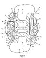
- FIG 2 illustrates the intervertebral implant when both pieces 30 and 32 are embedded in their housing 38.
- FIG 1 we will describe the components of self-locking fasteners block the links 16 and 18 in translation.
- link 18 whose first end 20 is connected to the wing 24, and a part 50 of which is arranged with respect to the groove 14 in which a spinous process, not shown, is likely to come in support. Link 18 then extends to the other wing of the groove 14 to join the self-locking fastening piece 30. As explained in the above description, link 18 is inserted in the fastener 30 prior to its embedding in dwelling 38.
- the self-locking fastener 30 presents a first main face 52 and a second main face 54 opposite to the first, the two opposite faces 52, 54 joining in the first end 56 and in the second end 58 of the fastener 30. It also has a central recess 60 forming a slot debouching in the first main face 52 and in the second face 54.
- the middle plane M of the recess 60 forms an acute angle alpha with the first part of the main face, for example 30 ° of to form a ridge 62.
- the second end 58 of the fastener 30 has two faces inclined with respect to the other, forming a ridge 64.
- the recess 60 opens at the level of the junction between the first main face and the second end 58, thus forming another edge 66.
- the free end 28 of the link 18 for example after being introduced into the lower interspinous space behind the interspinous ligament, is inserted outside the body into the central recess 60 forming a slot from the second main face 54 of the fastener 30.
- the fastener 30 is carried in view of the side wall of the shim 10 by sliding it along the link 18, and arranging it so that the first main face is with regard to the side wall and, that the link part 18 extending the lower interspinous space and the part of link 18 extending through the second free end 28 open into the open end 39 of the fastener 30.
- a link part 18 prolonging the lower interspinous space is applied against the first main face of the fastener 30, then bypasses the second end 58 and applies against a portion of the second face 54 before passing through the central recess 60 forming a slot, for then lead into the first main face 52 and lean against a part of the first main face 52 which joins the first end 56.
- link 18 is illustrated by a line so as not to overload the drawing, but the link 18 has a thickness such that the contact between the two portions 70 and 72 is made possible with the configuration of the fastener 30 and the hold 10.
- link 18 is stretched in the fastener 30 and over, no only the two portions 70 and 72 of link 18 are compressed together, but also the friction means formed by the edges 62 or 66, for example, are effective at blocking the link in translation in a direction opposite to F. In this way, link 18 is maintained immobile in translation relative to the hold 10 and holds the hold 10 on the spinous process.
Landscapes
- Health & Medical Sciences (AREA)
- Orthopedic Medicine & Surgery (AREA)
- Neurology (AREA)
- Life Sciences & Earth Sciences (AREA)
- Surgery (AREA)
- Engineering & Computer Science (AREA)
- Biomedical Technology (AREA)
- General Health & Medical Sciences (AREA)
- Veterinary Medicine (AREA)
- Heart & Thoracic Surgery (AREA)
- Public Health (AREA)
- Animal Behavior & Ethology (AREA)
- Molecular Biology (AREA)
- Medical Informatics (AREA)
- Nuclear Medicine, Radiotherapy & Molecular Imaging (AREA)
- Cardiology (AREA)
- Oral & Maxillofacial Surgery (AREA)
- Transplantation (AREA)
- Vascular Medicine (AREA)
- Prostheses (AREA)
- Materials For Medical Uses (AREA)
- Slide Fasteners, Snap Fasteners, And Hook Fasteners (AREA)
Description
- la Figure 1 est une vue schématique éclatée de profil montrant l'implant conforme à l'invention ; et,
- la Figure 2, est une vue schématique en coupe verticale de l'invention illustrée sur la Figure 1, l'implant étant monté.
Claims (10)
- Implant intervertébral comprenant une cale (10) dans laquelle sont ménagées deux gorges (12, 14) opposées l'une de l'autre que l'axe longitudinal (A) de ladite cale (10) traverse et qui sont susceptibles de recevoir les deux apophyses épineuses de deux vertèbres, ladite cale (10) présentant deux parois latérales et au moins un lien (16, 18) de fixation pour maintenir lesdites apophyses épineuses dans lesdites gorges (12, 14), la première extrémité (20) dudit lien (16, 18) étant susceptible d'être relié à ladite cale (10), ledit lien (16, 18) étant susceptible d'entourer au moins une apophyse épineuse et la seconde extrémité (28) dudit lien étant libre,
caractérisé en ce qu'il comprend au moins une pièce de fixation auto-bloquante amovible (30, 32) présentant des premiers moyens de liaison (34) et à travers laquelle ledit lien (16, 18) est susceptible de coulisser lorsqu'il est entraíné en translation selon une première direction (R, F), ladite pièce de fixation auto-bloquante (30, 32) étant susceptible de bloquer ledit lien (16, 18) en translation selon une seconde direction opposée à ladite première direction (R, F) ;
et en ce que au moins une des deux parois latérales (36) de ladite cale (10) comporte des deuxièmes moyens de liaison (38) aptes à coopérer avec lesdits premiers moyens de liaison (34) pour relier ladite pièce de fixation auto-bloquante amovible (30, 32) à la paroi latérale (36) de ladite cale (10), l'entraínement de ladite extrémité libre (28) dudit lien (16, 18) de façon à entraíner ledit lien (16, 18) en translation selon ladite première direction (R, F) produisant le serrage de ladite apophyse épineuse dans ladite gorge (12, 14) et le blocage dudit lien (16, 18) en translation selon ladite seconde direction par rapport à ladite cale (10). - Implant intervertébral selon la revendication 1, caractérisé en ce que ladite pièce de fixation auto-bloquante amovible (30, 32) présente une première face principale (52) opposée à une seconde face principale (54) qui sont reliées aux deux extrémités (56, 58) de ladite pièce de fixation auto-bloquante amovible (30, 32) et un évidement central (60) formant fente, débouchant dans lesdites faces principales (52, 54), que ledit lien (16, 18) traverse, de façon qu'une première portion (70) dudit lien (16, 18) comprise entre ladite première extrémité (20) et ledit évidement central (60) soit susceptible de comprimer une deuxième portion (72) dudit lien comprise entre ledit évidement central (60) et ladite deuxième extrémité libre (28) dudit lien contre une partie de ladite première face principale (52) rejoignant la première (56) desdites extrémités de ladite pièce de fixation auto-bloquante (30, 32) pour maintenir ledit lien (16, 18) en position fixe par rapport à ladite pièce de fixation auto-bloquante (30, 32).
- Implant intervertébral selon la revendication 2, caractérisé en ce que ladite pièce de fixation auto-bloquante amovible (30, 32) présente un évidement central formant fente (60) dont le plan moyen (M) forme un angle aigu (α) avec ladite première partie de ladite première face principale (52) de façon à former une arête (62) dans chacune des faces principales (52, 54) susceptible de former des premiers moyens de frottement pour ledit lien (16, 18).
- Implant intervertébral selon la revendication 2 ou 3, caractérisé en ce que la seconde (58) desdites extrémités de ladite pièce de fixation auto-bloquante amovible (30, 32) contre laquelle s'appuie ledit lien (16, 18), présente deux faces inclinées l'une par rapport à l'autre de façon à former une arête (64) susceptible de former des deuxièmes moyens de frottement pour ledit lien.
- Implant intervertébral selon l'une quelconque des revendications 1 à 4,
caractérisé en ce que lesdits deuxièmes moyens de liaison (38) comprennent un logement ménagé dans ladite paroi latérale (36) de ladite cale (10) dont les deux bords opposés (40, 42), sensiblement parallèles audit axe (A) de la cale, présentent des moyens (44) formant butée s'étendant sensiblement perpendiculairement à ladite paroi latérale (36) de ladite cale,
et en ce que lesdits premiers moyens de liaison (34) font saillie dans les bords latéraux de ladite pièce de fixation auto-bloquante amovible (30, 32) pour venir en appui contre lesdits moyens (44) formant butée de façon à bloquer ladite pièce de fixation auto-bloquante amovible (30, 32) en translation par rapport à ladite cale, dans une direction sensiblement parallèle audit axe longitudinal (A) correspondant à ladite seconde direction de blocage dudit lien en translation par rapport à ladite cale (10). - Implant intervertébral selon la revendication 5, caractérisé en ce que ledit logement présente une extrémité ouverte (39) située au regard de ladite première (56) desdites extrémités de la pièce de fixation auto-bloquante amovible (30, 32) à travers laquelle ledit lien (16, 18) est susceptible de coulisser.
- Implant intervertébral selon la revendication 5 ou 6,
caractérisé en ce que lesdits moyens (44) formant butée sont constitués par au moins deux évidements oblongs en regard pratiqués sensiblement perpendiculairement à ladite paroi latérale (36) de la cale dans les deux bords opposés (40, 42) dudit logement ;
et en ce que lesdits premiers moyens de liaison (34) forment des tétons faisant saillie dans les bords latéraux de ladite pièce de fixation auto-bloquante (30, 32), dans le prolongement l'un de l'autre, de façon à s'encastrer perpendiculairement à ladite paroi latérale (36) dans lesdits évidements oblongs (44). - Implant intervertébral selon la revendication 7, caractérisé en ce que lesdits évidements oblongs (44) présentent une portion étranglée (46) élastiquement déformable située entre une portion d'entrée et une portion de fond, susceptible de se déformer par enfoncement à force dudit téton (34) de façon que ledit téton (34) soit maintenu en position fixe dans ladite portion de fond.
- Implant intervertébral selon l'une quelconque des revendications 1 à 8, caractérisé en ce qu'il comprend deux liens (16, 18) susceptibles d'entourer respectivement une apophyse épineuse supérieure et une apophyse épineuse inférieure, et deux pièces de fixation auto-bloquante amovibles (30, 32) susceptibles d'être reliées aux deux parois latérales (36) de ladite cale (10).
- Implant intervertébral selon l'une quelconque des revendications 1 à 9, caractérisé en ce que ladite cale (10) et ladite pièce de fixation auto-bloquante amovible (30, 32) sont réalisés en matière plastique.
Applications Claiming Priority (3)
| Application Number | Priority Date | Filing Date | Title |
|---|---|---|---|
| FR0103362A FR2822051B1 (fr) | 2001-03-13 | 2001-03-13 | Implant intervertebral a fixation auto-bloquante |
| FR0103362 | 2001-03-13 | ||
| PCT/FR2002/000888 WO2002071960A1 (fr) | 2001-03-13 | 2002-03-13 | Implant intervertebral a fixation auto-bloquante |
Publications (2)
| Publication Number | Publication Date |
|---|---|
| EP1367954A1 EP1367954A1 (fr) | 2003-12-10 |
| EP1367954B1 true EP1367954B1 (fr) | 2005-01-05 |
Family
ID=8861029
Family Applications (1)
| Application Number | Title | Priority Date | Filing Date |
|---|---|---|---|
| EP02722342A Expired - Lifetime EP1367954B1 (fr) | 2001-03-13 | 2002-03-13 | Implant intervertebral a fixation auto-bloquante |
Country Status (13)
| Country | Link |
|---|---|
| US (1) | US7087083B2 (fr) |
| EP (1) | EP1367954B1 (fr) |
| JP (1) | JP4088529B2 (fr) |
| KR (1) | KR100859618B1 (fr) |
| AT (1) | ATE286368T1 (fr) |
| AU (1) | AU2002253232B2 (fr) |
| DE (1) | DE60202518T2 (fr) |
| ES (1) | ES2235030T3 (fr) |
| FR (1) | FR2822051B1 (fr) |
| TW (1) | TW590756B (fr) |
| UY (1) | UY27205A1 (fr) |
| WO (1) | WO2002071960A1 (fr) |
| ZA (1) | ZA200306967B (fr) |
Families Citing this family (296)
| Publication number | Priority date | Publication date | Assignee | Title |
|---|---|---|---|---|
| US7306628B2 (en) | 2002-10-29 | 2007-12-11 | St. Francis Medical Technologies | Interspinous process apparatus and method with a selectably expandable spacer |
| US20080039859A1 (en) * | 1997-01-02 | 2008-02-14 | Zucherman James F | Spine distraction implant and method |
| US20050245937A1 (en) * | 2004-04-28 | 2005-11-03 | St. Francis Medical Technologies, Inc. | System and method for insertion of an interspinous process implant that is rotatable in order to retain the implant relative to the spinous processes |
| US7201751B2 (en) * | 1997-01-02 | 2007-04-10 | St. Francis Medical Technologies, Inc. | Supplemental spine fixation device |
| US20080086212A1 (en) | 1997-01-02 | 2008-04-10 | St. Francis Medical Technologies, Inc. | Spine distraction implant |
| US20080071378A1 (en) * | 1997-01-02 | 2008-03-20 | Zucherman James F | Spine distraction implant and method |
| US8128661B2 (en) | 1997-01-02 | 2012-03-06 | Kyphon Sarl | Interspinous process distraction system and method with positionable wing and method |
| US20080027552A1 (en) * | 1997-01-02 | 2008-01-31 | Zucherman James F | Spine distraction implant and method |
| US7959652B2 (en) | 2005-04-18 | 2011-06-14 | Kyphon Sarl | Interspinous process implant having deployable wings and method of implantation |
| US6068630A (en) | 1997-01-02 | 2000-05-30 | St. Francis Medical Technologies, Inc. | Spine distraction implant |
| US8187303B2 (en) | 2004-04-22 | 2012-05-29 | Gmedelaware 2 Llc | Anti-rotation fixation element for spinal prostheses |
| US7674293B2 (en) | 2004-04-22 | 2010-03-09 | Facet Solutions, Inc. | Crossbar spinal prosthesis having a modular design and related implantation methods |
| ES2298675T3 (es) | 1999-10-22 | 2008-05-16 | Archus Orthopedics Inc. | Dispositivos de artroplastia facetaria. |
| US7691145B2 (en) | 1999-10-22 | 2010-04-06 | Facet Solutions, Inc. | Prostheses, systems and methods for replacement of natural facet joints with artificial facet joint surfaces |
| FR2812186B1 (fr) | 2000-07-25 | 2003-02-28 | Spine Next Sa | Piece de liaison souple pour la stabilisation du rachis |
| US20050080486A1 (en) | 2000-11-29 | 2005-04-14 | Fallin T. Wade | Facet joint replacement |
| US6579319B2 (en) * | 2000-11-29 | 2003-06-17 | Medicinelodge, Inc. | Facet joint replacement |
| US6565605B2 (en) | 2000-12-13 | 2003-05-20 | Medicinelodge, Inc. | Multiple facet joint replacement |
| US6419703B1 (en) | 2001-03-01 | 2002-07-16 | T. Wade Fallin | Prosthesis for the replacement of a posterior element of a vertebra |
| US7090698B2 (en) | 2001-03-02 | 2006-08-15 | Facet Solutions | Method and apparatus for spine joint replacement |
| FR2824261B1 (fr) | 2001-05-04 | 2004-05-28 | Ldr Medical | Prothese de disque intervertebral et procede et outils de mise en place |
| FR2828398B1 (fr) * | 2001-08-08 | 2003-09-19 | Jean Taylor | Ensemble de stabilisation de vertebres |
| FR2832917B1 (fr) * | 2001-11-30 | 2004-09-24 | Spine Next Sa | Implant intervertebral a cale elastiquement deformable |
| US6793678B2 (en) | 2002-06-27 | 2004-09-21 | Depuy Acromed, Inc. | Prosthetic intervertebral motion disc having dampening |
| FR2842724B1 (fr) | 2002-07-23 | 2005-05-27 | Spine Next Sa | Systeme de fixation vertebrale |
| FR2844179B1 (fr) | 2002-09-10 | 2004-12-03 | Jean Taylor | Ensemble de soutien vertebral posterieur |
| US7909853B2 (en) | 2004-09-23 | 2011-03-22 | Kyphon Sarl | Interspinous process implant including a binder and method of implantation |
| US20050075634A1 (en) * | 2002-10-29 | 2005-04-07 | Zucherman James F. | Interspinous process implant with radiolucent spacer and lead-in tissue expander |
| US8070778B2 (en) | 2003-05-22 | 2011-12-06 | Kyphon Sarl | Interspinous process implant with slide-in distraction piece and method of implantation |
| US7833246B2 (en) * | 2002-10-29 | 2010-11-16 | Kyphon SÀRL | Interspinous process and sacrum implant and method |
| US7931674B2 (en) | 2005-03-21 | 2011-04-26 | Kyphon Sarl | Interspinous process implant having deployable wing and method of implantation |
| US8221463B2 (en) * | 2002-10-29 | 2012-07-17 | Kyphon Sarl | Interspinous process implants and methods of use |
| US8048117B2 (en) | 2003-05-22 | 2011-11-01 | Kyphon Sarl | Interspinous process implant and method of implantation |
| US8147548B2 (en) | 2005-03-21 | 2012-04-03 | Kyphon Sarl | Interspinous process implant having a thread-shaped wing and method of implantation |
| US7549999B2 (en) | 2003-05-22 | 2009-06-23 | Kyphon Sarl | Interspinous process distraction implant and method of implantation |
| US20060064165A1 (en) * | 2004-09-23 | 2006-03-23 | St. Francis Medical Technologies, Inc. | Interspinous process implant including a binder and method of implantation |
| US7582088B2 (en) | 2003-02-07 | 2009-09-01 | Dsm Ip Assets B.V. | Bone fixing device |
| EP1444960A1 (fr) * | 2003-02-07 | 2004-08-11 | DSM IP Assets B.V. | Dispositif d'osteosynthese |
| US7335203B2 (en) | 2003-02-12 | 2008-02-26 | Kyphon Inc. | System and method for immobilizing adjacent spinous processes |
| WO2004084742A1 (fr) | 2003-03-24 | 2004-10-07 | Theken Surgical Llc | Dispositif de reglage d'implant vertebral |
| US7608104B2 (en) | 2003-05-14 | 2009-10-27 | Archus Orthopedics, Inc. | Prostheses, tools and methods for replacement of natural facet joints with artifical facet joint surfaces |
| US20040230304A1 (en) | 2003-05-14 | 2004-11-18 | Archus Orthopedics Inc. | Prostheses, tools and methods for replacement of natural facet joints with artifical facet joint surfaces |
| US7074238B2 (en) | 2003-07-08 | 2006-07-11 | Archus Orthopedics, Inc. | Prostheses, tools and methods for replacement of natural facet joints with artificial facet joint surfaces |
| FR2858929B1 (fr) * | 2003-08-21 | 2005-09-30 | Spine Next Sa | "implant intervertebral pour l'articulation lombo-sacree" |
| US8926700B2 (en) | 2003-12-10 | 2015-01-06 | Gmedelware 2 LLC | Spinal facet joint implant |
| US20050131406A1 (en) | 2003-12-15 | 2005-06-16 | Archus Orthopedics, Inc. | Polyaxial adjustment of facet joint prostheses |
| JP2007519456A (ja) * | 2004-01-30 | 2007-07-19 | ディーエスエム アイピー アセッツ ビー.ブイ. | 固定装置 |
| ES2547532T3 (es) | 2004-02-04 | 2015-10-07 | Ldr Medical | Prótesis de disco intervertebral |
| FR2865629B1 (fr) | 2004-02-04 | 2007-01-26 | Ldr Medical | Prothese de disque intervertebral |
| US20050177179A1 (en) * | 2004-02-10 | 2005-08-11 | Baynham Bret O. | Surgical cable system |
| US7993373B2 (en) | 2005-02-22 | 2011-08-09 | Hoy Robert W | Polyaxial orthopedic fastening apparatus |
| US8333789B2 (en) | 2007-01-10 | 2012-12-18 | Gmedelaware 2 Llc | Facet joint replacement |
| US8562649B2 (en) | 2004-02-17 | 2013-10-22 | Gmedelaware 2 Llc | System and method for multiple level facet joint arthroplasty and fusion |
| US8523904B2 (en) | 2004-03-09 | 2013-09-03 | The Board Of Trustees Of The Leland Stanford Junior University | Methods and systems for constraint of spinous processes with attachment |
| US7458981B2 (en) | 2004-03-09 | 2008-12-02 | The Board Of Trustees Of The Leland Stanford Junior University | Spinal implant and method for restricting spinal flexion |
| US7406775B2 (en) | 2004-04-22 | 2008-08-05 | Archus Orthopedics, Inc. | Implantable orthopedic device component selection instrument and methods |
| US7051451B2 (en) | 2004-04-22 | 2006-05-30 | Archus Orthopedics, Inc. | Facet joint prosthesis measurement and implant tools |
| US7544208B1 (en) | 2004-05-03 | 2009-06-09 | Theken Spine, Llc | Adjustable corpectomy apparatus |
| FR2870106B1 (fr) * | 2004-05-11 | 2007-07-27 | Spine Next Sa | Implant intervertebral |
| FR2870107B1 (fr) | 2004-05-11 | 2007-07-27 | Spine Next Sa | Dispositif autobloquant de fixation d'un implant intervertebral |
| FR2870109B1 (fr) * | 2004-05-17 | 2007-04-13 | Spine Next Sa | Cale intervertebrale pour vertebres cervicales |
| WO2005110258A1 (fr) * | 2004-05-17 | 2005-11-24 | Wooridul Spine Health Institute Co. | Insert vertebral |
| US7585316B2 (en) * | 2004-05-21 | 2009-09-08 | Warsaw Orthopedic, Inc. | Interspinous spacer |
| FR2870719B1 (fr) * | 2004-05-27 | 2007-09-21 | Spine Next Sa | Systeme d'arthroplastie rachidienne |
| US8764801B2 (en) | 2005-03-28 | 2014-07-01 | Gmedelaware 2 Llc | Facet joint implant crosslinking apparatus and method |
| US7588578B2 (en) | 2004-06-02 | 2009-09-15 | Facet Solutions, Inc | Surgical measurement systems and methods |
| US7758581B2 (en) | 2005-03-28 | 2010-07-20 | Facet Solutions, Inc. | Polyaxial reaming apparatus and method |
| US7854752B2 (en) | 2004-08-09 | 2010-12-21 | Theken Spine, Llc | System and method for dynamic skeletal stabilization |
| KR20070065329A (ko) | 2004-08-18 | 2007-06-22 | 아추스 오토페딕스, 인코포레이티드 | 인접 레벨 관절면 관절성형 장치, 척추 안정화 시스템, 및그 방법들 |
| US8012209B2 (en) | 2004-09-23 | 2011-09-06 | Kyphon Sarl | Interspinous process implant including a binder, binder aligner and method of implantation |
| US8613747B2 (en) | 2004-10-20 | 2013-12-24 | Vertiflex, Inc. | Spacer insertion instrument |
| US8277488B2 (en) | 2004-10-20 | 2012-10-02 | Vertiflex, Inc. | Interspinous spacer |
| US8012207B2 (en) | 2004-10-20 | 2011-09-06 | Vertiflex, Inc. | Systems and methods for posterior dynamic stabilization of the spine |
| US9119680B2 (en) | 2004-10-20 | 2015-09-01 | Vertiflex, Inc. | Interspinous spacer |
| US8152837B2 (en) | 2004-10-20 | 2012-04-10 | The Board Of Trustees Of The Leland Stanford Junior University | Systems and methods for posterior dynamic stabilization of the spine |
| US7763074B2 (en) | 2004-10-20 | 2010-07-27 | The Board Of Trustees Of The Leland Stanford Junior University | Systems and methods for posterior dynamic stabilization of the spine |
| US8123782B2 (en) | 2004-10-20 | 2012-02-28 | Vertiflex, Inc. | Interspinous spacer |
| US8167944B2 (en) | 2004-10-20 | 2012-05-01 | The Board Of Trustees Of The Leland Stanford Junior University | Systems and methods for posterior dynamic stabilization of the spine |
| US8409282B2 (en) | 2004-10-20 | 2013-04-02 | Vertiflex, Inc. | Systems and methods for posterior dynamic stabilization of the spine |
| US9161783B2 (en) | 2004-10-20 | 2015-10-20 | Vertiflex, Inc. | Interspinous spacer |
| US8128662B2 (en) | 2004-10-20 | 2012-03-06 | Vertiflex, Inc. | Minimally invasive tooling for delivery of interspinous spacer |
| US8425559B2 (en) | 2004-10-20 | 2013-04-23 | Vertiflex, Inc. | Systems and methods for posterior dynamic stabilization of the spine |
| US9023084B2 (en) | 2004-10-20 | 2015-05-05 | The Board Of Trustees Of The Leland Stanford Junior University | Systems and methods for stabilizing the motion or adjusting the position of the spine |
| US8317864B2 (en) | 2004-10-20 | 2012-11-27 | The Board Of Trustees Of The Leland Stanford Junior University | Systems and methods for posterior dynamic stabilization of the spine |
| US8123807B2 (en) | 2004-10-20 | 2012-02-28 | Vertiflex, Inc. | Systems and methods for posterior dynamic stabilization of the spine |
| US8945183B2 (en) | 2004-10-20 | 2015-02-03 | Vertiflex, Inc. | Interspinous process spacer instrument system with deployment indicator |
| US8273108B2 (en) | 2004-10-20 | 2012-09-25 | Vertiflex, Inc. | Interspinous spacer |
| US9055981B2 (en) | 2004-10-25 | 2015-06-16 | Lanx, Inc. | Spinal implants and methods |
| US8241330B2 (en) | 2007-01-11 | 2012-08-14 | Lanx, Inc. | Spinous process implants and associated methods |
| EP1807012B1 (fr) * | 2004-10-25 | 2016-07-06 | Lanx, LLC | Dispositifs de separation interspinale |
| CA2585135A1 (fr) | 2004-10-25 | 2006-05-26 | Archus Orthopedics, Inc. | Prothese vertebrale de conception modulaire |
| ATE524121T1 (de) | 2004-11-24 | 2011-09-15 | Abdou Samy | Vorrichtungen zur platzierung eines orthopädischen intervertebralen implantats |
| WO2009086010A2 (fr) | 2004-12-06 | 2009-07-09 | Vertiflex, Inc. | Instrument d'insertion d'un écarteur |
| FR2879436B1 (fr) | 2004-12-22 | 2007-03-09 | Ldr Medical | Prothese de disque intervertebral |
| US8092459B2 (en) * | 2005-02-17 | 2012-01-10 | Kyphon Sarl | Percutaneous spinal implants and methods |
| US8057513B2 (en) | 2005-02-17 | 2011-11-15 | Kyphon Sarl | Percutaneous spinal implants and methods |
| US20070276372A1 (en) * | 2005-02-17 | 2007-11-29 | Malandain Hugues F | Percutaneous Spinal Implants and Methods |
| US7993342B2 (en) | 2005-02-17 | 2011-08-09 | Kyphon Sarl | Percutaneous spinal implants and methods |
| US8096994B2 (en) | 2005-02-17 | 2012-01-17 | Kyphon Sarl | Percutaneous spinal implants and methods |
| US8097018B2 (en) | 2005-02-17 | 2012-01-17 | Kyphon Sarl | Percutaneous spinal implants and methods |
| US7998174B2 (en) | 2005-02-17 | 2011-08-16 | Kyphon Sarl | Percutaneous spinal implants and methods |
| US8029567B2 (en) | 2005-02-17 | 2011-10-04 | Kyphon Sarl | Percutaneous spinal implants and methods |
| US20070276493A1 (en) | 2005-02-17 | 2007-11-29 | Malandain Hugues F | Percutaneous spinal implants and methods |
| US8100943B2 (en) | 2005-02-17 | 2012-01-24 | Kyphon Sarl | Percutaneous spinal implants and methods |
| US7988709B2 (en) | 2005-02-17 | 2011-08-02 | Kyphon Sarl | Percutaneous spinal implants and methods |
| US8029549B2 (en) | 2005-02-17 | 2011-10-04 | Kyphon Sarl | Percutaneous spinal implants and methods |
| US7998208B2 (en) * | 2005-02-17 | 2011-08-16 | Kyphon Sarl | Percutaneous spinal implants and methods |
| US8157841B2 (en) | 2005-02-17 | 2012-04-17 | Kyphon Sarl | Percutaneous spinal implants and methods |
| US8007521B2 (en) | 2005-02-17 | 2011-08-30 | Kyphon Sarl | Percutaneous spinal implants and methods |
| US7927354B2 (en) | 2005-02-17 | 2011-04-19 | Kyphon Sarl | Percutaneous spinal implants and methods |
| US8096995B2 (en) | 2005-02-17 | 2012-01-17 | Kyphon Sarl | Percutaneous spinal implants and methods |
| US20070276373A1 (en) * | 2005-02-17 | 2007-11-29 | Malandain Hugues F | Percutaneous Spinal Implants and Methods |
| US8038698B2 (en) * | 2005-02-17 | 2011-10-18 | Kphon Sarl | Percutaneous spinal implants and methods |
| US8034080B2 (en) | 2005-02-17 | 2011-10-11 | Kyphon Sarl | Percutaneous spinal implants and methods |
| US7361196B2 (en) * | 2005-02-22 | 2008-04-22 | Stryker Spine | Apparatus and method for dynamic vertebral stabilization |
| JP2006253316A (ja) * | 2005-03-09 | 2006-09-21 | Sony Corp | 固体撮像装置 |
| US7722647B1 (en) | 2005-03-14 | 2010-05-25 | Facet Solutions, Inc. | Apparatus and method for posterior vertebral stabilization |
| US8496686B2 (en) | 2005-03-22 | 2013-07-30 | Gmedelaware 2 Llc | Minimally invasive spine restoration systems, devices, methods and kits |
| US8066742B2 (en) | 2005-03-31 | 2011-11-29 | Warsaw Orthopedic, Inc. | Intervertebral prosthetic device for spinal stabilization and method of implanting same |
| US20060241757A1 (en) * | 2005-03-31 | 2006-10-26 | Sdgi Holdings, Inc. | Intervertebral prosthetic device for spinal stabilization and method of manufacturing same |
| US7862590B2 (en) | 2005-04-08 | 2011-01-04 | Warsaw Orthopedic, Inc. | Interspinous process spacer |
| FR2884136B1 (fr) * | 2005-04-08 | 2008-02-22 | Spinevision Sa | Implant chirurgical intervertebral formant rotule |
| US8034079B2 (en) | 2005-04-12 | 2011-10-11 | Warsaw Orthopedic, Inc. | Implants and methods for posterior dynamic stabilization of a spinal motion segment |
| US7780709B2 (en) * | 2005-04-12 | 2010-08-24 | Warsaw Orthopedic, Inc. | Implants and methods for inter-transverse process dynamic stabilization of a spinal motion segment |
| US7789898B2 (en) * | 2005-04-15 | 2010-09-07 | Warsaw Orthopedic, Inc. | Transverse process/laminar spacer |
| US7727233B2 (en) * | 2005-04-29 | 2010-06-01 | Warsaw Orthopedic, Inc. | Spinous process stabilization devices and methods |
| US7951199B2 (en) * | 2005-06-15 | 2011-05-31 | Miller Jimmy D | Lateral expandable interbody fusion cage |
| JP2008543449A (ja) * | 2005-06-17 | 2008-12-04 | アボット・ラボラトリーズ | 変性脊椎疾患の改良型治療方法 |
| US20070005064A1 (en) * | 2005-06-27 | 2007-01-04 | Sdgi Holdings | Intervertebral prosthetic device for spinal stabilization and method of implanting same |
| FR2887434B1 (fr) | 2005-06-28 | 2008-03-28 | Jean Taylor | Materiel de traitement chirurgical de deux vertebres |
| FR2887762B1 (fr) | 2005-06-29 | 2007-10-12 | Ldr Medical Soc Par Actions Si | Instrumentation d'insertion de prothese de disque intervertebral entre des vertebres |
| FR2889937B1 (fr) * | 2005-08-26 | 2007-11-09 | Abbott Spine Sa | Implant intervertebral pour l'articulation lombo-sacree |
| PL377136A1 (pl) | 2005-09-19 | 2007-04-02 | Lfc Spółka Z Ograniczoną Odpowiedzialnością | Dystansowy implant międzywyrostkowy |
| FR2890850B1 (fr) | 2005-09-20 | 2009-04-17 | Abbott Spine Sa | Systeme de fixation vertebrale |
| FR2890851B1 (fr) | 2005-09-21 | 2008-06-20 | Abbott Spine Sa | Ancillaire de mise en tension d'un lien souple. |
| US20080183209A1 (en) * | 2005-09-23 | 2008-07-31 | Spinal Kinetics, Inc. | Spinal Stabilization Device |
| FR2891135B1 (fr) | 2005-09-23 | 2008-09-12 | Ldr Medical Sarl | Prothese de disque intervertebral |
| US8267970B2 (en) * | 2005-10-25 | 2012-09-18 | Depuy Spine, Inc. | Laminar hook spring |
| US8357181B2 (en) | 2005-10-27 | 2013-01-22 | Warsaw Orthopedic, Inc. | Intervertebral prosthetic device for spinal stabilization and method of implanting same |
| US8109973B2 (en) | 2005-10-31 | 2012-02-07 | Stryker Spine | Method for dynamic vertebral stabilization |
| US7862591B2 (en) * | 2005-11-10 | 2011-01-04 | Warsaw Orthopedic, Inc. | Intervertebral prosthetic device for spinal stabilization and method of implanting same |
| FR2893838B1 (fr) | 2005-11-30 | 2008-08-08 | Ldr Medical Soc Par Actions Si | Prothese de disque intervertebral et instrumentation d'insertion de la prothese entre les vertebres |
| WO2007075843A2 (fr) * | 2005-12-19 | 2007-07-05 | Abdou M S | Dispositifs et procédés de mise en place d'un dispositif orthopédique intervertébral |
| WO2007126428A2 (fr) | 2005-12-20 | 2007-11-08 | Archus Orthopedics, Inc. | Procédé et système de révision d'une arthroplastie |
| US20070173823A1 (en) | 2006-01-18 | 2007-07-26 | Sdgi Holdings, Inc. | Intervertebral prosthetic device for spinal stabilization and method of implanting same |
| US8083795B2 (en) | 2006-01-18 | 2011-12-27 | Warsaw Orthopedic, Inc. | Intervertebral prosthetic device for spinal stabilization and method of manufacturing same |
| US7682376B2 (en) | 2006-01-27 | 2010-03-23 | Warsaw Orthopedic, Inc. | Interspinous devices and methods of use |
| US7837711B2 (en) | 2006-01-27 | 2010-11-23 | Warsaw Orthopedic, Inc. | Artificial spinous process for the sacrum and methods of use |
| US7691130B2 (en) | 2006-01-27 | 2010-04-06 | Warsaw Orthopedic, Inc. | Spinal implants including a sensor and methods of use |
| US20070233068A1 (en) * | 2006-02-22 | 2007-10-04 | Sdgi Holdings, Inc. | Intervertebral prosthetic assembly for spinal stabilization and method of implanting same |
| FR2897771B1 (fr) | 2006-02-28 | 2008-06-06 | Abbott Spine Sa | Implant intervertebral |
| US8262698B2 (en) | 2006-03-16 | 2012-09-11 | Warsaw Orthopedic, Inc. | Expandable device for insertion between anatomical structures and a procedure utilizing same |
| US7985246B2 (en) * | 2006-03-31 | 2011-07-26 | Warsaw Orthopedic, Inc. | Methods and instruments for delivering interspinous process spacers |
| FR2899788B1 (fr) * | 2006-04-13 | 2008-07-04 | Jean Taylor | Materiel de traitement de vertebres, comprenant un implant interepineux |
| US8118844B2 (en) | 2006-04-24 | 2012-02-21 | Warsaw Orthopedic, Inc. | Expandable device for insertion between anatomical structures and a procedure utilizing same |
| US7846185B2 (en) | 2006-04-28 | 2010-12-07 | Warsaw Orthopedic, Inc. | Expandable interspinous process implant and method of installing same |
| US8252031B2 (en) | 2006-04-28 | 2012-08-28 | Warsaw Orthopedic, Inc. | Molding device for an expandable interspinous process implant |
| US8048118B2 (en) | 2006-04-28 | 2011-11-01 | Warsaw Orthopedic, Inc. | Adjustable interspinous process brace |
| US20070270823A1 (en) | 2006-04-28 | 2007-11-22 | Sdgi Holdings, Inc. | Multi-chamber expandable interspinous process brace |
| US8105357B2 (en) | 2006-04-28 | 2012-01-31 | Warsaw Orthopedic, Inc. | Interspinous process brace |
| US8348978B2 (en) * | 2006-04-28 | 2013-01-08 | Warsaw Orthopedic, Inc. | Interosteotic implant |
| US8062337B2 (en) | 2006-05-04 | 2011-11-22 | Warsaw Orthopedic, Inc. | Expandable device for insertion between anatomical structures and a procedure utilizing same |
| US8147517B2 (en) | 2006-05-23 | 2012-04-03 | Warsaw Orthopedic, Inc. | Systems and methods for adjusting properties of a spinal implant |
| US20070276496A1 (en) | 2006-05-23 | 2007-11-29 | Sdgi Holdings, Inc. | Surgical spacer with shape control |
| US8048119B2 (en) | 2006-07-20 | 2011-11-01 | Warsaw Orthopedic, Inc. | Apparatus for insertion between anatomical structures and a procedure utilizing same |
| WO2008019397A2 (fr) | 2006-08-11 | 2008-02-14 | Archus Orthopedics, Inc. | Connexion polyaxiale de rondelle inclinée pour une prothèse de colonne vertébrale dynamique |
| US20080086115A1 (en) * | 2006-09-07 | 2008-04-10 | Warsaw Orthopedic, Inc. | Intercostal spacer device and method for use in correcting a spinal deformity |
| EP2047813A1 (fr) | 2007-10-11 | 2009-04-15 | Abbott Spine | Système de fixation d'os et procédé d'utilisation |
| US20080082172A1 (en) * | 2006-09-29 | 2008-04-03 | Jackson Roger P | Interspinous process spacer |
| US8066750B2 (en) | 2006-10-06 | 2011-11-29 | Warsaw Orthopedic, Inc | Port structures for non-rigid bone plates |
| US8845726B2 (en) | 2006-10-18 | 2014-09-30 | Vertiflex, Inc. | Dilator |
| ES2400535T3 (es) | 2006-10-19 | 2013-04-10 | Simpirica Spine, Inc. | Estructuras para restringir apófisis espinosas con un único conector |
| US8162982B2 (en) * | 2006-10-19 | 2012-04-24 | Simpirica Spine, Inc. | Methods and systems for constraint of multiple spine segments |
| US8187307B2 (en) | 2006-10-19 | 2012-05-29 | Simpirica Spine, Inc. | Structures and methods for constraining spinal processes with single connector |
| US8029541B2 (en) | 2006-10-19 | 2011-10-04 | Simpirica Spine, Inc. | Methods and systems for laterally stabilized constraint of spinous processes |
| US20080262549A1 (en) * | 2006-10-19 | 2008-10-23 | Simpirica Spine, Inc. | Methods and systems for deploying spinous process constraints |
| US8097019B2 (en) | 2006-10-24 | 2012-01-17 | Kyphon Sarl | Systems and methods for in situ assembly of an interspinous process distraction implant |
| US20080177298A1 (en) * | 2006-10-24 | 2008-07-24 | St. Francis Medical Technologies, Inc. | Tensioner Tool and Method for Implanting an Interspinous Process Implant Including a Binder |
| FR2908035B1 (fr) | 2006-11-08 | 2009-05-01 | Jean Taylor | Implant interepineux |
| US7879104B2 (en) | 2006-11-15 | 2011-02-01 | Warsaw Orthopedic, Inc. | Spinal implant system |
| US20080114357A1 (en) * | 2006-11-15 | 2008-05-15 | Warsaw Orthopedic, Inc. | Inter-transverse process spacer device and method for use in correcting a spinal deformity |
| US8105382B2 (en) | 2006-12-07 | 2012-01-31 | Interventional Spine, Inc. | Intervertebral implant |
| DE102006059395A1 (de) * | 2006-12-08 | 2008-06-19 | Aesculap Ag & Co. Kg | Implantat und Implantatsystem |
| US7955392B2 (en) | 2006-12-14 | 2011-06-07 | Warsaw Orthopedic, Inc. | Interspinous process devices and methods |
| AU2008204784A1 (en) | 2007-01-10 | 2008-07-17 | Facet Solutions, Inc. | Taper-locking fixation system |
| US9265532B2 (en) | 2007-01-11 | 2016-02-23 | Lanx, Inc. | Interspinous implants and methods |
| US8465546B2 (en) | 2007-02-16 | 2013-06-18 | Ldr Medical | Intervertebral disc prosthesis insertion assemblies |
| CA2684461C (fr) | 2007-04-16 | 2015-06-30 | Vertiflex Inc. | Espaceur interspinal |
| US7799058B2 (en) * | 2007-04-19 | 2010-09-21 | Zimmer Gmbh | Interspinous spacer |
| US8840646B2 (en) | 2007-05-10 | 2014-09-23 | Warsaw Orthopedic, Inc. | Spinous process implants and methods |
| US20080281361A1 (en) * | 2007-05-10 | 2008-11-13 | Shannon Marlece Vittur | Posterior stabilization and spinous process systems and methods |
| US20080294199A1 (en) * | 2007-05-25 | 2008-11-27 | Andrew Kohm | Spinous process implants and methods of using the same |
| US8070779B2 (en) * | 2007-06-04 | 2011-12-06 | K2M, Inc. | Percutaneous interspinous process device and method |
| FR2916956B1 (fr) | 2007-06-08 | 2012-12-14 | Ldr Medical | Cage intersomatique,prothese intervertebrale,dispositif d'ancrage et instrumentation d'implantation |
| EP2182864B1 (fr) * | 2007-06-22 | 2016-06-08 | Empirical Spine, Inc. | Dispositifs pour restreindre de façon contrôlée la flexion de segments rachidiens |
| US20100036424A1 (en) | 2007-06-22 | 2010-02-11 | Simpirica Spine, Inc. | Methods and systems for increasing the bending stiffness and constraining the spreading of a spinal segment |
| US20110172708A1 (en) * | 2007-06-22 | 2011-07-14 | Simpirica Spine, Inc. | Methods and systems for increasing the bending stiffness of a spinal segment with elongation limit |
| US8900307B2 (en) | 2007-06-26 | 2014-12-02 | DePuy Synthes Products, LLC | Highly lordosed fusion cage |
| US8348976B2 (en) * | 2007-08-27 | 2013-01-08 | Kyphon Sarl | Spinous-process implants and methods of using the same |
| FR2921248A1 (fr) * | 2007-09-25 | 2009-03-27 | Abbott Spine Sa | Dispositif de serrage de deux portions d'une tresse et implant intervertebral comprenant une cale, une tresse et un tel dispositif de serrage |
| US8128635B2 (en) | 2007-10-23 | 2012-03-06 | Zimmer Spine S.A.S. | Bone fixation tensioning tool and method |
| ATE536824T1 (de) | 2007-10-23 | 2011-12-15 | Zimmer Spine | Befestigungsvorrichtungen und stabilisierungssysteme mit diesen befestigungsvorrichtungen |
| US20090118833A1 (en) * | 2007-11-05 | 2009-05-07 | Zimmer Spine, Inc. | In-situ curable interspinous process spacer |
| AU2009206098B2 (en) | 2008-01-15 | 2014-10-30 | Vertiflex, Inc. | Interspinous spacer |
| EP2471493A1 (fr) | 2008-01-17 | 2012-07-04 | Synthes GmbH | Implant intervertébral extensible et son procédé de fabrication associé |
| US8105358B2 (en) | 2008-02-04 | 2012-01-31 | Kyphon Sarl | Medical implants and methods |
| US8252029B2 (en) * | 2008-02-21 | 2012-08-28 | Zimmer Gmbh | Expandable interspinous process spacer with lateral support and method for implantation |
| US8114136B2 (en) | 2008-03-18 | 2012-02-14 | Warsaw Orthopedic, Inc. | Implants and methods for inter-spinous process dynamic stabilization of a spinal motion segment |
| CN102036623A (zh) | 2008-04-05 | 2011-04-27 | 斯恩蒂斯有限公司 | 可膨胀的椎间植入体 |
| ATE515239T1 (de) | 2008-04-24 | 2011-07-15 | Zimmer Spine | System zur stabilisierung von mindestens einem abschnitt der wirbelsäule |
| CN102036614B (zh) | 2008-05-20 | 2013-03-27 | 捷迈脊柱公司 | 用于稳固至少三个椎骨的系统 |
| EP2326267B1 (fr) * | 2008-06-06 | 2018-04-25 | Empirical Spine, Inc. | Appareil pour verrouillage d'un ruban implantable |
| WO2009149407A1 (fr) | 2008-06-06 | 2009-12-10 | Simpirica Spine, Inc. | Procédés et appareil de blocage d'une sangle |
| EP2296566A4 (fr) | 2008-06-06 | 2013-01-02 | Simpirica Spine Inc | Méthodes et appareil de mise en place d'éléments de contrainte de l'apophyse épineuse |
| US20100012068A1 (en) * | 2008-07-03 | 2010-01-21 | International Engine Intellectual Property Company , Llc | Prioritizing Use Of Engine Cold Start Aids To mitigate Effect Of Weakened Battery Bank |
| ES2523801T3 (es) | 2008-09-03 | 2014-12-01 | Simpirica Spine, Inc. | Aparato para acoplar una prótesis a un segmento de columna vertebral |
| US8114131B2 (en) | 2008-11-05 | 2012-02-14 | Kyphon Sarl | Extension limiting devices and methods of use for the spine |
| DE102009004730B4 (de) * | 2009-01-15 | 2017-02-02 | Aesculap Ag | Zwischenwirbelimplantat und Handhabungsinstrument für dieses Zwischenwirbelimplantat |
| US8114135B2 (en) | 2009-01-16 | 2012-02-14 | Kyphon Sarl | Adjustable surgical cables and methods for treating spinal stenosis |
| EP2395931A4 (fr) | 2009-02-02 | 2013-10-30 | Simpirica Spine Inc | Ancrage par attache au sacrum et ses procédés d'utilisation |
| JP2012520131A (ja) | 2009-03-10 | 2012-09-06 | シンピライカ スパイン, インコーポレイテッド | 外科用テザー装置および使用方法 |
| WO2010104975A1 (fr) | 2009-03-10 | 2010-09-16 | Simpirica Spine, Inc. | Dispositif d'attache chirurgicale et procédés d'utilisation |
| JP5681122B2 (ja) | 2009-03-10 | 2015-03-04 | シンピライカ スパイン, インコーポレイテッド | 外科用テザー装置および使用方法 |
| US9526620B2 (en) | 2009-03-30 | 2016-12-27 | DePuy Synthes Products, Inc. | Zero profile spinal fusion cage |
| WO2010114853A1 (fr) | 2009-03-30 | 2010-10-07 | Simpirica Spine, Inc. | Procédés et appareils destinés à améliorer la capacité de charge de cisaillement d'un segment spinal |
| KR20120013327A (ko) | 2009-03-31 | 2012-02-14 | 란스, 아이엔씨. | 극돌기 임플란트 및 이와 연관된 방법 |
| US8372117B2 (en) | 2009-06-05 | 2013-02-12 | Kyphon Sarl | Multi-level interspinous implants and methods of use |
| US8157842B2 (en) | 2009-06-12 | 2012-04-17 | Kyphon Sarl | Interspinous implant and methods of use |
| US20110040332A1 (en) * | 2009-08-11 | 2011-02-17 | Interventional Spine, Inc. | Spinous process spacer and implantation procedure |
| US8771317B2 (en) | 2009-10-28 | 2014-07-08 | Warsaw Orthopedic, Inc. | Interspinous process implant and method of implantation |
| US8795335B1 (en) | 2009-11-06 | 2014-08-05 | Samy Abdou | Spinal fixation devices and methods of use |
| US8764806B2 (en) | 2009-12-07 | 2014-07-01 | Samy Abdou | Devices and methods for minimally invasive spinal stabilization and instrumentation |
| US9393129B2 (en) | 2009-12-10 | 2016-07-19 | DePuy Synthes Products, Inc. | Bellows-like expandable interbody fusion cage |
| US8740948B2 (en) | 2009-12-15 | 2014-06-03 | Vertiflex, Inc. | Spinal spacer for cervical and other vertebra, and associated systems and methods |
| GB0922614D0 (en) | 2009-12-23 | 2010-02-10 | Butterfield Forbes | Device |
| US8114132B2 (en) | 2010-01-13 | 2012-02-14 | Kyphon Sarl | Dynamic interspinous process device |
| US8317831B2 (en) | 2010-01-13 | 2012-11-27 | Kyphon Sarl | Interspinous process spacer diagnostic balloon catheter and methods of use |
| US8262697B2 (en) | 2010-01-14 | 2012-09-11 | X-Spine Systems, Inc. | Modular interspinous fixation system and method |
| EP2351534B1 (fr) * | 2010-02-01 | 2012-08-22 | Zimmer Spine | Dispositif intervertébral |
| US8147526B2 (en) | 2010-02-26 | 2012-04-03 | Kyphon Sarl | Interspinous process spacer diagnostic parallel balloon catheter and methods of use |
| US8979860B2 (en) | 2010-06-24 | 2015-03-17 | DePuy Synthes Products. LLC | Enhanced cage insertion device |
| US9282979B2 (en) | 2010-06-24 | 2016-03-15 | DePuy Synthes Products, Inc. | Instruments and methods for non-parallel disc space preparation |
| AU2011271465B2 (en) | 2010-06-29 | 2015-03-19 | Synthes Gmbh | Distractible intervertebral implant |
| US8814908B2 (en) | 2010-07-26 | 2014-08-26 | Warsaw Orthopedic, Inc. | Injectable flexible interspinous process device system |
| EP2624774A4 (fr) | 2010-10-06 | 2014-01-15 | Simpirica Spine Inc | Dispositif et accessoires pour limiter la flexion |
| US9402732B2 (en) | 2010-10-11 | 2016-08-02 | DePuy Synthes Products, Inc. | Expandable interspinous process spacer implant |
| US8496689B2 (en) | 2011-02-23 | 2013-07-30 | Farzad Massoudi | Spinal implant device with fusion cage and fixation plates and method of implanting |
| US8562650B2 (en) | 2011-03-01 | 2013-10-22 | Warsaw Orthopedic, Inc. | Percutaneous spinous process fusion plate assembly and method |
| US8425560B2 (en) | 2011-03-09 | 2013-04-23 | Farzad Massoudi | Spinal implant device with fixation plates and lag screws and method of implanting |
| US8591548B2 (en) | 2011-03-31 | 2013-11-26 | Warsaw Orthopedic, Inc. | Spinous process fusion plate assembly |
| US8591549B2 (en) | 2011-04-08 | 2013-11-26 | Warsaw Orthopedic, Inc. | Variable durometer lumbar-sacral implant |
| US20120323276A1 (en) * | 2011-06-17 | 2012-12-20 | Bryan Okamoto | Expandable interspinous device |
| US9149306B2 (en) | 2011-06-21 | 2015-10-06 | Seaspine, Inc. | Spinous process device |
| US8845728B1 (en) | 2011-09-23 | 2014-09-30 | Samy Abdou | Spinal fixation devices and methods of use |
| US11812923B2 (en) | 2011-10-07 | 2023-11-14 | Alan Villavicencio | Spinal fixation device |
| KR101121667B1 (ko) * | 2012-01-17 | 2012-03-09 | 김창국 | 척추 극돌기 고정장치 |
| US20130226240A1 (en) | 2012-02-22 | 2013-08-29 | Samy Abdou | Spinous process fixation devices and methods of use |
| WO2014018098A1 (fr) | 2012-07-26 | 2014-01-30 | DePuy Synthes Products, LLC | Implant expansible |
| US9198767B2 (en) | 2012-08-28 | 2015-12-01 | Samy Abdou | Devices and methods for spinal stabilization and instrumentation |
| US20140067069A1 (en) | 2012-08-30 | 2014-03-06 | Interventional Spine, Inc. | Artificial disc |
| US9320617B2 (en) | 2012-10-22 | 2016-04-26 | Cogent Spine, LLC | Devices and methods for spinal stabilization and instrumentation |
| US9717601B2 (en) | 2013-02-28 | 2017-08-01 | DePuy Synthes Products, Inc. | Expandable intervertebral implant, system, kit and method |
| US9522070B2 (en) | 2013-03-07 | 2016-12-20 | Interventional Spine, Inc. | Intervertebral implant |
| US9510872B2 (en) * | 2013-03-15 | 2016-12-06 | Jcbd, Llc | Spinal stabilization system |
| US9675303B2 (en) | 2013-03-15 | 2017-06-13 | Vertiflex, Inc. | Visualization systems, instruments and methods of using the same in spinal decompression procedures |
| EP2801328A1 (fr) | 2013-05-06 | 2014-11-12 | Zimmer Spine | Dispositif intervertébral |
| DE102013016899A1 (de) | 2013-10-11 | 2015-05-21 | Josef Jansen | Gelenkspacer |
| WO2015171814A1 (fr) | 2014-05-07 | 2015-11-12 | Vertiflex, Inc. | Systèmes de décompression du nerf spinal, systèmes de dilatation, et leurs procédés d'utilisation |
| CA2966659A1 (fr) | 2014-11-06 | 2016-05-12 | Spinal Elements, Inc. | Appareil et procede de traitement d'apophyses epineuses |
| US9987052B2 (en) | 2015-02-24 | 2018-06-05 | X-Spine Systems, Inc. | Modular interspinous fixation system with threaded component |
| US11426290B2 (en) | 2015-03-06 | 2022-08-30 | DePuy Synthes Products, Inc. | Expandable intervertebral implant, system, kit and method |
| US9913727B2 (en) | 2015-07-02 | 2018-03-13 | Medos International Sarl | Expandable implant |
| US10857003B1 (en) | 2015-10-14 | 2020-12-08 | Samy Abdou | Devices and methods for vertebral stabilization |
| WO2018002715A2 (fr) | 2016-06-28 | 2018-01-04 | Eit Emerging Implant Technologies Gmbh | Cages intervertébrales articulées à expansion et réglage angulaire |
| EP3474783B1 (fr) | 2016-06-28 | 2023-05-03 | Eit Emerging Implant Technologies GmbH | Cages intervertébrales à expansion et réglage angulaire |
| US10744000B1 (en) | 2016-10-25 | 2020-08-18 | Samy Abdou | Devices and methods for vertebral bone realignment |
| US10973648B1 (en) | 2016-10-25 | 2021-04-13 | Samy Abdou | Devices and methods for vertebral bone realignment |
| US10537436B2 (en) | 2016-11-01 | 2020-01-21 | DePuy Synthes Products, Inc. | Curved expandable cage |
| US10888433B2 (en) | 2016-12-14 | 2021-01-12 | DePuy Synthes Products, Inc. | Intervertebral implant inserter and related methods |
| US10398563B2 (en) | 2017-05-08 | 2019-09-03 | Medos International Sarl | Expandable cage |
| US11344424B2 (en) | 2017-06-14 | 2022-05-31 | Medos International Sarl | Expandable intervertebral implant and related methods |
| US10940016B2 (en) | 2017-07-05 | 2021-03-09 | Medos International Sarl | Expandable intervertebral fusion cage |
| US10456174B2 (en) | 2017-07-31 | 2019-10-29 | Medos International Sarl | Connectors for use in systems and methods for reducing the risk of proximal junctional kyphosis |
| US10463403B2 (en) | 2017-07-31 | 2019-11-05 | Medos International Sarl | Systems and methods for reducing the risk of proximal junctional kyphosis using a bone anchor or other attachment point |
| US11179248B2 (en) | 2018-10-02 | 2021-11-23 | Samy Abdou | Devices and methods for spinal implantation |
| US11446156B2 (en) | 2018-10-25 | 2022-09-20 | Medos International Sarl | Expandable intervertebral implant, inserter instrument, and related methods |
| US11426286B2 (en) | 2020-03-06 | 2022-08-30 | Eit Emerging Implant Technologies Gmbh | Expandable intervertebral implant |
| US11850160B2 (en) | 2021-03-26 | 2023-12-26 | Medos International Sarl | Expandable lordotic intervertebral fusion cage |
| US11752009B2 (en) | 2021-04-06 | 2023-09-12 | Medos International Sarl | Expandable intervertebral fusion cage |
| US12589006B2 (en) | 2021-10-08 | 2026-03-31 | Seaspine Orthopedics Corporation | Expandable vertebral implant and method |
| US12102542B2 (en) | 2022-02-15 | 2024-10-01 | Boston Scientific Neuromodulation Corporation | Interspinous spacer and methods and systems utilizing the interspinous spacer |
| US12090064B2 (en) | 2022-03-01 | 2024-09-17 | Medos International Sarl | Stabilization members for expandable intervertebral implants, and related systems and methods |
| CN115006115B (zh) * | 2022-06-20 | 2023-03-24 | 西安市第一医院 | 一种m形胶带的扯断装置 |
| US12433646B2 (en) | 2023-02-21 | 2025-10-07 | Boston Scientific Neuromodulation Corporation | Interspinous spacer with actuator locking arrangements and methods and systems |
| US12390340B2 (en) | 2023-03-15 | 2025-08-19 | Boston Scientific Neuromodulation Corporation | Interspinous spacer with a range of deployment positions and methods and systems |
| CN119385668B (zh) * | 2024-12-23 | 2025-06-10 | 江苏澍寰宇泽医疗科技有限公司 | 一种骨科支撑件 |
Family Cites Families (10)
| Publication number | Priority date | Publication date | Assignee | Title |
|---|---|---|---|---|
| US5356412A (en) * | 1992-10-09 | 1994-10-18 | United States Surgical Corporation | Sternum buckle with rotational engagement and method of closure |
| US5496318A (en) * | 1993-01-08 | 1996-03-05 | Advanced Spine Fixation Systems, Inc. | Interspinous segmental spine fixation device |
| FR2704745B1 (fr) * | 1993-05-07 | 1995-11-24 | Erpios | Dispositif de liaison des extrémités d'un ligament d'ostéosynthèse, notamment d'ostéosynthèse vertébrale. |
| FR2717675B1 (fr) * | 1994-03-24 | 1996-05-03 | Jean Taylor | Cale inter-épineuse. |
| FR2722088B1 (fr) * | 1994-07-08 | 1998-01-23 | Cahlik Marc Andre | Implant chirurgical de stabilisation de l'espace intervertebral |
| US6514256B2 (en) * | 1997-01-02 | 2003-02-04 | St. Francis Medical Technologies, Inc. | Spine distraction implant and method |
| FR2775183B1 (fr) * | 1998-02-20 | 2000-08-04 | Jean Taylor | Prothese inter-epineuse |
| DE29916884U1 (de) * | 1999-09-24 | 2000-11-02 | Waldemar Link GmbH & Co., 22339 Hamburg | Chirurgisches Cerclageband |
| CA2405023A1 (fr) * | 2000-10-24 | 2002-05-16 | The Spineology Group, Llc | Clip de hauban |
| FR2818530B1 (fr) * | 2000-12-22 | 2003-10-31 | Spine Next Sa | Implant intervertebral a cale deformable |
-
2001
- 2001-03-13 FR FR0103362A patent/FR2822051B1/fr not_active Expired - Fee Related
-
2002
- 2002-03-12 UY UY27205A patent/UY27205A1/es not_active Application Discontinuation
- 2002-03-13 AU AU2002253232A patent/AU2002253232B2/en not_active Ceased
- 2002-03-13 TW TW091104688A patent/TW590756B/zh not_active IP Right Cessation
- 2002-03-13 KR KR20037010300A patent/KR100859618B1/ko not_active Expired - Fee Related
- 2002-03-13 US US10/471,213 patent/US7087083B2/en not_active Expired - Fee Related
- 2002-03-13 AT AT02722342T patent/ATE286368T1/de not_active IP Right Cessation
- 2002-03-13 ES ES02722342T patent/ES2235030T3/es not_active Expired - Lifetime
- 2002-03-13 JP JP2002570921A patent/JP4088529B2/ja not_active Expired - Lifetime
- 2002-03-13 DE DE60202518T patent/DE60202518T2/de not_active Expired - Lifetime
- 2002-03-13 WO PCT/FR2002/000888 patent/WO2002071960A1/fr not_active Ceased
- 2002-03-13 EP EP02722342A patent/EP1367954B1/fr not_active Expired - Lifetime
-
2003
- 2003-09-05 ZA ZA200306967A patent/ZA200306967B/en unknown
Also Published As
| Publication number | Publication date |
|---|---|
| KR100859618B1 (ko) | 2008-09-23 |
| AU2002253232B2 (en) | 2006-06-08 |
| US7087083B2 (en) | 2006-08-08 |
| DE60202518T2 (de) | 2006-05-04 |
| KR20030081423A (ko) | 2003-10-17 |
| FR2822051B1 (fr) | 2004-02-27 |
| US20040117017A1 (en) | 2004-06-17 |
| FR2822051A1 (fr) | 2002-09-20 |
| ZA200306967B (en) | 2004-09-06 |
| TW590756B (en) | 2004-06-11 |
| ES2235030T3 (es) | 2005-07-01 |
| WO2002071960A1 (fr) | 2002-09-19 |
| JP2004535846A (ja) | 2004-12-02 |
| JP4088529B2 (ja) | 2008-05-21 |
| EP1367954A1 (fr) | 2003-12-10 |
| UY27205A1 (es) | 2002-04-26 |
| ATE286368T1 (de) | 2005-01-15 |
| DE60202518D1 (de) | 2005-02-10 |
Similar Documents
| Publication | Publication Date | Title |
|---|---|---|
| EP1367954B1 (fr) | Implant intervertebral a fixation auto-bloquante | |
| EP1448109B1 (fr) | Implant intervertebral a cale elastiquement deformable | |
| EP2521500A1 (fr) | Dispositif de fixation vertebrale | |
| WO2005120369A1 (fr) | Implant intervertebral | |
| CA2971001C (fr) | Dispositif de fixation d'une bande plate sur une partie osseuse | |
| FR2976033A1 (fr) | Dispositifs de fixation | |
| EP1220644A1 (fr) | Implant intervertebral | |
| CH694357A5 (fr) | Ensemble de fixation d'un tissu mou sur un os | |
| FR2761256A1 (fr) | Instrumentation d'osteosynthese rachidienne a connecteur de liaison entre une tige vertebrale et des organes d'ancrage osseux | |
| EP1924210A2 (fr) | Implant intervertebral pour l'articulation lombo-sacree | |
| FR2770767A1 (fr) | Implant pour vertebre | |
| CH618088A5 (fr) | ||
| FR2730156A1 (fr) | Cale inter epineuse | |
| FR2818530A1 (fr) | Implant intervertebral a cale deformable | |
| FR3000771A1 (fr) | Agrafe de fixation d'un panneau sur un support et assemblage obtenu | |
| EP1429672A1 (fr) | Dispositif de fixation vertebrale | |
| EP1746948A1 (fr) | Cale intervertebrale pour vertebres cervicales | |
| FR2685015A1 (fr) | Attache rapide pour la liaison d'au moins un element funiculaire par rapport a l'extremite d'un cordon. | |
| WO2009071772A1 (fr) | Dispositif perfectionne de jonction pour bandes transporteuses | |
| FR3008456A1 (fr) | Grappe d'attaches pour conduite tubulaire de plancher chauffant | |
| FR2784729A1 (fr) | Agrafe pour corde | |
| FR2948276A1 (fr) | Systeme d'osteosynthese, notamment pour osteosynthese rachidienne | |
| FR2956567A1 (fr) | Dispositif en forme de passant pour cordon souple | |
| WO2009133250A1 (fr) | Pince d'ancrage pour câble de télécommunications | |
| FR2597168A1 (fr) | Collier de serrage, notamment pour tube, cable ou autre conduit |
Legal Events
| Date | Code | Title | Description |
|---|---|---|---|
| PUAI | Public reference made under article 153(3) epc to a published international application that has entered the european phase |
Free format text: ORIGINAL CODE: 0009012 |
|
| 17P | Request for examination filed |
Effective date: 20030812 |
|
| AK | Designated contracting states |
Kind code of ref document: A1 Designated state(s): AT BE CH CY DE DK ES FI FR GB GR IE IT LI LU MC NL PT SE TR |
|
| AX | Request for extension of the european patent |
Extension state: AL LT LV MK RO SI |
|
| GRAP | Despatch of communication of intention to grant a patent |
Free format text: ORIGINAL CODE: EPIDOSNIGR1 |
|
| RTI1 | Title (correction) |
Free format text: INTERVERTEBRAL IMPLANT WITH SELF-LOCKING FIXATION |
|
| GRAS | Grant fee paid |
Free format text: ORIGINAL CODE: EPIDOSNIGR3 |
|
| GRAA | (expected) grant |
Free format text: ORIGINAL CODE: 0009210 |
|
| AK | Designated contracting states |
Kind code of ref document: B1 Designated state(s): AT BE CH CY DE DK ES FI FR GB GR IE IT LI LU MC NL PT SE TR |
|
| PG25 | Lapsed in a contracting state [announced via postgrant information from national office to epo] |
Ref country code: IE Free format text: LAPSE BECAUSE OF FAILURE TO SUBMIT A TRANSLATION OF THE DESCRIPTION OR TO PAY THE FEE WITHIN THE PRESCRIBED TIME-LIMIT Effective date: 20050105 Ref country code: TR Free format text: LAPSE BECAUSE OF FAILURE TO SUBMIT A TRANSLATION OF THE DESCRIPTION OR TO PAY THE FEE WITHIN THE PRESCRIBED TIME-LIMIT Effective date: 20050105 Ref country code: FI Free format text: LAPSE BECAUSE OF FAILURE TO SUBMIT A TRANSLATION OF THE DESCRIPTION OR TO PAY THE FEE WITHIN THE PRESCRIBED TIME-LIMIT Effective date: 20050105 Ref country code: NL Free format text: LAPSE BECAUSE OF FAILURE TO SUBMIT A TRANSLATION OF THE DESCRIPTION OR TO PAY THE FEE WITHIN THE PRESCRIBED TIME-LIMIT Effective date: 20050105 Ref country code: AT Free format text: LAPSE BECAUSE OF FAILURE TO SUBMIT A TRANSLATION OF THE DESCRIPTION OR TO PAY THE FEE WITHIN THE PRESCRIBED TIME-LIMIT Effective date: 20050105 |
|
| REG | Reference to a national code |
Ref country code: GB Ref legal event code: FG4D Free format text: NOT ENGLISH |
|
| REG | Reference to a national code |
Ref country code: CH Ref legal event code: EP |
|
| REG | Reference to a national code |
Ref country code: IE Ref legal event code: FG4D Free format text: FRENCH |
|
| REF | Corresponds to: |
Ref document number: 60202518 Country of ref document: DE Date of ref document: 20050210 Kind code of ref document: P |
|
| PG25 | Lapsed in a contracting state [announced via postgrant information from national office to epo] |
Ref country code: CY Free format text: LAPSE BECAUSE OF FAILURE TO SUBMIT A TRANSLATION OF THE DESCRIPTION OR TO PAY THE FEE WITHIN THE PRESCRIBED TIME-LIMIT Effective date: 20050313 Ref country code: LU Free format text: LAPSE BECAUSE OF NON-PAYMENT OF DUE FEES Effective date: 20050313 |
|
| PG25 | Lapsed in a contracting state [announced via postgrant information from national office to epo] |
Ref country code: MC Free format text: LAPSE BECAUSE OF NON-PAYMENT OF DUE FEES Effective date: 20050331 Ref country code: BE Free format text: LAPSE BECAUSE OF NON-PAYMENT OF DUE FEES Effective date: 20050331 |
|
| PG25 | Lapsed in a contracting state [announced via postgrant information from national office to epo] |
Ref country code: SE Free format text: LAPSE BECAUSE OF FAILURE TO SUBMIT A TRANSLATION OF THE DESCRIPTION OR TO PAY THE FEE WITHIN THE PRESCRIBED TIME-LIMIT Effective date: 20050405 Ref country code: GR Free format text: LAPSE BECAUSE OF FAILURE TO SUBMIT A TRANSLATION OF THE DESCRIPTION OR TO PAY THE FEE WITHIN THE PRESCRIBED TIME-LIMIT Effective date: 20050405 Ref country code: DK Free format text: LAPSE BECAUSE OF FAILURE TO SUBMIT A TRANSLATION OF THE DESCRIPTION OR TO PAY THE FEE WITHIN THE PRESCRIBED TIME-LIMIT Effective date: 20050405 |
|
| GBT | Gb: translation of ep patent filed (gb section 77(6)(a)/1977) |
Effective date: 20050415 |
|
| NLV1 | Nl: lapsed or annulled due to failure to fulfill the requirements of art. 29p and 29m of the patents act | ||
| REG | Reference to a national code |
Ref country code: ES Ref legal event code: FG2A Ref document number: 2235030 Country of ref document: ES Kind code of ref document: T3 |
|
| REG | Reference to a national code |
Ref country code: IE Ref legal event code: FD4D |
|
| BERE | Be: lapsed |
Owner name: SPINE NEXT Effective date: 20050331 |
|
| PLBE | No opposition filed within time limit |
Free format text: ORIGINAL CODE: 0009261 |
|
| STAA | Information on the status of an ep patent application or granted ep patent |
Free format text: STATUS: NO OPPOSITION FILED WITHIN TIME LIMIT |
|
| 26N | No opposition filed |
Effective date: 20051006 |
|
| REG | Reference to a national code |
Ref country code: GB Ref legal event code: FG4D Free format text: NOT ENGLISH |
|
| PG25 | Lapsed in a contracting state [announced via postgrant information from national office to epo] |
Ref country code: LI Free format text: LAPSE BECAUSE OF NON-PAYMENT OF DUE FEES Effective date: 20060331 Ref country code: CH Free format text: LAPSE BECAUSE OF NON-PAYMENT OF DUE FEES Effective date: 20060331 |
|
| REG | Reference to a national code |
Ref country code: FR Ref legal event code: CD |
|
| REG | Reference to a national code |
Ref country code: CH Ref legal event code: PL |
|
| BERE | Be: lapsed |
Owner name: SPINE NEXT Effective date: 20050331 |
|
| PG25 | Lapsed in a contracting state [announced via postgrant information from national office to epo] |
Ref country code: PT Free format text: LAPSE BECAUSE OF NON-PAYMENT OF DUE FEES Effective date: 20050605 |
|
| REG | Reference to a national code |
Ref country code: FR Ref legal event code: CD Ref country code: FR Ref legal event code: CJ |
|
| PGFP | Annual fee paid to national office [announced via postgrant information from national office to epo] |
Ref country code: IT Payment date: 20120316 Year of fee payment: 11 |
|
| PGFP | Annual fee paid to national office [announced via postgrant information from national office to epo] |
Ref country code: ES Payment date: 20120320 Year of fee payment: 11 |
|
| PG25 | Lapsed in a contracting state [announced via postgrant information from national office to epo] |
Ref country code: IT Free format text: LAPSE BECAUSE OF NON-PAYMENT OF DUE FEES Effective date: 20130313 |
|
| REG | Reference to a national code |
Ref country code: ES Ref legal event code: FD2A Effective date: 20140612 |
|
| PG25 | Lapsed in a contracting state [announced via postgrant information from national office to epo] |
Ref country code: ES Free format text: LAPSE BECAUSE OF NON-PAYMENT OF DUE FEES Effective date: 20130314 |
|
| REG | Reference to a national code |
Ref country code: FR Ref legal event code: PLFP Year of fee payment: 15 |
|
| REG | Reference to a national code |
Ref country code: FR Ref legal event code: PLFP Year of fee payment: 16 |
|
| PGFP | Annual fee paid to national office [announced via postgrant information from national office to epo] |
Ref country code: FR Payment date: 20170213 Year of fee payment: 16 Ref country code: DE Payment date: 20170307 Year of fee payment: 16 |
|
| PGFP | Annual fee paid to national office [announced via postgrant information from national office to epo] |
Ref country code: GB Payment date: 20170308 Year of fee payment: 16 |
|
| REG | Reference to a national code |
Ref country code: DE Ref legal event code: R119 Ref document number: 60202518 Country of ref document: DE |
|
| GBPC | Gb: european patent ceased through non-payment of renewal fee |
Effective date: 20180313 |
|
| PG25 | Lapsed in a contracting state [announced via postgrant information from national office to epo] |
Ref country code: DE Free format text: LAPSE BECAUSE OF NON-PAYMENT OF DUE FEES Effective date: 20181002 |
|
| PG25 | Lapsed in a contracting state [announced via postgrant information from national office to epo] |
Ref country code: GB Free format text: LAPSE BECAUSE OF NON-PAYMENT OF DUE FEES Effective date: 20180313 |
|
| PG25 | Lapsed in a contracting state [announced via postgrant information from national office to epo] |
Ref country code: FR Free format text: LAPSE BECAUSE OF NON-PAYMENT OF DUE FEES Effective date: 20180331 |