EP1368207B1 - Air-distribution system - Google Patents
Air-distribution system Download PDFInfo
- Publication number
- EP1368207B1 EP1368207B1 EP02729980A EP02729980A EP1368207B1 EP 1368207 B1 EP1368207 B1 EP 1368207B1 EP 02729980 A EP02729980 A EP 02729980A EP 02729980 A EP02729980 A EP 02729980A EP 1368207 B1 EP1368207 B1 EP 1368207B1
- Authority
- EP
- European Patent Office
- Prior art keywords
- air
- ducts
- main
- duct
- distribution system
- Prior art date
- Legal status (The legal status is an assumption and is not a legal conclusion. Google has not performed a legal analysis and makes no representation as to the accuracy of the status listed.)
- Expired - Lifetime
Links
Images






Classifications
-
- B—PERFORMING OPERATIONS; TRANSPORTING
- B60—VEHICLES IN GENERAL
- B60H—ARRANGEMENTS OF HEATING, COOLING, VENTILATING OR OTHER AIR-TREATING DEVICES SPECIALLY ADAPTED FOR PASSENGER OR GOODS SPACES OF VEHICLES
- B60H1/00—Heating, cooling or ventilating devices
- B60H1/00642—Control systems or circuits; Control members or indication devices for heating, cooling or ventilating devices
- B60H1/00814—Control systems or circuits characterised by their output, for controlling particular components of the heating, cooling or ventilating installation
- B60H1/00821—Control systems or circuits characterised by their output, for controlling particular components of the heating, cooling or ventilating installation the components being ventilating, air admitting or air distributing devices
- B60H1/00835—Damper doors, e.g. position control
- B60H1/00842—Damper doors, e.g. position control the system comprising a plurality of damper doors; Air distribution between several outlets
-
- B—PERFORMING OPERATIONS; TRANSPORTING
- B60—VEHICLES IN GENERAL
- B60H—ARRANGEMENTS OF HEATING, COOLING, VENTILATING OR OTHER AIR-TREATING DEVICES SPECIALLY ADAPTED FOR PASSENGER OR GOODS SPACES OF VEHICLES
- B60H1/00—Heating, cooling or ventilating devices
- B60H1/34—Nozzles; Air-diffusers
-
- B—PERFORMING OPERATIONS; TRANSPORTING
- B60—VEHICLES IN GENERAL
- B60H—ARRANGEMENTS OF HEATING, COOLING, VENTILATING OR OTHER AIR-TREATING DEVICES SPECIALLY ADAPTED FOR PASSENGER OR GOODS SPACES OF VEHICLES
- B60H1/00—Heating, cooling or ventilating devices
- B60H1/34—Nozzles; Air-diffusers
- B60H1/3414—Nozzles; Air-diffusers with means for adjusting the air stream direction
-
- Y—GENERAL TAGGING OF NEW TECHNOLOGICAL DEVELOPMENTS; GENERAL TAGGING OF CROSS-SECTIONAL TECHNOLOGIES SPANNING OVER SEVERAL SECTIONS OF THE IPC; TECHNICAL SUBJECTS COVERED BY FORMER USPC CROSS-REFERENCE ART COLLECTIONS [XRACs] AND DIGESTS
- Y10—TECHNICAL SUBJECTS COVERED BY FORMER USPC
- Y10T—TECHNICAL SUBJECTS COVERED BY FORMER US CLASSIFICATION
- Y10T137/00—Fluid handling
- Y10T137/206—Flow affected by fluid contact, energy field or coanda effect [e.g., pure fluid device or system]
- Y10T137/218—Means to regulate or vary operation of device
-
- Y—GENERAL TAGGING OF NEW TECHNOLOGICAL DEVELOPMENTS; GENERAL TAGGING OF CROSS-SECTIONAL TECHNOLOGIES SPANNING OVER SEVERAL SECTIONS OF THE IPC; TECHNICAL SUBJECTS COVERED BY FORMER USPC CROSS-REFERENCE ART COLLECTIONS [XRACs] AND DIGESTS
- Y10—TECHNICAL SUBJECTS COVERED BY FORMER USPC
- Y10T—TECHNICAL SUBJECTS COVERED BY FORMER US CLASSIFICATION
- Y10T137/00—Fluid handling
- Y10T137/206—Flow affected by fluid contact, energy field or coanda effect [e.g., pure fluid device or system]
- Y10T137/218—Means to regulate or vary operation of device
- Y10T137/2202—By movable element
-
- Y—GENERAL TAGGING OF NEW TECHNOLOGICAL DEVELOPMENTS; GENERAL TAGGING OF CROSS-SECTIONAL TECHNOLOGIES SPANNING OVER SEVERAL SECTIONS OF THE IPC; TECHNICAL SUBJECTS COVERED BY FORMER USPC CROSS-REFERENCE ART COLLECTIONS [XRACs] AND DIGESTS
- Y10—TECHNICAL SUBJECTS COVERED BY FORMER USPC
- Y10T—TECHNICAL SUBJECTS COVERED BY FORMER US CLASSIFICATION
- Y10T137/00—Fluid handling
- Y10T137/206—Flow affected by fluid contact, energy field or coanda effect [e.g., pure fluid device or system]
- Y10T137/218—Means to regulate or vary operation of device
- Y10T137/2202—By movable element
- Y10T137/2213—Electrically-actuated element [e.g., electro-mechanical transducer]
-
- Y—GENERAL TAGGING OF NEW TECHNOLOGICAL DEVELOPMENTS; GENERAL TAGGING OF CROSS-SECTIONAL TECHNOLOGIES SPANNING OVER SEVERAL SECTIONS OF THE IPC; TECHNICAL SUBJECTS COVERED BY FORMER USPC CROSS-REFERENCE ART COLLECTIONS [XRACs] AND DIGESTS
- Y10—TECHNICAL SUBJECTS COVERED BY FORMER USPC
- Y10T—TECHNICAL SUBJECTS COVERED BY FORMER US CLASSIFICATION
- Y10T137/00—Fluid handling
- Y10T137/206—Flow affected by fluid contact, energy field or coanda effect [e.g., pure fluid device or system]
- Y10T137/218—Means to regulate or vary operation of device
- Y10T137/2202—By movable element
- Y10T137/2218—Means [e.g., valve] in control input
-
- Y—GENERAL TAGGING OF NEW TECHNOLOGICAL DEVELOPMENTS; GENERAL TAGGING OF CROSS-SECTIONAL TECHNOLOGIES SPANNING OVER SEVERAL SECTIONS OF THE IPC; TECHNICAL SUBJECTS COVERED BY FORMER USPC CROSS-REFERENCE ART COLLECTIONS [XRACs] AND DIGESTS
- Y10—TECHNICAL SUBJECTS COVERED BY FORMER USPC
- Y10T—TECHNICAL SUBJECTS COVERED BY FORMER US CLASSIFICATION
- Y10T137/00—Fluid handling
- Y10T137/206—Flow affected by fluid contact, energy field or coanda effect [e.g., pure fluid device or system]
- Y10T137/2224—Structure of body of device
-
- Y—GENERAL TAGGING OF NEW TECHNOLOGICAL DEVELOPMENTS; GENERAL TAGGING OF CROSS-SECTIONAL TECHNOLOGIES SPANNING OVER SEVERAL SECTIONS OF THE IPC; TECHNICAL SUBJECTS COVERED BY FORMER USPC CROSS-REFERENCE ART COLLECTIONS [XRACs] AND DIGESTS
- Y10—TECHNICAL SUBJECTS COVERED BY FORMER USPC
- Y10T—TECHNICAL SUBJECTS COVERED BY FORMER US CLASSIFICATION
- Y10T137/00—Fluid handling
- Y10T137/6851—With casing, support, protector or static constructional installations
- Y10T137/6855—Vehicle
- Y10T137/6881—Automotive
Definitions
- the present invention relates to air-distribution systems for conditioning environments in residential, commercial or industrial buildings, or else in motor vehicles, the air-distribution system according to the invention being of the type comprising:
- the purpose of the present invention is to provide an air-distribution system of the type specified above, which is simple and of reliable and efficient operation.
- the subject of the present invention is a system as defined in claim 1.
- the invention relates to a distribution device set upstream of, and at a distance from, mouths for outflow of the air into the environment, which is able to control selective sending of air to the various mouths, preventing the head losses that are generated in the ducts that use the conventional deflecting fins and without involving the flow-rate variations, which occur in the known solutions of outflow mouths equipped with fluid means.
- the arrangement according to the present invention enables advantages to be obtained at the level of aerodynamic efficiency, as well as of the simplicity and of the reduced overall dimensions of the structure of the device.
- the invention is suitable for being used to provide, according to criteria of modularity, simultaneous control of the direction of a number of air flows that pass through a plurality of main ducts set alongside one another, each of which comes out into two secondary ducts and has a respective control opening.
- the control openings of the various main ducts are aligned with one another, and the obturator means associated to said control openings are in common. They may comprise, for instance, two or more rotating cylinders, each having a wall with a distribution of openings, such that the said cylinders provide the different possible combinations of opening and closing of the various control openings in their corresponding different positions.
- This specific solution is suitable for being used in a particularly advantageous way in an air-distribution system in a motor vehicle.
- the obturator means described above present, in fact, particular advantages on account of their reduced dimensions, their simplicity, and their reduced energy consumption.
- a single actuator comprising the pair of two rotating cylinders is able to control the flow of air through a plurality of outlets of the distribution system.
- the Coanda-effect air distributor described above can be made so as to be monostable or bistable.
- the flow of air deviates preferably from the main duct into a first secondary duct, and switching to the second secondary duct is obtained only as long as a control signal is generated, such as a secondary flow of air leaving the control opening.
- the air distributor is bistable, instead, it is able to switch -the outflow of air from the first secondary duct to the second secondary duct, or vice versa, whenever a control signal is generated (as, for example, removal of the obturator from the control opening), but remains in the new switched condition even when the control signal ceases.
- This result can be obtained, for instance, by providing two control openings on the two opposite sides of the main duct, which are opened selectively to cause deflection of the main flow of air towards the first secondary duct or towards the second secondary duct, respectively.
- Control of the obturator or perturber means can be obtained in any way, for example with traditional actuators (electromagnetic, hydraulic, pneumatic) or piezoelectric actuators, or electrorestrictive polymers, or shape-memory actuators.
- control signal that enables the flow to be started in a first direction or in a second direction is preferably generated by controlling a control opening.
- This opening can set in communication the main duct traversed by the air flow with an environment at lower or higher pressure.
- the obturator means can consist of moving surfaces, as in the case of the example using the two rotating concentric cylinders, or even of deformable surfaces.
- the control signal can also be generated by a thermal perturbation or by a perturbation generated by jets of air of predetermined intensity and duration.
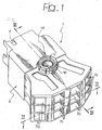
- the reference number 1 designates, as a whole, a structure made of plastic material that can be used as an air distributor in a motor vehicle.
- the structure 1 comprises a main section 2 that defines a main duct 3 for the flow of the air (Figure 3), which enters the duct through an opening 4.
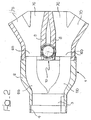
- the main duct 3 divides into two separate ducts 5S, 5D, each of which is prolonged into three main ducts 6S, and three main ducts 6D, respectively, which are set vertically one above another.
- Each of the main ducts 6S branches into two secondary ducts 7S, 7D, which define between them an angle of less than 90° and which exit from the structure 1 at the end opposite to the opening 4.
- each of the three main ducts 6D set vertically one above another branches into two secondary ducts 7C, 7D, which form between them an angle of less than 90°.
- Each of the three main ducts 6S set vertically one above another is delimited on its inner side by a wall 8 having a control opening 9 set in a plane parallel to the direction of flow of the air through the duct 6S.
- each of the three main ducts 6S set vertically one above another is delimited on its inner side by a wall 8 having a control opening 9, which is also set lying in a plane parallel to the direction of flow of the air through the duct 6D.
- the system envisages in all three control openings 9 vertically aligned with one another for controlling the flow of air that passes through the three main ducts 6S, and three control openings 9, which are also vertically aligned with one another for controlling the flow of air that passes through the three main ducts 6D.
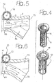
- obturator means consisting of an obturator device 10 including two concentric and rotating cylinders 11, 12 (see Figure 4).
- the walls 11a and 12a of the two cylinders 11, 12 are illustrated, developed in the plane, in Figure 7.
- the said walls have a series of openings 13, which are arranged and shaped in such a way that the different relative positions of the two cylinders 10, 11 provide the different possible combinations of opening and closing of the control openings 9.
- each control opening 9 the open state and the closed state are determining for bringing about deviation of the main air flow towards one or the other secondary duct.
- This phenomenon is illustrated in Figures 5 and 6 with reference to a single specific main duct 6D from which there branch off two secondary ducts 7C, 7D.
- the control opening 9 is obturated in that the internal cylinder 11 has one of its closed walls 11a in a position corresponding to the control opening 9. In this condition, the main flow of air that passes through the main duct 6D flows, by Coanda effect, following the curve of the wall 8, into the secondary duct 7C.
- the two rotating cylinders 11, 12 have toothings 14, 15 respectively, which enable engagement of corresponding operating members.
- the means designed to control rotation of the two cylinders 11, 12 may be of any known type, as has already been described above.
- the device illustrated in the attached drawings is here given purely by way of example. Obviously, the example illustrated presents particular advantages from the points of view of simplicity, reduced overall dimensions, and modularity.
- the obturator device 10 may be controlled by a single actuator, with a very low energy consumption. Thanks to the arrangement described, the head losses in the air ducts are minimal, and this fact guarantees the high efficiency of the air-distribution system.
- Figure 8 illustrates a further example of embodiment, in which the deviation of the air flow that passes through a main duct 20 into a first secondary duct 21 or into a second secondary duct 22 is controlled, according to criteria of bistability, by means of two lateral oscillating fins 23, 24, respectively, which are associated with two respective control openings.
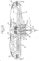
- Figure 9 illustrates the application of a device 1 according to the invention, which has an inlet 3 and eight outlets 50 connected by means of respective pipes 51 and outlet mouths 52.
- the system according to the invention is suited to being used both in motor vehicles and in air-distribution systems for residential, commercial or industrial buildings, or in any other field of use of air-distribution systems (for instance, also in aeroplanes or ships).
- Figures 11-16 illustrate a variant of the assembly of Figure 1.
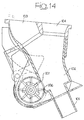
- the body of the distributor assembly designated as a whole by the reference number 100 comprises a plurality of inlet connections 101, which define a passage 102 (Figure 14), which branches into two ducts 103, 104 that give out onto the top face 105 of the assembly.
- a side wall of the inlet duct 102 has an opening 106 controlled by a respective rotating cylinder 107.
- two control cylinders 107 that are mutually coaxial are provided.
- the two cylinders 107 are not concentric, but are set one as the prolongation of the other.
- each of the cylinders 107 ( Figure 10) is mounted so that it can rotate within fins 108 that form part of the structure of the assembly and has a wall with open portions and closed portions having the purpose of controlling the openings 106.
- the movement of the two cylinders 107 is controlled by a single motor assembly set in a casing 109 that forms part of the structure of the assembly and has an output shaft that controls a worm screw 110.
- the worm screw 110 meshes with a gear wheel 111 ( Figure 13), which transmits the rotation by means of a pinion 112 coaxial with a gear wheel 113, which is mounted so that it turns on the structure of the assembly between the two ends facing one another of the two cylinders 107.
- the gear wheel 113 has on its two opposed faces two ratchets 114, 115, respectively, which are connected in rotation with the wheel 113.
- Each ratchet 114, 115 co-operates with elastic elements 116 carried by the respective facing ends 107a of the cylinders 107.
- the electric control motor is a reversible electric motor, designed to cause rotation in one direction or in the other of the gear wheel 113, by means of the transmission 110, 111, 112.
- the gear 113 transmits its rotation to just one of the two cylinders 107 by means of a respective ratchet mechanism made up of one of the two ratchets 114, 115 and of the elastic elements 116 that co-operate with it.
- a respective ratchet mechanism made up of one of the two ratchets 114, 115 and of the elastic elements 116 that co-operate with it.
- one of the two cylinders is driven in rotation - whilst the other cylinder remains stationary - in so far as its respective ratchet can rotate, causing repeated jumps of the respective elastic elements 116.
- reference F designates a flow coming from a duct C which opens out into a chamber V that has a larger section than the section of the duct C and is delimited between two side walls W1, W2 set at different distances from the outlet mouth of the duct C.
- the flow F coming out of the duct C adheres to the wall W1, which is closer to the outlet mouth C.
- Figures 18A,18B show the principle of operation of the arrangement provided at any of ducts 6s or 6d of figure 2. In these figures, the parts that are in common with those of Figure 17 are designated by the same reference numbers.
- the duct C opens out into a chamber V having a wider section than that of the duct C.
- the chamber V is delimited between two opposite walls W1, W2 set at different distances from duct C (see also figure 2, where for example duct 5D opens into a larger duct 6D which has side walls located at different distances from the opening end of duct 5D).
- From the chamber V there originate a first outlet duct E1 and a second outlet duct E2 (as in figure 2 outlet ducts 7D,7C originate from duct 6D).
Landscapes
- Physics & Mathematics (AREA)
- Thermal Sciences (AREA)
- Engineering & Computer Science (AREA)
- Mechanical Engineering (AREA)
- Air-Flow Control Members (AREA)
- Air-Conditioning For Vehicles (AREA)
- Flow Control (AREA)
- Duct Arrangements (AREA)
Applications Claiming Priority (3)
| Application Number | Priority Date | Filing Date | Title |
|---|---|---|---|
| IT2001TO000223A ITTO20010223A1 (it) | 2001-03-12 | 2001-03-12 | Sistema di distribuzione di aria. |
| ITTO20010223 | 2001-03-12 | ||
| PCT/EP2002/002593 WO2002072371A1 (en) | 2001-03-12 | 2002-03-08 | Air-distribution system |
Publications (2)
| Publication Number | Publication Date |
|---|---|
| EP1368207A1 EP1368207A1 (en) | 2003-12-10 |
| EP1368207B1 true EP1368207B1 (en) | 2006-07-19 |
Family
ID=11458675
Family Applications (1)
| Application Number | Title | Priority Date | Filing Date |
|---|---|---|---|
| EP02729980A Expired - Lifetime EP1368207B1 (en) | 2001-03-12 | 2002-03-08 | Air-distribution system |
Country Status (10)
| Country | Link |
|---|---|
| US (1) | US6941967B2 (it) |
| EP (1) | EP1368207B1 (it) |
| JP (1) | JP2004518938A (it) |
| KR (1) | KR20030086241A (it) |
| CN (1) | CN100445116C (it) |
| BR (1) | BR0206029A (it) |
| DE (1) | DE60213212T2 (it) |
| ES (1) | ES2268028T3 (it) |
| IT (1) | ITTO20010223A1 (it) |
| WO (1) | WO2002072371A1 (it) |
Cited By (2)
| Publication number | Priority date | Publication date | Assignee | Title |
|---|---|---|---|---|
| EP2149465A1 (en) * | 2008-07-31 | 2010-02-03 | C.R.F. Società Consortile per Azioni | Motor-vehicle dashboard with main central portion having no outflow apertures for the ventilation air |
| US7815498B2 (en) | 2006-11-08 | 2010-10-19 | C.R.F. Societa Consortile Per Azioni | Device for distribution of air within the passenger compartment of a vehicle |
Families Citing this family (21)
| Publication number | Priority date | Publication date | Assignee | Title |
|---|---|---|---|---|
| ITTO20010619A1 (it) * | 2001-06-27 | 2002-12-27 | Fiat Ricerche | Sistema di distribuzione di aria per un autoveicolo. |
| ITTO20020617A1 (it) * | 2002-07-16 | 2004-01-16 | Fiat Ricerche | Dispositivo di distribuzione di aria per autoveicoli |
| ITTO20030036A1 (it) * | 2003-01-24 | 2004-07-25 | Fiat Ricerche | Sistema di climatizzazione di autoveicolo con dispositivo distributore e miscelatore di aria, ad effetto coanda, avente uscite a temperature differenziate |
| JP2004345363A (ja) * | 2003-03-18 | 2004-12-09 | Calsonic Kansei Corp | 車両用送風ダクト |
| EP1656271B1 (de) * | 2003-08-11 | 2008-01-09 | Behr GmbH & Co. KG | Luftausströmer, insbesondere für ein kraftfahrzeug |
| FR2877271B1 (fr) * | 2004-11-03 | 2007-02-02 | Faurecia Interieur Ind Snc | Aerateur de systeme de ventilation de l'habitacle d'un vehicule |
| DE102005050881B3 (de) * | 2005-10-21 | 2007-02-08 | Faurecia Innenraum Systeme Gmbh | Belüftungseinrichtung für einen Fahrzeuginnenraum |
| ITBO20060281A1 (it) * | 2006-04-13 | 2007-10-14 | Ferrari Spa | Impianto di climatizzazione per un abitacolo di un veicolo |
| FR2909935B1 (fr) * | 2006-12-19 | 2015-04-24 | Renault Sas | Dispositif de climatisation d'un vehicule comportant un reseau de canalisations de degivrage |
| DE102007001986A1 (de) * | 2007-01-08 | 2008-07-10 | Behr Gmbh & Co. Kg | Luftausströmer, insbesondere für ein Kraftfahrzeug |
| KR101479369B1 (ko) * | 2007-09-21 | 2015-01-05 | 에어그린 엘티디. | 공조 시스템들로부터 공기 제트를 방출하고 주위 공기를 혼합시키는 장치 |
| US20100216387A1 (en) * | 2009-02-20 | 2010-08-26 | Ford Global Technologies, Llc | Duct architecture for regulating climate zone in a vehicle |
| US9011216B1 (en) * | 2009-06-02 | 2015-04-21 | The Boeing Company | Diversion directional nozzle |
| DE102013111175B3 (de) * | 2013-10-09 | 2014-09-04 | Dr. Schneider Kunststoffwerke Gmbh | Luftausströmer |
| DE102015109068A1 (de) * | 2015-06-09 | 2016-12-15 | Dr. Ing. H.C. F. Porsche Aktiengesellschaft | Personenanströmer für ein Fahrzeug |
| DE102016225128A1 (de) * | 2016-12-15 | 2018-06-21 | Bayerische Motoren Werke Aktiengesellschaft | Luftausströmer für ein Kraftfahrzeug sowie hiermit ausgestattetes Kraftfahrzeug |
| KR102429172B1 (ko) * | 2016-12-21 | 2022-08-03 | 현대자동차주식회사 | 자동차용 슬림형 에어벤트의 풍향 조절 장치 |
| US20180215237A1 (en) * | 2017-02-01 | 2018-08-02 | GM Global Technology Operations LLC | System and method for hvac outlet flow control vent using electrically responsive vanes |
| DE102019128461A1 (de) * | 2019-10-22 | 2021-04-22 | Mann+Hummel Gmbh | Strömungssystem für Fluide mit einer Umschalteinrichtung |
| KR102686958B1 (ko) * | 2019-11-18 | 2024-07-19 | 현대모비스 주식회사 | 코안다 효과를 이용한 차량용 에어벤트 장치 |
| CN112706584B (zh) * | 2021-01-07 | 2026-02-10 | 蔚来汽车科技(安徽)有限公司 | 出风装置、副仪表台及汽车 |
Family Cites Families (14)
| Publication number | Priority date | Publication date | Assignee | Title |
|---|---|---|---|---|
| US3521653A (en) * | 1967-12-13 | 1970-07-28 | Sperry Rand Corp | Power transmission |
| DE1811286B1 (de) * | 1968-11-27 | 1970-11-19 | Audi Nsu Auto Union Ag | Einrichtung zum Zufuehren von Luft in den Innenraum von Kraftfahrzeugen |
| US3942559A (en) * | 1974-10-10 | 1976-03-09 | Messerschmitt-Bolkow-Blohm Gesellschaft Mit Beschrankter Haftung | Electrofluidic converter |
| JPS5618109A (en) * | 1979-07-24 | 1981-02-20 | Matsushita Electric Ind Co Ltd | Controlling device for direction of flow |
| JPS5674551A (en) * | 1979-11-20 | 1981-06-20 | Nissan Motor Co Ltd | Fluid blowing-off structure |
| JPS56148544U (it) | 1980-04-07 | 1981-11-09 | ||
| US4388950A (en) * | 1980-12-09 | 1983-06-21 | Bowles Fluidics Corporation | Fluid flow control element having movable valve and method |
| JPS6078824A (ja) | 1983-10-07 | 1985-05-04 | Nippon Denso Co Ltd | 空気調和装置の流体吹出口 |
| AU565295B2 (en) * | 1983-10-13 | 1987-09-10 | Matsushita Electric Industrial Co., Ltd. | Fluid deflecting assembly |
| US4686890A (en) | 1984-09-14 | 1987-08-18 | Bowles Fluidics Corporation | Air distribution system |
| JPS6288606A (ja) * | 1985-10-14 | 1987-04-23 | Nippon Denso Co Ltd | 自動車用空気調和装置 |
| JPH06288606A (ja) | 1993-04-02 | 1994-10-18 | Toshiba Corp | 高分子ゲルアクチュエータを用いた流体制御装置 |
| JP3480264B2 (ja) * | 1997-09-18 | 2003-12-15 | 日産自動車株式会社 | ベンチレーテッドロータ |
| DE19820333C2 (de) * | 1998-05-07 | 2001-06-07 | Daimler Chrysler Ag | Belüftungsdüse für Fahrzeuge |
-
2001
- 2001-03-12 IT IT2001TO000223A patent/ITTO20010223A1/it unknown
-
2002
- 2002-03-08 EP EP02729980A patent/EP1368207B1/en not_active Expired - Lifetime
- 2002-03-08 WO PCT/EP2002/002593 patent/WO2002072371A1/en not_active Ceased
- 2002-03-08 ES ES02729980T patent/ES2268028T3/es not_active Expired - Lifetime
- 2002-03-08 KR KR10-2003-7006053A patent/KR20030086241A/ko not_active Ceased
- 2002-03-08 JP JP2002571311A patent/JP2004518938A/ja active Pending
- 2002-03-08 US US10/416,796 patent/US6941967B2/en not_active Expired - Lifetime
- 2002-03-08 DE DE60213212T patent/DE60213212T2/de not_active Expired - Lifetime
- 2002-03-08 CN CNB028029186A patent/CN100445116C/zh not_active Expired - Fee Related
- 2002-03-08 BR BR0206029-9A patent/BR0206029A/pt not_active IP Right Cessation
Cited By (2)
| Publication number | Priority date | Publication date | Assignee | Title |
|---|---|---|---|---|
| US7815498B2 (en) | 2006-11-08 | 2010-10-19 | C.R.F. Societa Consortile Per Azioni | Device for distribution of air within the passenger compartment of a vehicle |
| EP2149465A1 (en) * | 2008-07-31 | 2010-02-03 | C.R.F. Società Consortile per Azioni | Motor-vehicle dashboard with main central portion having no outflow apertures for the ventilation air |
Also Published As
| Publication number | Publication date |
|---|---|
| ES2268028T3 (es) | 2007-03-16 |
| CN1473118A (zh) | 2004-02-04 |
| BR0206029A (pt) | 2003-08-12 |
| CN100445116C (zh) | 2008-12-24 |
| EP1368207A1 (en) | 2003-12-10 |
| DE60213212D1 (de) | 2006-08-31 |
| ITTO20010223A1 (it) | 2002-09-12 |
| US20040055654A1 (en) | 2004-03-25 |
| JP2004518938A (ja) | 2004-06-24 |
| ITTO20010223A0 (it) | 2001-03-12 |
| DE60213212T2 (de) | 2006-12-14 |
| KR20030086241A (ko) | 2003-11-07 |
| WO2002072371A1 (en) | 2002-09-19 |
| US6941967B2 (en) | 2005-09-13 |
Similar Documents
| Publication | Publication Date | Title |
|---|---|---|
| US6941967B2 (en) | Air-distribution system | |
| EP2357101B1 (en) | Sliding door device | |
| JPH11115460A (ja) | 自動車の暖房または空調装置 | |
| US6887148B2 (en) | Air-distribution device for motor vehicles | |
| US5531248A (en) | Butterfly valve | |
| EP1585642B1 (en) | A motor vehicle air conditioning system with an air distributor and mixer device, with coanda effect, having outlets at differentiated temperatures | |
| US4407186A (en) | Flow outlet structure for automotive air conditioner | |
| EP1544004B1 (en) | System for distributing air to a row of seats in the passenger compartment of a means of transport or inside the room of a building | |
| CN102292601B (zh) | 具有交替空气流的通风装置 | |
| ITRM20000164A1 (it) | Impianto di climatizzazione per l'abitacolo di un autoveicolo. | |
| EP3401136A1 (en) | Air distribution device to control the diffusion of an air flow | |
| EP1249670B1 (en) | Air-mixing system using a fluid deflector device of an analogical type | |
| IES990990A2 (en) | An hydraulic drive system | |
| GB2065293A (en) | Fluid outlet structure | |
| EP3536980B1 (en) | Valve body for a servovalve | |
| CN217539701U (zh) | 一种多通道流量分配模块 | |
| US4757744A (en) | Apparatus for controlling flaps in an installation for heating and ventilating or for air-conditioning a motor vehicle | |
| JPH07166890A (ja) | マルチ弁 | |
| JP3601091B2 (ja) | 吹出口切替装置 | |
| CN222255129U (zh) | 一种汽车用冷媒三通比例换向阀 | |
| CN102259571A (zh) | 用于控制至少两道气流的装置 | |
| KR102696317B1 (ko) | 차량용 공조장치 | |
| KR100299796B1 (ko) | 자동차의 공기 조화 장치용 온도 조절 장치 | |
| CN112964076A (zh) | 挡板阀、烟道系统、烟气余热回收系统及排放控制方法 | |
| JPH0226142B2 (it) |
Legal Events
| Date | Code | Title | Description |
|---|---|---|---|
| PUAI | Public reference made under article 153(3) epc to a published international application that has entered the european phase |
Free format text: ORIGINAL CODE: 0009012 |
|
| 17P | Request for examination filed |
Effective date: 20030321 |
|
| AK | Designated contracting states |
Kind code of ref document: A1 Designated state(s): AT BE CH CY DE DK ES FI FR GB GR IE IT LI LU MC NL PT SE TR |
|
| AX | Request for extension of the european patent |
Extension state: AL LT LV MK RO SI |
|
| 17Q | First examination report despatched |
Effective date: 20040504 |
|
| GRAP | Despatch of communication of intention to grant a patent |
Free format text: ORIGINAL CODE: EPIDOSNIGR1 |
|
| GRAS | Grant fee paid |
Free format text: ORIGINAL CODE: EPIDOSNIGR3 |
|
| GRAA | (expected) grant |
Free format text: ORIGINAL CODE: 0009210 |
|
| AK | Designated contracting states |
Kind code of ref document: B1 Designated state(s): DE ES FR GB IT SE |
|
| PG25 | Lapsed in a contracting state [announced via postgrant information from national office to epo] |
Ref country code: IT Free format text: LAPSE BECAUSE OF FAILURE TO SUBMIT A TRANSLATION OF THE DESCRIPTION OR TO PAY THE FEE WITHIN THE PRESCRIBED TIME-LIMIT;WARNING: LAPSES OF ITALIAN PATENTS WITH EFFECTIVE DATE BEFORE 2007 MAY HAVE OCCURRED AT ANY TIME BEFORE 2007. THE CORRECT EFFECTIVE DATE MAY BE DIFFERENT FROM THE ONE RECORDED. Effective date: 20060719 |
|
| REG | Reference to a national code |
Ref country code: GB Ref legal event code: FG4D |
|
| REF | Corresponds to: |
Ref document number: 60213212 Country of ref document: DE Date of ref document: 20060831 Kind code of ref document: P |
|
| REG | Reference to a national code |
Ref country code: SE Ref legal event code: TRGR |
|
| ET | Fr: translation filed | ||
| REG | Reference to a national code |
Ref country code: ES Ref legal event code: FG2A Ref document number: 2268028 Country of ref document: ES Kind code of ref document: T3 |
|
| PLBE | No opposition filed within time limit |
Free format text: ORIGINAL CODE: 0009261 |
|
| STAA | Information on the status of an ep patent application or granted ep patent |
Free format text: STATUS: NO OPPOSITION FILED WITHIN TIME LIMIT |
|
| 26N | No opposition filed |
Effective date: 20070420 |
|
| PGFP | Annual fee paid to national office [announced via postgrant information from national office to epo] |
Ref country code: SE Payment date: 20080306 Year of fee payment: 7 |
|
| PGFP | Annual fee paid to national office [announced via postgrant information from national office to epo] |
Ref country code: ES Payment date: 20080418 Year of fee payment: 7 |
|
| EUG | Se: european patent has lapsed | ||
| REG | Reference to a national code |
Ref country code: ES Ref legal event code: FD2A Effective date: 20090309 |
|
| PG25 | Lapsed in a contracting state [announced via postgrant information from national office to epo] |
Ref country code: ES Free format text: LAPSE BECAUSE OF NON-PAYMENT OF DUE FEES Effective date: 20090309 |
|
| PG25 | Lapsed in a contracting state [announced via postgrant information from national office to epo] |
Ref country code: SE Free format text: LAPSE BECAUSE OF NON-PAYMENT OF DUE FEES Effective date: 20090309 |
|
| REG | Reference to a national code |
Ref country code: FR Ref legal event code: PLFP Year of fee payment: 15 |
|
| REG | Reference to a national code |
Ref country code: FR Ref legal event code: PLFP Year of fee payment: 16 |
|
| REG | Reference to a national code |
Ref country code: FR Ref legal event code: PLFP Year of fee payment: 17 |
|
| PGFP | Annual fee paid to national office [announced via postgrant information from national office to epo] |
Ref country code: GB Payment date: 20180329 Year of fee payment: 17 |
|
| PGFP | Annual fee paid to national office [announced via postgrant information from national office to epo] |
Ref country code: FR Payment date: 20180329 Year of fee payment: 17 Ref country code: IT Payment date: 20180315 Year of fee payment: 17 |
|
| PGFP | Annual fee paid to national office [announced via postgrant information from national office to epo] |
Ref country code: DE Payment date: 20180530 Year of fee payment: 17 |
|
| REG | Reference to a national code |
Ref country code: DE Ref legal event code: R119 Ref document number: 60213212 Country of ref document: DE |
|
| GBPC | Gb: european patent ceased through non-payment of renewal fee |
Effective date: 20190308 |
|
| PG25 | Lapsed in a contracting state [announced via postgrant information from national office to epo] |
Ref country code: GB Free format text: LAPSE BECAUSE OF NON-PAYMENT OF DUE FEES Effective date: 20190308 Ref country code: DE Free format text: LAPSE BECAUSE OF NON-PAYMENT OF DUE FEES Effective date: 20191001 |
|
| PG25 | Lapsed in a contracting state [announced via postgrant information from national office to epo] |
Ref country code: FR Free format text: LAPSE BECAUSE OF NON-PAYMENT OF DUE FEES Effective date: 20190331 Ref country code: IT Free format text: LAPSE BECAUSE OF NON-PAYMENT OF DUE FEES Effective date: 20190308 |