EP1368209B1 - Sicherheitssystem für tank für flüssigen kraftstoff - Google Patents
Sicherheitssystem für tank für flüssigen kraftstoff Download PDFInfo
- Publication number
- EP1368209B1 EP1368209B1 EP02732455A EP02732455A EP1368209B1 EP 1368209 B1 EP1368209 B1 EP 1368209B1 EP 02732455 A EP02732455 A EP 02732455A EP 02732455 A EP02732455 A EP 02732455A EP 1368209 B1 EP1368209 B1 EP 1368209B1
- Authority
- EP
- European Patent Office
- Prior art keywords
- tank
- fuel
- valve
- pipe
- during
- Prior art date
- Legal status (The legal status is an assumption and is not a legal conclusion. Google has not performed a legal analysis and makes no representation as to the accuracy of the status listed.)
- Expired - Lifetime
Links
Images

Classifications
-
- B—PERFORMING OPERATIONS; TRANSPORTING
- B60—VEHICLES IN GENERAL
- B60K—ARRANGEMENT OR MOUNTING OF PROPULSION UNITS OR OF TRANSMISSIONS IN VEHICLES; ARRANGEMENT OR MOUNTING OF PLURAL DIVERSE PRIME-MOVERS IN VEHICLES; AUXILIARY DRIVES FOR VEHICLES; INSTRUMENTATION OR DASHBOARDS FOR VEHICLES; ARRANGEMENTS IN CONNECTION WITH COOLING, AIR INTAKE, GAS EXHAUST OR FUEL SUPPLY OF PROPULSION UNITS IN VEHICLES
- B60K15/00—Arrangement in connection with fuel supply of combustion engines or other fuel consuming energy converters, e.g. fuel cells; Mounting or construction of fuel tanks
- B60K15/01—Arrangement of fuel conduits
-
- B—PERFORMING OPERATIONS; TRANSPORTING
- B60—VEHICLES IN GENERAL
- B60K—ARRANGEMENT OR MOUNTING OF PROPULSION UNITS OR OF TRANSMISSIONS IN VEHICLES; ARRANGEMENT OR MOUNTING OF PLURAL DIVERSE PRIME-MOVERS IN VEHICLES; AUXILIARY DRIVES FOR VEHICLES; INSTRUMENTATION OR DASHBOARDS FOR VEHICLES; ARRANGEMENTS IN CONNECTION WITH COOLING, AIR INTAKE, GAS EXHAUST OR FUEL SUPPLY OF PROPULSION UNITS IN VEHICLES
- B60K15/00—Arrangement in connection with fuel supply of combustion engines or other fuel consuming energy converters, e.g. fuel cells; Mounting or construction of fuel tanks
- B60K15/03—Fuel tanks
- B60K15/035—Fuel tanks characterised by venting means
- B60K15/03504—Fuel tanks characterised by venting means adapted to avoid loss of fuel or fuel vapour, e.g. with vapour recovery systems
-
- B—PERFORMING OPERATIONS; TRANSPORTING
- B60—VEHICLES IN GENERAL
- B60K—ARRANGEMENT OR MOUNTING OF PROPULSION UNITS OR OF TRANSMISSIONS IN VEHICLES; ARRANGEMENT OR MOUNTING OF PLURAL DIVERSE PRIME-MOVERS IN VEHICLES; AUXILIARY DRIVES FOR VEHICLES; INSTRUMENTATION OR DASHBOARDS FOR VEHICLES; ARRANGEMENTS IN CONNECTION WITH COOLING, AIR INTAKE, GAS EXHAUST OR FUEL SUPPLY OF PROPULSION UNITS IN VEHICLES
- B60K15/00—Arrangement in connection with fuel supply of combustion engines or other fuel consuming energy converters, e.g. fuel cells; Mounting or construction of fuel tanks
- B60K15/03—Fuel tanks
- B60K2015/03328—Arrangements or special measures related to fuel tanks or fuel handling
- B60K2015/03447—Arrangements or special measures related to fuel tanks or fuel handling for improving the sealing
-
- B—PERFORMING OPERATIONS; TRANSPORTING
- B60—VEHICLES IN GENERAL
- B60K—ARRANGEMENT OR MOUNTING OF PROPULSION UNITS OR OF TRANSMISSIONS IN VEHICLES; ARRANGEMENT OR MOUNTING OF PLURAL DIVERSE PRIME-MOVERS IN VEHICLES; AUXILIARY DRIVES FOR VEHICLES; INSTRUMENTATION OR DASHBOARDS FOR VEHICLES; ARRANGEMENTS IN CONNECTION WITH COOLING, AIR INTAKE, GAS EXHAUST OR FUEL SUPPLY OF PROPULSION UNITS IN VEHICLES
- B60K15/00—Arrangement in connection with fuel supply of combustion engines or other fuel consuming energy converters, e.g. fuel cells; Mounting or construction of fuel tanks
- B60K15/03—Fuel tanks
- B60K15/04—Tank inlets
- B60K15/0406—Filler caps for fuel tanks
- B60K2015/0451—Sealing means in the closure cap
Definitions
- the present invention relates to a safety system for a liquid fuel tank.
- the invention is directed to a safety system for a fuel tank, that is to say a system that allows the storage and handling of fuel in a safe manner for the user as for the environment.
- a safety system for a fuel tank that is to say a system that allows the storage and handling of fuel in a safe manner for the user as for the environment.
- Such a system protects the user from any hazardous situation, in particular the risk of explosion, implosion, combustion or pollution of any kind, while maintaining the external environment free of any leakage of liquid or emanation. unwanted gases.
- the tank to which the system according to the invention is directed consists of a closed chamber, of various shapes, generally impervious to the outside and may be equipped with various internal accessories or through the wall of the pregnant.
- the tank can hold any type of liquid fuel.
- it may contain fuel for the supply of automotive heat engines and, in particular, gasoline and diesel.
- it can also contain any organic liquid that would be used as a fuel and / or oxidizer for feeding a fuel cell intended to generate an electric current in order to supply one or more engines consuming this type of energy. .
- the system according to the invention can be made of any suitable material used to make a liquid fuel system. Examples of these materials are various metals and plastics. A system according to the invention may also comprise more than one particular material.
- the security system according to the invention is made of plastic.
- plastic is meant any material comprising at least one synthetic resin polymer.
- plastics may be suitable.
- Well-suited plastics belong to the thermoplastics category.
- Thermoplastic means any thermoplastic polymer, including thermoplastic elastomers, and mixtures thereof.
- polymer denotes both homopolymers and copolymers (especially binary or ternary). Examples of such copolymers are, but are not limited to: random copolymers, block copolymers, block copolymers and graft copolymers.
- thermoplastic polymer or copolymer whose melting point is below the decomposition temperature is suitable.
- Synthetic thermoplastics having a melting range spread over at least 10 degrees Celsius are particularly suitable. Examples of such materials are those having a polydispersion of their molecular weight.
- polyolefins polyvinyl halides
- thermoplastic polyesters polyketones
- polyamides polyamides
- a mixture of polymers or copolymers may also be used, as well as a mixture of polymeric materials with fillers inorganic, organic and / or natural such as, for example, but not limited to: carbon, salts and other inorganic derivatives, natural or polymeric fibers.
- multilayer structures consisting of stacked and solid layers comprising at least one of the polymers or copolymers described above.
- Polyvinyl halides and polyolefins are generally preferred.
- a polymer often used is polyethylene. Excellent results have been obtained with high density polyethylene (HDPE).
- HDPE high density polyethylene
- the filler neck of the system according to the invention has the function of allowing the filling of the reservoir, without leakage of liquid, from a point which is not in close proximity to the reservoir. It is for example common, in the case of personal automobiles, that the fuel tank is located in an inaccessible location and connected by a filler neck to a plug-closable orifice located at a place easily accessible from the body of the vehicle. vehicle.
- the filler neck is provided at its inlet with a gun guide provided with a sealing device vis-à-vis the external environment.
- the gun is the one that equips the pumps of service stations for the supply of fuel, including motor vehicles.
- the guide is provided with a sealing device vis-à-vis the external environment.
- This sealing device is capable of isolating the interior atmosphere of the tank and that of the filler neck from the ambient atmosphere, even when the gun is introduced into the tubing and passes through said guide.
- isolated is meant here: admit a slight leak of the order of 12 1 / hour under an overpressure of 40 mbar relative to the atmospheric pressure when the gun is introduced into the guide and, in any case less than 20 1 / hour under the same pressure.
- the liquid fuel volume decreases as more or less regular and / or continuous sampling is made. It is therefore necessary to provide and equip the tanks with devices allowing the entry of air to compensate for the loss of liquid during operation and thus avoid the depression of the tank and the dangers inherent in this situation. .
- the role of the safety valve mounted on a tank is to ensure the venting of the tank, in other words, to allow its programmed opening to perform the two distinct functions of degassing when filling the tank and venting it during normal use during which the fuel contained therein is either consumed or left in the tank for a certain period of storage.
- the safety system for liquid fuel tank comprises a float valve, that is to say a mobile device sliding in a drum, which follows the fuel level present in the tank as soon as this level reaches the low rest position of the float in the drum.
- a valve is a device which, together with the other elements of the safety system, contributes to maintain the tank on which it is mounted in a safe state for the user, that is to say safe from any hazardous situation, in particular the risk of explosion, implosion, combustion or pollution of any kind, while maintaining the external environment safe from liquid leakage or undesirable gases.
- the system according to the invention also comprises a vapor breathing pipe and fixing the maximum level of the liquid fuel in the tank during filling.
- This pipe crosses the upper wall of the tank and dives inside the latter, in its upper part, to a certain level which corresponds to the maximum maximum allowed level of fuel in the full tank.
- the breathing pipe can pass through the upper wall of the tank at any point on the upper surface of the tank. In particular, it can advantageously pass through this wall at a location near or adjacent to the valve.
- the breathing pipe connects the upper part of the tank to the upper part of the filler neck and is able to evacuate most of the volume of gases present in the tank, that is to say has a diameter sufficient to allow the escape of gases without creating substantial overpressure inside the tank.
- This breathing pipe terminates downstream of the sealing device of the gun guide present in the top of the filler neck.
- downstream is used here to mean the side of the sealing device located towards the reservoir.
- the valve is open, in normal situation, during the filling operation of the tank as during the periods of normal use thereof, when it is closed and the fuel is either consumed or abandoned in the tank for a certain period of storage.
- the flotation line of the flapper float is set so that the flap is only closed in two circumstances. The first of these occurs when the tank is tilted beyond a predetermined limit, or is completely returned. The second prevails during a transient fuel movement whose magnitude exceeds a certain predetermined value.
- a float valve that is suitable for the system according to the invention is one with a double chamber, one comprising a float and the other a volume acting as a capacity capable of trapping the liquid fuel entrained by the vapors. escaping from the flapper.
- a valve is described in the French patent application No. 2000.09286 .
- the security system described above is adapted to the various types of geographical location as well as pistols encountered in the service stations that distribute the fuel.
- the sealing device according to the security system according to the invention can be made of any material capable of ensuring good sealing function between the tank and the outside atmosphere, including when the nozzle of a fuel gun passes through it.
- the term "sealing” is understood here as accepting a slight leak, of the same order of magnitude as that described above in the situation where the gun is introduced into the guide.
- a particular embodiment that has given good results is that in which this device is made of flexible elastomer material comprising two elements, the first, on the upstream side, consisting of several circular lips folding on the outside surface of the pipe of the nozzle of the gun and the second, on the downstream side, by a shutter which can open under the effect of the contact pressure of the end of the nozzle of the gun.
- This device with two circular lips gave good results.
- a possible embodiment of the shutter is a flattened circular piece of elastomer material slotted in a star from its center in a number of radii delimiting circular sector-shaped lamellae nevertheless ensuring gastightness when they are in the closed rest position, one against the other.
- a shutter with 4 slats in quarters gave excellent results.
- a first variant of the system according to the invention well suited to guns equipped with fuel vapor suction devices an outlet of the valve is connected, d ' first, a canister filled with fuel vapor absorbing material and a vapor vent pipe connects, on the other hand, a second outlet of the valve to the top of the filler neck, upstream of the sealing device from the guide to a location near the gun suction device.
- This degassing pipe is able to evacuate most of the volume of gases that escape the tank during a filling operation of the latter.
- Such a type of pistol sucking vapors is also called “active" pistol.
- This system is particularly advantageous when the active pistol is of the type equipped with a sleeve suction device capable of surrounding the upper orifice of the tubing through which the filling is performed. This type of pistol can meet more often in Europe than in North America.
- High volatility fuel is understood to mean light fuels such as gasolines of various qualities, excluding heavier oils such as gas oil or other diesel fuel.
- the outputs of the valve in question are, on the one hand, the exit of the gases of the venting circuit during the normal operating periods and, on the other hand, the gas outlet of the degassing circuit during the filling.
- the latter can, for example be located at the gas outlet of the capacity trapping the liquid fuel drives, when such a capacity is installed in the valve used.
- a second variant of the system includes a valve which is also connected to a canister filled with fuel vapor absorbing material.
- the volume of the canister, the size of the valve and the diameter of the pipe connecting the valve to the canister are dimensioned so that the latter is able to evacuate alone most of the volume of gases that escape from the tank during the filling operation.
- the canister in addition to the absorption of gases during the venting of the tank in normal use, the canister also ensures the absorption of gases leaving the tank at the time of filling. This situation can be found mainly in North America.
- a third variant of the system according to the invention adapted to low volatility fuels comprises a valve whose outlet opens into a canister filled with fuel vapor absorbing material.
- the exit of the valve is generally unique. This system can be found in both Europe and North America.
- a fourth variant is that the outlet of the valve opens to the atmosphere without passing through a canister.
- This variant is more particularly adapted to European systems.
- the exit to the atmosphere can be direct on the valve itself. It can also be done through a device preventing the introduction of solid particles into the tank or by any other appropriate device such as a pipe or any evacuation circuit.
- a vapor degassing pipe connects a second outlet of the valve to the upper part of the filler pipe, upstream of the guide sealing device, at a close place a suction device of the gun, and is able to evacuate most of the volume of gas escaping from the tank during a filling operation of the latter.
- degassing pipe also serves to introduce fuel into the tank.
- this pipe extends the filler neck. It can enter the tank at any point on its upper surface. Preferably, it enters the tank through the same opening in the wall of the latter as a pump and / or gauge module.
- the breathing and / or degassing lines generally have a shape introducing a siphon between the reservoir and the head of the filler neck.
- the system of the invention may also include breathing ducts and / or degassing that do not include siphon.
- the invention also relates to a liquid fuel tank for a vehicle which is equipped with a system according to any one of the embodiments detailed above.
- the invention is also addressed to a filler neck plug of a system according to the variants which comprise a degassing pipe connected to the upper part of the filler neck, upstream of the sealing device, whose characteristic is to have at its inner end to the tubular a circular projection capable, when the plug is in the closed position, to close the lip of the flexible gasket upstream and to isolate in a sealed manner the degassing line of the assembly formed by the filler neck and the first channel of vapor respiration. Sealing is understood here for both vapors and liquid fuel.
- a tank (12) of high density polyethylene containing liquid fuel was provided with a filler neck (10), a vent and vent valve (6), having a trapping capacity of liquid (18), connected by the pipe (7) to a canister (8) filled with activated carbon and by a degassing pipe (4) to the upper orifice (3) of the filler neck (10).
- a vapor pipe (19) connected the sky of the tank (12) to a zone (1) of the pipe (10) located immediately downstream of the sealing device (2).
- This sealing device (2) had a flexible seal.
- the breathing pipe (19) penetrated the tank through the same hole as that made in the wall thereof for the valve (6) and plunged into the sky of the tank (12) to a level (5) which fixed the maximum level of liquid fuel allowed in the tank.
- the figure 1 also shows a service station pistol (14) dispensing fuel, engaged in the top of the tubing (10) and passing through the sealing device (2) so that the end (17) of the distributor spout is located downstream of the seal (2).
- the gun (14) was then introduced into the inlet (3) of the tubing (10) and mechanically forced to penetrate the seals of the sealing device (2) and open and pass through the shutter. located at the downstream part of this device.
- This gun (14) carried at the end of its nose (17), introduced into the pipe (10) downstream of the gasket of the sealing device (2), an inlet orifice serving as a trigger sensor of the cutoff the arrival of fuel. Thanks to the seals of the sealing device (2), the ambient air could no longer access the orifice of the triggering system of the gun (14).
- the shutter was opened by the spout (17) which forced the opening of the cut-out cross-shaped wall preventing filling when in the closed position. This arrangement of the shutter has made it possible to force the obtaining of a good position of the gun (14) so as to deliver the fuel into the tank (12) and to position the nozzle (17) of the gun (14) downstream. of the sealing device (2).
- the gun opening control (14) properly positioned in the tubing (10) was then maneuvered by the user and gasoline began to be delivered into the reservoir (12). In such a way that the gun (14) does not trigger or stop the arrival of gasoline, air and / or vapors of gasoline escape through the breathing pipe (19). ), the pipe portion immersing in the reservoir to the level (5), the gas pocket (16), the valve (6), the gas-removal pipe (4) and the atmosphere close to the inlet (3) .
- the gases leaving the atmosphere at the inlet (3) of the tubing were sucked by means of an active system comprising a sleeve (not shown) surrounding the top of the gun (14) and the inlet (3) and connected to a suction pump at the service station where the gases were recovered.
- the fuel level (13) in the tank has risen and has finally flush with the opening of the breathing pipe (19) at level (5).
- the gun (14) has no longer received air or gas from the pocket (16) and the inlet orifice of the spout (17) has been subjected to a slight depression, which has thus caused the activation of the automatic device of the gun (14) responsive to the depression and the triggering of the cut-off of fuel supply.
- valve (6) remained open, the very slight overpressure present in the reservoir during the filling equilibrated with the atmospheric pressure via the degassing pipe (4) and the outlet (3). After closing the cap closing the orifice of the tubing (10), the pressure equalization in the reservoir continued through the pipe (7) and the canister (8).
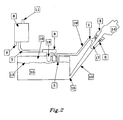
- the figure 2 schematically describes a safety system for a liquid fuel tank in a version suitable for North America.
- a tank (12) of high density polyethylene containing liquid fuel was provided with a filling pipe (10), a vent valve and venting (6), having a capacity liquid trapping device (18), connected via the pipe (7) to a large canister (8) filled with activated carbon.
- a vapor pipe (19) connects the tank top (12) to an area (1) of the tubing (10) immediately downstream of the seal (2). a flexible seal.
- the breathing pipe (19) penetrated the tank through the same hole as that made in the wall thereof for the valve (6) and plunged into the sky of the tank (12) to a level (5) which fixed the maximum level of liquid fuel allowed in the tank.
- the figure 2 also shows a service station pistol (14) dispensing fuel, engaged in the top of the tubing (10) and passing through the sealing device (2) so that the end (17) of the distributor spout is located downstream of the seal (2).
- This spout (17) was pierced with openings (not shown) connected to an external suction device for fuel vapors.
- the operation of the security system of the figure 2 is detailed as follows. Starting from the initial situation in which the tank (12) was closed by a filling plug of the filler neck (10) and the tank in normal situation of rest, no quantity of fuel being taken out, the plug closing the inlet (3) of the filler neck (10), in order to perform a refueling operation.
- the gun (14) was then introduced into the inlet (3) of the tubing (10) and mechanically forced to penetrate the seals of the sealing device (2) and open and pass through the shutter. located at the downstream part of this device.
- This gun (14) carried at the end of its nose (17), introduced into the pipe (10) downstream of the gasket of the sealing device (2), an inlet orifice serving as a trigger sensor of the cutoff the arrival of fuel. Thanks to the seals of the sealing device (2), the ambient air could no longer access the orifice of the triggering system of the gun (14).
- the shutter was opened by the spout (17) which forced the opening of the cut-out cross-shaped wall preventing filling when in the closed position. This arrangement of the shutter has made it possible to force the obtaining of a good position of the gun (14) so as to deliver the fuel into the tank (12) and to position the nozzle (17) of the gun (14) downstream. of the sealing device (2).
- the gun opening control (14) properly positioned in the tubing (10) was then maneuvered by the user and gasoline began to be delivered into the reservoir (12). In such a way that the gun (14) does not trigger or stop the arrival of gasoline, air and / or vapors of gasoline escape through the breathing pipe (19). ), the pipe portion immersing in the reservoir to the level (5), the gas pocket (16), the valve (6), the pipe (7), the canister (8) and the outlet to the atmosphere ( 11).
- the vapors from the bag (16) were evacuated through the breathing pipe (19) from the orifice located at (5), the zone (1) being introduced and the suction holes from the nozzle (17) of the gun (14) (not shown).
- the fuel level (13) in the tank has risen and has finally flush with the opening of the breathing pipe (19) at level (5).
- the gun (14) has no longer received air or gas from the pocket (16) and the inlet orifice of the spout (17) has been subjected to a slight depression, which has thus caused the activation of the automatic device of the gun (14) responsive to the depression and the triggering of the cut-off of fuel supply.
- valve (6) remained open, the very slight overpressure present in the reservoir during the filling equilibrated with the atmospheric pressure via the pipe (7), the canister (8) and the outlet (11).
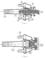
- FIG 3 illustrates the sectional plane of a gun (14) whose spout (17) has been correctly inserted into a sealing device (2) of a pipe (10).
- This device was provided with 2 flexible seals (20) and (21) and a star-shaped shutter with 4 neighborhoods (22). It also distinguishes the arrival (1) of the breathing pipe (19) and the orifice (3) of the degassing pipe (4).
- the figure 4 represents a section in a tubulure - guide - plug assembly in the closed position.
- the projecting end (23) is distinguished from the plug (24) which closes the connection between the filler neck (10) and the degassing pipe (4).
Landscapes
- Engineering & Computer Science (AREA)
- Transportation (AREA)
- Sustainable Development (AREA)
- Sustainable Energy (AREA)
- Chemical & Material Sciences (AREA)
- Combustion & Propulsion (AREA)
- Life Sciences & Earth Sciences (AREA)
- Mechanical Engineering (AREA)
- Cooling, Air Intake And Gas Exhaust, And Fuel Tank Arrangements In Propulsion Units (AREA)
- Feeding And Controlling Fuel (AREA)
- Loading And Unloading Of Fuel Tanks Or Ships (AREA)
- Electrical Discharge Machining, Electrochemical Machining, And Combined Machining (AREA)
- Filling Or Discharging Of Gas Storage Vessels (AREA)
Claims (9)
- Sicherheitssystem für Tank (12) für flüssigen Kraftstoff, mit Folgendem:a) einem an diesem Tank (12) angebrachten Füllrohr (10), das an seiner Eingangsöffnung mit einer Führung für eine Pistole (14) versehen ist, die mit einer Dichtungsvorrichtung (2) gegenüber der äußeren Umgebung versehen ist,b) einem Schwimmerventil (6), das eine in einem Hohlkörper gleitende bewegliche Vorrichtung ist und das dem im Tank (12) vorhandenen Kraftstoffpegel folgt, sobald dieser Pegel die untere Ruheposition des Schwimmers in dem Hohlkörper erreicht, wobei das Ventil an dem Tank (12) angebracht ist, bei einem Füllvorgang dieses Tanks (12) mit Kraftstoff das Entgasen sowie sein Entlüften bei Perioden normaler Verwendung des Tanks (12) gewährleisten kann, beim Füllen des Tanks (12) sowie während Perioden normaler Verwendung des Tanks (12) normalerweise geöffnet ist und eine eingestellte Wasserlinie aufweist, damit das Ventil (6) nur unter zwei Bedingungen geschlossen wird, nämlich wenn der Tank (12) über eine vorbestimmte Grenze hinaus geneigt ist oder sogar vollständig umgedreht ist, und während einer Übergangsbewegung des Kraftstoffes, deren Ausmaß einen vorbestimmten Wert überschreitet;c) einer Leitung (19) zur Entlüftung der Dämpfe und zum Festlegen des maximalen Flüssigkeitspegels im Tank (12) beim Füllen, die einen ausreichend großen Durchmesser aufweist, um die Evakuierung der Gase zu gestatten, ohne einen wesentlichen Überdruck im Inneren des Tanks zu erzeugen, und die im oberen Teil dieses Letzteren eingetaucht ist und diesen oberen Teil stromabwärts der Dichtungsvorrichtung (2) auf der Seite des Tanks (12) mit dem Oberteil des Füllrohrs (10) verbindet.
- System nach Anspruch 1, dadurch gekennzeichnet, dass die Dichtungsvorrichtung (2) aus einem flexiblen elastomeren Material hergestellt ist, das zwei Elemente enthält, wobei das erste auf der stromaufwärtigen Seite aus kreisförmigen Lippen besteht, die auf die Außenseite des Rohrmundstücks (17) der Pistole (14) umgeklappt sind, und das zweite auf der stromabwärtigen Seite aus einem Verschluss besteht, der unter der Wirkung des Kontaktdrucks des Endes des Mundstücks (17) der Pistole (14) geöffnet werden kann.
- System nach einem der Ansprüche 1 oder 2, das für flüssige Kraftstoffe mit hoher Flüchtigkeit und für Pistolen (14), die mit Vorrichtungen zum Ansaugen von Kraftstoffdämpfen versehen sind, geeignet ist, dadurch gekennzeichnet, dass ein Auslass des Ventils (6) einerseits mit einem Behälter (8) verbunden ist, der mit einem die Kraftstoffdämpfe absorbierenden Material gefüllt ist, und dass eine Leitung (4) zur Entlüftung der Dämpfe anderseits einen zweiten Auslass des Ventils (6) stromaufwärts der Dichtungsvorrichtung (2) der Führung an einer Stelle nahe der Saugvorrichtung der Pistole mit dem Oberteil des Füllrohrs (10) verbindet, wobei diese Entlüftungsleitung (4) den Großteil des Volumens der Gase, die bei einem Füllvorgang des Tanks (12) aus dem Tank (12) entweichen, ablassen kann.
- System nach einem der Ansprüche 1 oder 2, das für flüssige Kraftstoffe mit hoher Flüchtigkeit und für Pistolen (14), die nicht mit Vorrichtungen zum Ansaugen von Kraftstoffdämpfen versehen sind, geeignet ist, dadurch gekennzeichnet, dass das Ventil (6) mit einem Behälter (8) verbunden ist, der mit einem die Kraftstoffdämpfe absorbierenden Material gefüllt ist, und dass das Volumen des Behälters (8), die Größe des Ventils (6) und der Durchmesser der Leitung (7), die das Ventil (6) mit dem Behälter (8) verbindet, so bemessen sind, dass der Großteil des Volumens der Gase, die bei einem Füllvorgang aus dem Tank (12) entweichen, abgelassen werden kann.
- System nach einem der Ansprüche 1 oder 2, das für flüssige Kraftstoffe mit geringer Flüchtigkeit geeignet ist, dadurch gekennzeichnet, dass der Auslass des Ventils (6) in einem Behälter (8) mündet, der mit Material gefüllt ist, das die Kraftstoffdämpfe absorbiert.
- System nach einem der Ansprüche 1 oder 2, das für flüssige Kraftstoffe mit geringer Flüchtigkeit geeignet ist, dadurch gekennzeichnet, dass der Auslass des Ventils (6) in der Atmosphäre mündet, ohne durch einen Behälter (8) zu passieren.
- System nach einem der Ansprüche 5 oder 6, dadurch gekennzeichnet, dass eine Leitung (4) zur Entlüftung der Dämpfe einen zweiten Auslass des Ventils (6) stromaufwärts der Dichtungsvorrichtung (2) der Führung an einer Stelle nahe einer Ansaugvorrichtung der Pistole (14) mit dem Oberteil des Füllrohrs (10) verbindet und den Großteil des Volumens der Gase, die beim Füllvorgang des Tanks (12) aus dem Tank (12) entweichen, ablassen kann.
- System nach einem der Ansprüche 3 bis 7, dadurch gekennzeichnet, dass die Entlüftungsleitung (4) des Weiteren dem Einleiten des Kraftstoffes in den Tank (12) dient und durch die gleiche Öffnung in der Wand des Tanks wie ein Pump- und/oder Anzeigemodul in den Tank (12) eintritt.
- Tank (12) für flüssige Kraftstoffe für ein mit einem System nach einem der Ansprüche 1 bis 8 ausgestattetes Fahrzeug.
Applications Claiming Priority (3)
| Application Number | Priority Date | Filing Date | Title |
|---|---|---|---|
| FR0103192 | 2001-03-07 | ||
| FR0103192A FR2821801B1 (fr) | 2001-03-07 | 2001-03-07 | Systeme de securite pour reservoir a carburant liquide |
| PCT/EP2002/002358 WO2002072377A2 (fr) | 2001-03-07 | 2002-03-04 | Systeme de securite pour reservoir a carburant liquide |
Publications (2)
| Publication Number | Publication Date |
|---|---|
| EP1368209A2 EP1368209A2 (de) | 2003-12-10 |
| EP1368209B1 true EP1368209B1 (de) | 2009-05-27 |
Family
ID=8860906
Family Applications (1)
| Application Number | Title | Priority Date | Filing Date |
|---|---|---|---|
| EP02732455A Expired - Lifetime EP1368209B1 (de) | 2001-03-07 | 2002-03-04 | Sicherheitssystem für tank für flüssigen kraftstoff |
Country Status (10)
| Country | Link |
|---|---|
| US (2) | US7152638B2 (de) |
| EP (1) | EP1368209B1 (de) |
| JP (3) | JP2004530587A (de) |
| KR (1) | KR100855932B1 (de) |
| AT (1) | ATE432186T1 (de) |
| AU (1) | AU2002304830A1 (de) |
| BR (1) | BR0207922A (de) |
| DE (1) | DE60232437D1 (de) |
| FR (1) | FR2821801B1 (de) |
| WO (1) | WO2002072377A2 (de) |
Families Citing this family (36)
| Publication number | Priority date | Publication date | Assignee | Title |
|---|---|---|---|---|
| FR2821801B1 (fr) | 2001-03-07 | 2003-07-04 | Inergy Automotive Systems Man | Systeme de securite pour reservoir a carburant liquide |
| FR2844486B1 (fr) * | 2002-09-13 | 2005-05-13 | Inergy Automotive Systems Res | Dispositif d'etancheite et de securite pour le remplissage d'un corps creux avec un liquide |
| FR2844487B1 (fr) * | 2002-09-13 | 2005-05-13 | Inergy Automotive Systems Res | Systeme de securite pour reservoir a carburant liquide |
| FR2861655B1 (fr) | 2003-10-31 | 2006-01-06 | Inergy Automotive Systems Res | Dispositif d'obturation d'une tubulure de remplissage d'un reservoir a liquide, reservoir equipe d'un tel dispositif et vehicule automobile comprenant un tel reservoir |
| FR2886367B1 (fr) * | 2005-05-24 | 2008-12-26 | Inergy Automotive Systems Res | Clapet pour circuit de mise a l'air d'un reservoir a liquide |
| US7886781B2 (en) * | 2005-06-21 | 2011-02-15 | Ameri-Kart Corp. | Spill avoidance system and method |
| US20080041348A1 (en) * | 2006-04-12 | 2008-02-21 | Grant Jeffrey P | Fuel tank with integrated evaporative emissions system |
| US20070261752A1 (en) * | 2006-04-13 | 2007-11-15 | Stant Manufacturing Inc. | Multiple-layer fluid fuel apparatus |
| US7896022B2 (en) * | 2006-06-07 | 2011-03-01 | Eaton Corporation | On-board refueling vapor recovery system with vent line check valve |
| FR2904268B1 (fr) | 2006-07-31 | 2009-04-24 | Inergy Automotive Systems Res | Systeme de remplissage d'un reservoir |
| KR100786535B1 (ko) * | 2007-05-07 | 2007-12-17 | 정호순 | 자동차의 필러 튜브 조립체 |
| DE102008014820A1 (de) | 2007-06-27 | 2009-01-08 | Alfmeier Präzision AG Baugruppen und Systemlösungen | Kraftstofftank für Kraftfahrzeuge |
| KR100838153B1 (ko) * | 2007-08-09 | 2008-06-13 | 주식회사 홈파워 | 스팀청소기용 증기 인출장치 |
| US8056589B2 (en) * | 2008-09-18 | 2011-11-15 | Eaton Corporation | Overfill prevention control for fluid storage container |
| US8464764B1 (en) | 2009-12-07 | 2013-06-18 | Brunswick Corporation | Fuel system ullage float assembly |
| DE102010020581B4 (de) * | 2010-05-14 | 2024-01-25 | Volkswagen Ag | Reduktionsmittelvorratssystem für eine SCR-Abgasanlage |
| DE102011009216B4 (de) * | 2011-01-22 | 2024-03-14 | Volkswagen Aktiengesellschaft | Reduktionsmittelvorratssystem für eine SCR-Abgasanlage |
| KR20130116339A (ko) * | 2011-03-07 | 2013-10-23 | 알프레드 캐르혀 게엠베하 운트 컴파니. 카게 | 가열가능한 고압 클리닝 장치 |
| DE102011013959A1 (de) | 2011-03-14 | 2012-09-20 | Kautex Textron Gmbh & Co. Kg | Druckausgleichsventil für Kraftstoff- oder Nebenflüssigkeitsbehälter an einem KFZ |
| DE102011014713B4 (de) * | 2011-03-23 | 2016-05-19 | Audi Ag | Tankentlüftungsvorrichtung für ein Kraftfahrzeug |
| US8689994B2 (en) | 2011-12-16 | 2014-04-08 | Milton Pashcow | Safety device for a fluid storage tank, related systems and methods |
| FR3014137B1 (fr) * | 2013-12-02 | 2017-07-21 | Inergy Automotive Systems Res (Societe Anonyme) | Systeme de stockage perfectionne d'un additif liquide |
| KR101518938B1 (ko) * | 2013-12-17 | 2015-05-11 | 현대자동차 주식회사 | 자동차의 요소수 통기 장치 |
| DE102015012656B4 (de) * | 2014-10-22 | 2025-07-17 | Audi Ag | Verfahren zum Betreiben einer Kraftstoffanlage für ein Kraftfahrzeug sowie entsprechende Kraftstoffanlage |
| DE102015010354B4 (de) | 2015-08-06 | 2017-03-16 | Audi Ag | Betriebsmitteltankanordnung für ein Kraftfahrzeug |
| CN105599594A (zh) * | 2016-01-29 | 2016-05-25 | 黄社兰 | 油箱加油管 |
| KR101962364B1 (ko) * | 2017-12-26 | 2019-03-26 | 주식회사 한화 | 추진 기관의 구조 시험 장치 및 이를 이용한 추진 기관의 구조 시험 방법 |
| US20200406743A1 (en) * | 2018-01-31 | 2020-12-31 | Plastic Omnium Advanced Innovation And Research | Improved filler head |
| FR3082150B1 (fr) * | 2018-06-11 | 2020-12-18 | Psa Automobiles Sa | Reservoir avec canalisation empechant un passage de carburant liquide vers un dispositif de stockage des vapeurs de carburant |
| DE102018118272A1 (de) * | 2018-07-27 | 2020-01-30 | Kautex Textron Gmbh & Co. Kg | Einfüllstutzen für druckloses Betankungsabschalten und Nachtanken und Betriebsflüssigkeitsbehälter mit Einfüllstutzen |
| EP3738810B1 (de) * | 2019-05-15 | 2021-11-03 | Magna Energy Storage Systems GesmbH | Entlüftungsvorrichtung zur entlüftung eines kraftfahrzeugtanks |
| JP7182514B2 (ja) * | 2019-06-04 | 2022-12-02 | 日産自動車株式会社 | 燃料タンクシステム及び燃料タンクシステムの制御方法 |
| JP7587586B2 (ja) * | 2020-01-31 | 2024-11-20 | プラスチック・オムニウム・アドヴァンスド・イノベーション・アンド・リサーチ | 早期のノズル遮断を回避する充填機ヘッド |
| US11518238B1 (en) * | 2021-10-19 | 2022-12-06 | Ford Global Technologies, Llc | System and method for controlling flow in a fuel recirculation line |
| US11698037B1 (en) | 2022-04-08 | 2023-07-11 | Ford Global Technologies, Llc | Fuel system for a vehicle and method of controlling |
| FR3139102A1 (fr) * | 2022-08-29 | 2024-03-01 | Alstom Holdings | Sablière de véhicule ferroviaire, ensemble et véhicule ferroviaire associés |
Family Cites Families (108)
| Publication number | Priority date | Publication date | Assignee | Title |
|---|---|---|---|---|
| US252958A (en) | 1882-01-31 | Attachment to steam boilers | ||
| US1363263A (en) | 1918-01-23 | 1920-12-28 | Us Light & Heat Corp | Relief mechanism for storage batteries |
| US2352898A (en) | 1941-03-07 | 1944-07-04 | Wright Aeronautical Corp | Engine breather valve |
| US2396233A (en) | 1943-07-20 | 1946-03-12 | Victor R Abrams | Filler cap and relief vent |
| US2845937A (en) | 1953-12-01 | 1958-08-05 | Aero Supply Mfg Co Inc | Aircraft tank vent valve |
| BE567894A (de) | 1957-05-22 | 1900-01-01 | ||
| US3059661A (en) | 1959-09-28 | 1962-10-23 | Holley Carburetor Co | Fuel bowl float |
| US3141469A (en) | 1960-07-29 | 1964-07-21 | Stradella Giuseppe | Eccentric float device for the automatic actuation of the check valve of the breathing pipes of diving masks or the like |
| US3500843A (en) | 1967-10-02 | 1970-03-17 | Charles Eugene White | Fuel tank assembly with gravity vent valve |
| US3545465A (en) | 1967-11-29 | 1970-12-08 | Vapor Corp | Pressure regulator |
| US3643690A (en) | 1969-09-13 | 1972-02-22 | Toyota Motor Co Ltd | Vented fuel tank |
| US3738364A (en) * | 1970-10-01 | 1973-06-12 | Kimberly Clark Co | Compressed tampon with tapered tip |
| US3765435A (en) | 1971-11-10 | 1973-10-16 | Gen Motors Corp | Tank vent control unit |
| US3738384A (en) | 1972-04-03 | 1973-06-12 | Chrysler Corp | Five-way control valve and system |
| US3910302A (en) | 1973-12-14 | 1975-10-07 | Chrysler Corp | Roll-over valve and vapor separator |
| US3907153A (en) | 1974-02-19 | 1975-09-23 | Gen Motors Corp | Fuel tank venting system |
| US4003475A (en) * | 1974-11-27 | 1977-01-18 | Fmc Corporation | Crane boom lattice and hoist line protection assembly |
| US4000828A (en) | 1975-06-02 | 1977-01-04 | Stant Manufacturing Company, Inc. | Gas tank cap with roll-over valving |
| US3994360A (en) | 1975-06-06 | 1976-11-30 | Colt Industries Operating Corporation | Safety shut-off fuel system |
| US3994358A (en) | 1975-06-06 | 1976-11-30 | Colt Industries Operating Corporation | Safety shut-off fuel system |
| US4033475A (en) | 1975-06-09 | 1977-07-05 | Stant Manufacturing Company, Inc. | Roll-over gas cap |
| US3996951A (en) | 1975-11-17 | 1976-12-14 | Parr Manufacturing Inc. | Safety roll over valve |
| US4082169A (en) | 1975-12-12 | 1978-04-04 | Bowles Romald E | Acceleration controlled fluidic shock absorber |
| US4095609A (en) | 1976-09-27 | 1978-06-20 | Chrysler Corporation | Roll-over valve for motor vehicles |
| US4185651A (en) | 1977-06-30 | 1980-01-29 | Paulson Eugene K | Inertially triggered fluid flow control device |
| US4463773A (en) | 1980-11-21 | 1984-08-07 | Yamatake-Honeywell Co., Ltd. | Safety shut-off valve |
| US4351350A (en) | 1981-01-16 | 1982-09-28 | Stant Inc. | Valving assembly for a liquid-containing tank |
| JPS5983124A (ja) * | 1982-11-04 | 1984-05-14 | Yasuto Ozaki | レ−ザビ−ム広角度集光器 |
| JPS60199727A (ja) | 1984-03-24 | 1985-10-09 | Toyota Motor Corp | 車両用燃料タンク |
| US4670749A (en) | 1984-04-13 | 1987-06-02 | Zilog, Inc. | Integrated circuit programmable cross-point connection technique |
| US4598741A (en) * | 1984-09-21 | 1986-07-08 | D. C. Johnson & Associates, Inc. | Barrier vapor control system |
| FR2583353B1 (fr) | 1985-06-14 | 1987-07-24 | Renault | Reservoir a carburant en matiere synthetique, notamment pour vehicule automobile |
| US4646772A (en) | 1985-08-12 | 1987-03-03 | G.T. Products, Inc. | Fuel tank mounted roll-over valve |
| JPS6253224A (ja) | 1985-09-02 | 1987-03-07 | Nissan Motor Co Ltd | 車両用燃料タンクの蒸発燃料流出防止装置 |
| US4669346A (en) * | 1986-03-05 | 1987-06-02 | Roper Whitney Co., Division Of Roper Industries, Inc. | Machine with work positioning carriage |
| US4760858A (en) | 1986-03-07 | 1988-08-02 | Stant Inc. | Fuel vapor control valve |
| US4694847A (en) | 1986-03-07 | 1987-09-22 | Stant Inc. | Roll-over valve with sealing ball |
| US4944779A (en) | 1986-03-31 | 1990-07-31 | Stant Inc. | Vapor recovery system |
| US4770677A (en) | 1986-03-31 | 1988-09-13 | Stant Inc. | Vapor recovery system |
| US4816045A (en) | 1986-03-31 | 1989-03-28 | Stant Inc. | Vapor recovery system |
| US4836835A (en) | 1986-03-31 | 1989-06-06 | Stant Inc. | Vacuum-actuated vapor recovery system |
| US4706708A (en) | 1986-06-23 | 1987-11-17 | General Motors Corporation | Fuel tank venting |
| FR2601929B1 (fr) | 1986-07-23 | 1989-07-28 | Peugeot | Dispositif d'aeration d'un reservoir de carburant |
| US4724861A (en) | 1986-08-18 | 1988-02-16 | General Motors Corporation | Fuel tank venting |
| US4656772A (en) * | 1986-10-10 | 1987-04-14 | Manuel Lopez | Fishing device |
| US4714172A (en) * | 1986-12-23 | 1987-12-22 | Gt Development Corporation | Vapor recovery systems |
| US4872439A (en) | 1987-02-02 | 1989-10-10 | Toyota Jidosha Kabushiki Kaisha | Device for preventing outflow of a fuel vapor from a fuel tank |
| US4874020A (en) | 1987-03-26 | 1989-10-17 | Whitehead Engineered Products, Inc. | System for controlling the release of fuel vapors from a vehicle fuel tank |
| US4813453A (en) | 1987-04-21 | 1989-03-21 | Borg-Warner Automotive, Inc. | Vehicle fuel tank vapor recovery system |
| US4762156A (en) | 1987-07-16 | 1988-08-09 | General Motors Corporaton | Fuel fill vapor recovery system with vapor recirculation |
| JP2604383B2 (ja) * | 1987-08-10 | 1997-04-30 | 日産自動車株式会社 | 自動車用フィラーチューブのベントカットバルブ |
| US4821908A (en) | 1987-09-03 | 1989-04-18 | General Motors Corporation | On-board refueling vapor recovery system |
| US4809863A (en) | 1987-10-16 | 1989-03-07 | Colt Industries Inc | Fill neck assembly for on board refueling vapor recovery system |
| JPH081134Y2 (ja) | 1987-12-09 | 1996-01-17 | オーエム工業株式会社 | 自動車給油管 |
| DE3742256C1 (de) | 1987-12-12 | 1989-03-02 | Daimler Benz Ag | Vorrichtung zum Auffangen von Kraftstoffdaempfen beim Betanken eines Kraftstoffbehaelters |
| US4790349A (en) | 1988-04-04 | 1988-12-13 | Stant Inc. | Tank pressure control system |
| US4917157A (en) | 1989-02-27 | 1990-04-17 | General Motors Corporation | Vehicle tank vapor vent valve assembly |
| US5099880A (en) | 1989-03-24 | 1992-03-31 | Stant Inc. | Fuel tank venting control valve assembly |
| US4966299A (en) | 1989-07-11 | 1990-10-30 | Chrysler Corporation | Fuel assembly having a vapor vent with a hinged float valve |
| US4974645A (en) | 1990-01-09 | 1990-12-04 | Ford Motor Company | Non-expulsive fuel filler assembly |
| US5524662A (en) * | 1990-01-25 | 1996-06-11 | G.T. Products, Inc. | Fuel tank vent system and diaphragm valve for such system |
| US5054508A (en) | 1990-01-25 | 1991-10-08 | G.T. Products, Inc. | Fuel tank vent system and diaphragm valve for such system |
| US4991615A (en) | 1990-03-02 | 1991-02-12 | Stant Inc. | Tank pressure control apparatus |
| US5014742A (en) | 1990-04-05 | 1991-05-14 | General Motors Corporation | Vacuum actuated tank vapor vent valve |
| US5054520A (en) | 1990-04-25 | 1991-10-08 | General Motors Corporation | Remotely actuated fuel tank vapor vent valve |
| WO1991017278A1 (en) * | 1990-05-09 | 1991-11-14 | Lanxide Technology Company, Lp | Barrier materials for making metal matrix composites |
| US5028244A (en) | 1990-06-27 | 1991-07-02 | Stant Inc. | Tank venting control valve assembly |
| US5029722A (en) * | 1990-09-04 | 1991-07-09 | Carter Automotive Company, Inc. | Fuel vapor control system |
| US5065782A (en) | 1991-01-08 | 1991-11-19 | Stant Inc. | Tank venting control assembly |
| JP3055951B2 (ja) * | 1991-01-10 | 2000-06-26 | マツダ株式会社 | 車両の燃料タンク装置 |
| US5156178A (en) | 1991-02-22 | 1992-10-20 | Stant Inc. | Vacuum-actuated vent assembly |
| US5263511A (en) * | 1991-04-18 | 1993-11-23 | Toyoda Gosei Co., Ltd. | Fuel tank for vehicle |
| GB2254846A (en) * | 1991-04-19 | 1992-10-21 | Ford Motor Co | A vent arrangement for a fuel tank |
| US5183087A (en) * | 1991-06-10 | 1993-02-02 | Borg-Warner Automotive Electronic & Mechanical Systems Corporation | Refueling vapor recovery system |
| JP2977657B2 (ja) * | 1991-11-11 | 1999-11-15 | 愛三工業株式会社 | 燃料流出防止装置 |
| US5318069A (en) | 1992-01-17 | 1994-06-07 | Stant Manufacturing Inc. | Tank venting and vapor recovery system |
| JPH05254352A (ja) | 1992-03-12 | 1993-10-05 | Aisan Ind Co Ltd | 車輌用燃料タンクの燃料流出防止装置 |
| JPH05330351A (ja) * | 1992-06-04 | 1993-12-14 | Honda Motor Co Ltd | 車両用燃料タンク |
| JPH0664455A (ja) * | 1992-08-20 | 1994-03-08 | Horie Kinzoku Kogyo Kk | 燃料タンクの燃料蒸気流路開閉制御装置 |
| US5282497A (en) * | 1992-10-23 | 1994-02-01 | Allen Allison | Fuel delivery and vapor control system for controlling the release of fuel vapors from a vehicle fuel tank |
| JPH06156093A (ja) | 1992-11-24 | 1994-06-03 | Aisan Ind Co Ltd | フロート付フューエルカットオフバルブ |
| JP3449955B2 (ja) * | 1992-12-14 | 2003-09-22 | 株式会社ニフコ | 燃料流出防止弁 |
| US5404906A (en) | 1992-12-21 | 1995-04-11 | Nissan Motor Co., Ltd. | Fuel tank |
| JP2562201Y2 (ja) * | 1992-12-21 | 1998-02-10 | キーパー株式会社 | 燃料タンクの給油部構造 |
| EP0648637A1 (de) * | 1993-09-15 | 1995-04-19 | General Motors Corporation | Vorrichtung zum Einfangen von Dämpfen |
| JPH07119556A (ja) * | 1993-10-22 | 1995-05-09 | Honda Motor Co Ltd | 蒸発燃料排出抑制装置 |
| JP2921548B2 (ja) | 1993-12-24 | 1999-07-19 | 本田技研工業株式会社 | 蒸発燃料処理装置 |
| US5449029A (en) | 1994-05-11 | 1995-09-12 | Stant Manufacturing Inc. | Fill limit valve assembly |
| US5570672A (en) * | 1994-07-28 | 1996-11-05 | Mitsubishi Jidosha Kogyo Kabushiki Kaisha | Fuel evaporative emission treatment system |
| US5518018A (en) | 1994-11-14 | 1996-05-21 | Stant Manufacturing Inc. | Fuel tank venting control assembly |
| JP3348568B2 (ja) * | 1994-12-13 | 2002-11-20 | トヨタ自動車株式会社 | 燃料蒸発ガス排出防止装置 |
| JP2937065B2 (ja) * | 1995-03-27 | 1999-08-23 | 三菱自動車工業株式会社 | 燃料貯蔵装置 |
| US5687778A (en) | 1995-05-01 | 1997-11-18 | Stant Manufacturing Inc. | Dual valve tank venting system |
| US5769057A (en) * | 1995-10-09 | 1998-06-23 | Nissan Motor Co., Ltd. | Fuel tank system |
| US5971017A (en) * | 1996-04-16 | 1999-10-26 | Toyota Jidosha Kabushiki Kaisha | Inlet pipe structure |
| JP3395553B2 (ja) * | 1996-12-26 | 2003-04-14 | トヨタ自動車株式会社 | 車両用燃料タンク |
| JPH10213260A (ja) * | 1997-01-30 | 1998-08-11 | Nok Corp | 液体遮断弁装置 |
| US5950655A (en) | 1997-02-04 | 1999-09-14 | G.T. Products, Inc. | Mechanical seal ORVR system and control valve |
| FR2771971B1 (fr) * | 1997-12-08 | 2000-02-25 | Solvay | Circuit de degazage pour reservoir a liquide |
| US6000426A (en) * | 1997-12-19 | 1999-12-14 | Walbro Corporation | Fuel system for reducing fuel vapor |
| JP2000179421A (ja) * | 1998-12-11 | 2000-06-27 | Toyota Motor Corp | フューエルタンクの差圧弁開弁制御装置 |
| JP2000205071A (ja) * | 1999-01-11 | 2000-07-25 | Toyota Motor Corp | フュ―エルカットオフバルブ |
| US6302133B1 (en) * | 1999-11-15 | 2001-10-16 | Honda Giken Kogyo Kabushiki Kaisha | Fuel tank |
| FR2821801B1 (fr) | 2001-03-07 | 2003-07-04 | Inergy Automotive Systems Man | Systeme de securite pour reservoir a carburant liquide |
| JP3714189B2 (ja) * | 2001-04-24 | 2005-11-09 | 日産自動車株式会社 | 給油システム |
| FR2844486B1 (fr) * | 2002-09-13 | 2005-05-13 | Inergy Automotive Systems Res | Dispositif d'etancheite et de securite pour le remplissage d'un corps creux avec un liquide |
| US7198078B2 (en) * | 2003-07-04 | 2007-04-03 | Toyoda Gosei Co., Ltd. | Filler pipe |
| US7055557B1 (en) * | 2005-03-03 | 2006-06-06 | Eaton Corporation | Dual seal filler neck with air relief valve |
-
2001
- 2001-03-07 FR FR0103192A patent/FR2821801B1/fr not_active Expired - Fee Related
-
2002
- 2002-03-04 AT AT02732455T patent/ATE432186T1/de not_active IP Right Cessation
- 2002-03-04 JP JP2002571316A patent/JP2004530587A/ja active Pending
- 2002-03-04 KR KR1020037011723A patent/KR100855932B1/ko not_active Expired - Fee Related
- 2002-03-04 BR BR0207922-4A patent/BR0207922A/pt not_active IP Right Cessation
- 2002-03-04 WO PCT/EP2002/002358 patent/WO2002072377A2/fr not_active Ceased
- 2002-03-04 US US10/471,055 patent/US7152638B2/en not_active Expired - Lifetime
- 2002-03-04 AU AU2002304830A patent/AU2002304830A1/en not_active Abandoned
- 2002-03-04 DE DE60232437T patent/DE60232437D1/de not_active Expired - Lifetime
- 2002-03-04 EP EP02732455A patent/EP1368209B1/de not_active Expired - Lifetime
-
2006
- 2006-11-14 US US11/559,414 patent/US20070068595A1/en not_active Abandoned
-
2008
- 2008-05-28 JP JP2008139788A patent/JP2008201415A/ja not_active Withdrawn
-
2012
- 2012-02-06 JP JP2012023066A patent/JP5589011B2/ja not_active Expired - Fee Related
Also Published As
| Publication number | Publication date |
|---|---|
| KR20030094276A (ko) | 2003-12-11 |
| JP5589011B2 (ja) | 2014-09-10 |
| US7152638B2 (en) | 2006-12-26 |
| EP1368209A2 (de) | 2003-12-10 |
| DE60232437D1 (de) | 2009-07-09 |
| WO2002072377A3 (fr) | 2003-03-20 |
| FR2821801B1 (fr) | 2003-07-04 |
| BR0207922A (pt) | 2004-04-27 |
| KR100855932B1 (ko) | 2008-09-02 |
| FR2821801A1 (fr) | 2002-09-13 |
| ATE432186T1 (de) | 2009-06-15 |
| US20070068595A1 (en) | 2007-03-29 |
| US20040144443A1 (en) | 2004-07-29 |
| JP2012116482A (ja) | 2012-06-21 |
| JP2008201415A (ja) | 2008-09-04 |
| AU2002304830A1 (en) | 2002-09-24 |
| WO2002072377A2 (fr) | 2002-09-19 |
| JP2004530587A (ja) | 2004-10-07 |
Similar Documents
| Publication | Publication Date | Title |
|---|---|---|
| EP1368209B1 (de) | Sicherheitssystem für tank für flüssigen kraftstoff | |
| EP1539520B1 (de) | Sicherheitssystem für flüssigbrennstofftank | |
| EP1539519B1 (de) | Führung eines kraftstoff-füllstützens mit dichtungs- und sicherheitsvorrichtung | |
| EP1172306B1 (de) | Entlüftungssystem für Flüssigkeitstank | |
| FR2896568A1 (fr) | Dispositif pour circuit de mise a l'air d'un reservoir a liquide et clapet integrant ledit dispositif | |
| FR2770464A1 (fr) | Appareil de controle de vapeurs d'un reservoir de carburant | |
| BE1012697A3 (fr) | Reservoir a carburant. | |
| FR2739612A1 (fr) | Appareil de commande de vapeurs de reservoir de carcurant d'un vehicule | |
| FR2886367A1 (fr) | Clapet pour circuit de mise a l'air d'un reservoir a liquide | |
| EP0962684B1 (de) | Sicherheitsventil für einen Flüssigkeitsbehälter | |
| FR2905442A1 (fr) | Clapet pour circuit de mise a l'air d'un reservoir a liquide | |
| FR2768970A1 (fr) | Tube de remplissage pour reservoir de carburant d'un vehicule | |
| FR2904268A1 (fr) | Systeme de remplissage d'un reservoir | |
| BE1032668B1 (fr) | Vessie pour reservoir a carburant | |
| FR2927024A1 (fr) | Systeme de remplissage d'un reservoir | |
| FR2731185A1 (fr) | Dispositif de remplissage pour un reservoir de carburant muni d'une vanne empechant le refoulement de vapeurs de carburant vers l'atmosphere | |
| FR2908088A1 (fr) | Systeme de remplissage d'un reservoir | |
| FR2918610A1 (fr) | Systeme de remplissage d'un reservoir. |
Legal Events
| Date | Code | Title | Description |
|---|---|---|---|
| PUAI | Public reference made under article 153(3) epc to a published international application that has entered the european phase |
Free format text: ORIGINAL CODE: 0009012 |
|
| 17P | Request for examination filed |
Effective date: 20031007 |
|
| AK | Designated contracting states |
Kind code of ref document: A2 Designated state(s): AT BE CH CY DE DK ES FI FR GB GR IE IT LI LU MC NL PT SE TR |
|
| AX | Request for extension of the european patent |
Extension state: AL LT LV MK RO SI |
|
| 17Q | First examination report despatched |
Effective date: 20051117 |
|
| GRAP | Despatch of communication of intention to grant a patent |
Free format text: ORIGINAL CODE: EPIDOSNIGR1 |
|
| GRAS | Grant fee paid |
Free format text: ORIGINAL CODE: EPIDOSNIGR3 |
|
| GRAA | (expected) grant |
Free format text: ORIGINAL CODE: 0009210 |
|
| AK | Designated contracting states |
Kind code of ref document: B1 Designated state(s): AT BE CH CY DE DK ES FI FR GB GR IE IT LI LU MC NL PT SE TR |
|
| REG | Reference to a national code |
Ref country code: GB Ref legal event code: FG4D Free format text: NOT ENGLISH |
|
| REG | Reference to a national code |
Ref country code: CH Ref legal event code: EP |
|
| REG | Reference to a national code |
Ref country code: IE Ref legal event code: FG4D Free format text: LANGUAGE OF EP DOCUMENT: FRENCH |
|
| REF | Corresponds to: |
Ref document number: 60232437 Country of ref document: DE Date of ref document: 20090709 Kind code of ref document: P |
|
| PG25 | Lapsed in a contracting state [announced via postgrant information from national office to epo] |
Ref country code: AT Free format text: LAPSE BECAUSE OF FAILURE TO SUBMIT A TRANSLATION OF THE DESCRIPTION OR TO PAY THE FEE WITHIN THE PRESCRIBED TIME-LIMIT Effective date: 20090527 Ref country code: PT Free format text: LAPSE BECAUSE OF FAILURE TO SUBMIT A TRANSLATION OF THE DESCRIPTION OR TO PAY THE FEE WITHIN THE PRESCRIBED TIME-LIMIT Effective date: 20090927 Ref country code: FI Free format text: LAPSE BECAUSE OF FAILURE TO SUBMIT A TRANSLATION OF THE DESCRIPTION OR TO PAY THE FEE WITHIN THE PRESCRIBED TIME-LIMIT Effective date: 20090527 |
|
| NLV1 | Nl: lapsed or annulled due to failure to fulfill the requirements of art. 29p and 29m of the patents act | ||
| PG25 | Lapsed in a contracting state [announced via postgrant information from national office to epo] |
Ref country code: NL Free format text: LAPSE BECAUSE OF FAILURE TO SUBMIT A TRANSLATION OF THE DESCRIPTION OR TO PAY THE FEE WITHIN THE PRESCRIBED TIME-LIMIT Effective date: 20090527 Ref country code: SE Free format text: LAPSE BECAUSE OF FAILURE TO SUBMIT A TRANSLATION OF THE DESCRIPTION OR TO PAY THE FEE WITHIN THE PRESCRIBED TIME-LIMIT Effective date: 20090827 |
|
| REG | Reference to a national code |
Ref country code: IE Ref legal event code: FD4D |
|
| PG25 | Lapsed in a contracting state [announced via postgrant information from national office to epo] |
Ref country code: IE Free format text: LAPSE BECAUSE OF FAILURE TO SUBMIT A TRANSLATION OF THE DESCRIPTION OR TO PAY THE FEE WITHIN THE PRESCRIBED TIME-LIMIT Effective date: 20090527 Ref country code: DK Free format text: LAPSE BECAUSE OF FAILURE TO SUBMIT A TRANSLATION OF THE DESCRIPTION OR TO PAY THE FEE WITHIN THE PRESCRIBED TIME-LIMIT Effective date: 20090527 Ref country code: ES Free format text: LAPSE BECAUSE OF FAILURE TO SUBMIT A TRANSLATION OF THE DESCRIPTION OR TO PAY THE FEE WITHIN THE PRESCRIBED TIME-LIMIT Effective date: 20090907 |
|
| PLBE | No opposition filed within time limit |
Free format text: ORIGINAL CODE: 0009261 |
|
| STAA | Information on the status of an ep patent application or granted ep patent |
Free format text: STATUS: NO OPPOSITION FILED WITHIN TIME LIMIT |
|
| 26N | No opposition filed |
Effective date: 20100302 |
|
| PGFP | Annual fee paid to national office [announced via postgrant information from national office to epo] |
Ref country code: FR Payment date: 20100324 Year of fee payment: 9 |
|
| PGFP | Annual fee paid to national office [announced via postgrant information from national office to epo] |
Ref country code: DE Payment date: 20100312 Year of fee payment: 9 |
|
| BERE | Be: lapsed |
Owner name: INERGY AUTOMOTIVE SYSTEMS RESEARCH (SA) Effective date: 20100331 |
|
| PG25 | Lapsed in a contracting state [announced via postgrant information from national office to epo] |
Ref country code: GR Free format text: LAPSE BECAUSE OF FAILURE TO SUBMIT A TRANSLATION OF THE DESCRIPTION OR TO PAY THE FEE WITHIN THE PRESCRIBED TIME-LIMIT Effective date: 20090828 Ref country code: MC Free format text: LAPSE BECAUSE OF NON-PAYMENT OF DUE FEES Effective date: 20100331 |
|
| REG | Reference to a national code |
Ref country code: CH Ref legal event code: PL |
|
| GBPC | Gb: european patent ceased through non-payment of renewal fee |
Effective date: 20100304 |
|
| PG25 | Lapsed in a contracting state [announced via postgrant information from national office to epo] |
Ref country code: LI Free format text: LAPSE BECAUSE OF NON-PAYMENT OF DUE FEES Effective date: 20100331 Ref country code: CH Free format text: LAPSE BECAUSE OF NON-PAYMENT OF DUE FEES Effective date: 20100331 Ref country code: BE Free format text: LAPSE BECAUSE OF NON-PAYMENT OF DUE FEES Effective date: 20100331 |
|
| PG25 | Lapsed in a contracting state [announced via postgrant information from national office to epo] |
Ref country code: GB Free format text: LAPSE BECAUSE OF NON-PAYMENT OF DUE FEES Effective date: 20100304 Ref country code: IT Free format text: LAPSE BECAUSE OF FAILURE TO SUBMIT A TRANSLATION OF THE DESCRIPTION OR TO PAY THE FEE WITHIN THE PRESCRIBED TIME-LIMIT Effective date: 20090527 |
|
| REG | Reference to a national code |
Ref country code: FR Ref legal event code: ST Effective date: 20111130 |
|
| PG25 | Lapsed in a contracting state [announced via postgrant information from national office to epo] |
Ref country code: DE Free format text: LAPSE BECAUSE OF NON-PAYMENT OF DUE FEES Effective date: 20111001 Ref country code: FR Free format text: LAPSE BECAUSE OF NON-PAYMENT OF DUE FEES Effective date: 20110331 |
|
| REG | Reference to a national code |
Ref country code: DE Ref legal event code: R119 Ref document number: 60232437 Country of ref document: DE Effective date: 20111001 |
|
| PG25 | Lapsed in a contracting state [announced via postgrant information from national office to epo] |
Ref country code: CY Free format text: LAPSE BECAUSE OF FAILURE TO SUBMIT A TRANSLATION OF THE DESCRIPTION OR TO PAY THE FEE WITHIN THE PRESCRIBED TIME-LIMIT Effective date: 20090527 |
|
| PG25 | Lapsed in a contracting state [announced via postgrant information from national office to epo] |
Ref country code: LU Free format text: LAPSE BECAUSE OF NON-PAYMENT OF DUE FEES Effective date: 20100304 |
|
| PG25 | Lapsed in a contracting state [announced via postgrant information from national office to epo] |
Ref country code: TR Free format text: LAPSE BECAUSE OF FAILURE TO SUBMIT A TRANSLATION OF THE DESCRIPTION OR TO PAY THE FEE WITHIN THE PRESCRIBED TIME-LIMIT Effective date: 20090527 |