EP1369090A1 - Navigations-Kalibrierung medizinischer Instrumente bzw. Implantate - Google Patents
Navigations-Kalibrierung medizinischer Instrumente bzw. Implantate Download PDFInfo
- Publication number
- EP1369090A1 EP1369090A1 EP02011600A EP02011600A EP1369090A1 EP 1369090 A1 EP1369090 A1 EP 1369090A1 EP 02011600 A EP02011600 A EP 02011600A EP 02011600 A EP02011600 A EP 02011600A EP 1369090 A1 EP1369090 A1 EP 1369090A1
- Authority
- EP
- European Patent Office
- Prior art keywords
- calibration
- instrument
- implant
- section
- spatial orientation
- Prior art date
- Legal status (The legal status is an assumption and is not a legal conclusion. Google has not performed a legal analysis and makes no representation as to the accuracy of the status listed.)
- Granted
Links
Images


Classifications
-
- A—HUMAN NECESSITIES
- A61—MEDICAL OR VETERINARY SCIENCE; HYGIENE
- A61B—DIAGNOSIS; SURGERY; IDENTIFICATION
- A61B90/00—Instruments, implements or accessories specially adapted for surgery or diagnosis and not covered by any of the groups A61B1/00 - A61B50/00, e.g. for luxation treatment or for protecting wound edges
- A61B90/36—Image-producing devices or illumination devices not otherwise provided for
-
- A—HUMAN NECESSITIES
- A61—MEDICAL OR VETERINARY SCIENCE; HYGIENE
- A61B—DIAGNOSIS; SURGERY; IDENTIFICATION
- A61B34/00—Computer-aided surgery; Manipulators or robots specially adapted for use in surgery
- A61B34/20—Surgical navigation systems; Devices for tracking or guiding surgical instruments, e.g. for frameless stereotaxis
-
- A—HUMAN NECESSITIES
- A61—MEDICAL OR VETERINARY SCIENCE; HYGIENE
- A61B—DIAGNOSIS; SURGERY; IDENTIFICATION
- A61B17/00—Surgical instruments, devices or methods
- A61B2017/00681—Aspects not otherwise provided for
- A61B2017/00725—Calibration or performance testing
-
- A—HUMAN NECESSITIES
- A61—MEDICAL OR VETERINARY SCIENCE; HYGIENE
- A61B—DIAGNOSIS; SURGERY; IDENTIFICATION
- A61B34/00—Computer-aided surgery; Manipulators or robots specially adapted for use in surgery
- A61B34/20—Surgical navigation systems; Devices for tracking or guiding surgical instruments, e.g. for frameless stereotaxis
- A61B2034/2046—Tracking techniques
- A61B2034/2055—Optical tracking systems
-
- A—HUMAN NECESSITIES
- A61—MEDICAL OR VETERINARY SCIENCE; HYGIENE
- A61B—DIAGNOSIS; SURGERY; IDENTIFICATION
- A61B34/00—Computer-aided surgery; Manipulators or robots specially adapted for use in surgery
- A61B34/20—Surgical navigation systems; Devices for tracking or guiding surgical instruments, e.g. for frameless stereotaxis
- A61B2034/2068—Surgical navigation systems; Devices for tracking or guiding surgical instruments, e.g. for frameless stereotaxis using pointers, e.g. pointers having reference marks for determining coordinates of body points
Definitions
- the present invention relates to navigation calibration of non-rotationally symmetric, medical instruments or implants.
- Modern, computer-assisted surgery is capable of providing instruments during surgery or implants of the surgeon on a monitor in relation to anatomical data previously obtained from a patient scan (CT, MR).
- CT patient scan
- MR patient scan
- the instruments or the Implants must be calibrated.
- pre-calibration pre-operative calibration
- the navigation system in advance the geometric data of the instrument or the implant to make known and software side to save firmly.
- intra-operative calibration at which the instrument or implant during the operation of the treating Personnel is calibrated.
- intra-operative calibration lies in the fact that existing instruments can be used and one does not depend on the instruments whose geometry has already been stored on the software side is. In other words, every surgeon can use his own instruments, for example.
- An intra-operative calibration is very important even when instruments are between have changed two operations (for example by regrinding an instrument), however, must be calibrated with high accuracy during the operation.
- Intra-operative calibration can be done in several ways.
- a calibration type According to the prior art, only a so-called point calibration is performed, d. H. only the length of the instrument or implant is determined, but not its length Geometry.
- a second and advanced method is, in addition to the length of the exact vector of the instrument, d. H. to determine its geometry.
- Methods and tools used but currently all on rotationally symmetric Limit instruments that are very easy to calibrate.
- complex Instruments and implants for optimal use in medical treatment can be calibrated.
- the method according to the present invention for the calibration or registration of medical Instruments or implants is one of its kind according to a, in which a spatial Position of the instrument or the implant by means of a medical navigation system is determined to the relative position of the instrument or the implant against anatomical To determine data.
- a spatial Position of the instrument or the implant by means of a medical navigation system is determined to the relative position of the instrument or the implant against anatomical To determine data.
- an information about a top position or a single displayed spatial direction not is sufficient to integrate the instrument or the implant optimally in the navigation is
- the spatial orientation of a multi-dimensional designed, functional portion of the instrument or the implant determined.
- a multi-dimensional calibration of the instrument determines the location of a plane or an edge of the instrument, if this is of a functional nature, so if it is for the function of the instrument or the implant depends on how this plane or edge is arranged in space.
- Calibration according to the invention also as a calibration of non-rotationally symmetric Designate instruments or implants, and the particular advantage of the invention is based in that an optimized navigation of such instruments and implants is made possible, what also the final result, for example, the correct creation of a surface section with an instrument or the correct insertion of an implant.
- the spatial orientation of a linear, functional section of the instrument or of the implant is the spatial orientation of a linear, functional section of the instrument or of the implant. If as an instrument, for example, a surgical chisel too It is advantageous to use the spatial orientation of the cutting surface of this chisel to investigate.
- the method according to the present invention is a appropriate portion of the instrument or implant at a calibration section aligned a calibration tool, its spatial orientation in the navigation system is known and is tracked. It may in particular be the functional section itself, which is aligned with the calibration aid or its calibration section in which, in one embodiment, this calibration section is a line shape may have, in particular a line groove.
- the cutting surface of a surgical chisel can be aligned for example in such a line groove.
- the above-mentioned calibration section can be used in the context of the present invention but also be a level on the calibration tool.
- the spatial orientation the multi-dimensionally designed, functional section of the instrument or the Implant with the help of existing information on the orientation of a particular other, characteristic line or plane for the instrument or implant.
- the inventive device for calibration or registration of medical instruments implants includes a medical navigation system, and a calibration tool, wherein the calibration aid has a calibration section, whose spatial orientation is known in the navigation system and in which a multidimensional aligned hentationeller section of the instrument or the implant can be.
- the calibration section is one which has a line shape, in particular the shape of a line groove, while according to another embodiment, a calibration section is provided becomes, which is a plane.
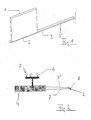
- Figure 1 is shown how the spatial orientation of the cutting surface of a surgical Chisels can be calibrated according to the invention.
- the chisel 1 has a cutting surface 2 on. If, for example, a bone structure is severed with this chisel it is important in some cases that the interface has a certain orientation, especially if special at this separation surface Devices are to be attached, whose orientation is important again. Is to it is necessary in the context of navigation to know the orientation of the cutting surface 2, and as part of the calibration, such a determination can be made, for example, by that the chisel 1 with its cutting surface 2 in the groove 3 'of the groove-shaped Kalibri mecanicsinstrumentes 3 is used, as shown in principle in Figure 1.
- the chisel 4 shown there has a cutting edge 7 with a Cutting surface 2.
- the plane in which the cutting surface 2 is located is denoted by the reference numeral 8 indicated.
- a navigation reference 5 On the chisel is a navigation reference 5, in this case a Referencing adapter with three reflectors, arranged, its location in the navigation system can be determined via cameras. This also determines the level 6, which is parallel to the plane 8 is aligned.
- the geometry of the instrument can now be compared to anatomical data from the computer of the navigation system and displayed on an image output.
- a calibration tool 12 is used to calculate the To determine geometry of the chisel 4 and in particular its cutting surface 2 in space.
- the referencing device 5 is not primarily needed here, it is therefore in schieier Situation shown.
- the calibration aid 12 has a plane 9 whose position in Space is known.
- the determination of the geometry of the Chisel in the room with the help of a known plane outside the chisel, taking after a Alignment of the bit, so for example, a laying of the cutting edge 2 on the known level 9, the calculation of the position of the level 8 can be done, which is the cutting surface 2 whose spatial direction is determined, for example, by a method, as described with reference to FIG.
- the spatial orientation of the Chisel 1 determined by a scanning method.
- the navigation system is already the Geometry of an instrument, for example a pointer 11 shown here schematically. known and this information is now to calibrate the chisel 1 and its Cutting surface 2 used.
- the pointer 11 becomes indefinite with its tip or brought to previously specified points of the chisel 1. Such a point of contact the tip of the pointer 11 with the chisel is shown in FIG. 4 by the reference numeral 10 indicated.
- the dashed lines indicate that with the pointer 11 also other points be approached.
- the approached points are recognized by the navigation system and used to determine the orientation of the chisel in space and as a starting point to save for navigation. As part of the navigation then this known spatial orientation of the bit 1 in relation to other information (for example Anatomy of the patient).
- FIG. 5 shows a functional part of a device according to the invention Calibration instrument, which is designated by the reference numeral 20.
- Another Part of the calibration instrument, which is also provided together with the part 20 is shown in Figure 7 and provided with the reference numeral 21.
- the instrument part 20 has a V-groove 14 bounded by the Nutebenen 15 and 16 becomes. Furthermore, a stop 17 is still provided on the right side of the instrument part 20.
- the front part in Figure 6 by the reference numeral 22 is designated.
- the bit has the cutting edge 2 on the edge vector 18 (peak vector) and a handle portion 23 with the axis vector 19th
- the instrument part 21 of the calibration instrument which is shown in FIG Functional elements have a recess defined by the planes A, B and C, wherein the Plane A is lowered parallel to the surface and planes B and C are perpendicular stand on top of each other and perpendicular to each other. Also, the chisel 22 is hinted.
- the cutting edge 2 of the bit becomes placed in a groove whose direction in space is known, for example, in the groove 14 of the instrument part 20 or in the section line of the planes A and B of the instrument part 21, the is also known (for example, not shown reflector arrangements).
- the cutting edge 2 of the bit is exactly in the groove 14 and at the edge between level A and level B, and geometry data of the calibration element are used for the calibration. Correct positioning of the bit relative to Calibration instrument 20, 21 is assumed.
- the rotation axis can be calculated and calculated with the position determined by the Grooving be adjusted. At about correct positioning (maintained threshold) become the geometry data of the calibration means used for calibration.
- cutting planes can be calibrated, when the bit, as that shown in Figure 2, has inclined surfaces, the Further also be referred to as cutting planes. It should be noted how the Cutting planes lie and at what angle they intersect.
- the chisel will be with his Cutting surfaces in two successive calibration steps to one of the planes, for Example level A, created.
- the cutting planes can be calibrated. When the cutting planes in a very acute angle to each other (infinitely thin chisel) is sufficient Circumstances the calibration of a cutting plane.
- the device according to the invention or the method according to the invention can be but also calibrate other properties of the chisel, for example, the width of his Cutting Edge 2.
- the width of the cutting surface 2 can be determined in their angle to each other, so here it is possible to also determine the width of the cutting surface 2 equal, namely, when - as shown in Figure 7 - the cutting edge 2 at the same time in the attack against the level C is created.
- a two-time application of the chisel of Each flat side then allows the calculation of the chisel width or the position of the axis vector 19 of the handle 23.
- a calibration of the chisel grip piece 23 is also using the V-groove 14th possible, which is shown on the instrument part 20 in Figure 5:
- the calibration of the axis vector 19 and the radius of the chisel grip section takes place by insertion into the V-groove 14 and performing a continuous rotational movement around the axis of rotation of the chisel.
- a fixed reference to the instrument (reflector arrangement) provides the tracking system with continuous data (samples). These will matched by computer aided graphics processing on a cylinder.
- the cylinder has initially any radius. Its axis, however, is parallel to the V-groove 14 and on the plane passing through the V-groove 14 and perpendicular to it, the V-groove opening angle halved vector is spanned.
- the initially variable radius of the Cylinder is after optimized match (for example, least square error, Standard deviation as plausibility check) the calibrated radius of the rotationally symmetric Part.
- optimized match for example, least square error, Standard deviation as plausibility check
- the calibrated radius of the rotationally symmetric Part can be done with the help of a manually entered Radius in case of another cylinder match the accuracy of the calibration of the vector.
- the chisel grip portion 23 is then calibrated, can by means of the already described above Technology, d. H. with the help of a lateral stop (level C in Figure 7), the bit width calibrated, with only one side of the edge of the blade must abut the plane C, since the axis vector 19 is known. With the above step, all necessary calibrations are now made on the instrument.
- a spanned by a reference (reflector adapter) Plane (for example, plane 6 in FIG. 2) parallel to the vector 8, 18 of the cutting edge 2, may be due to the individual calibration of the cutting edge orientation in space be waived.
- the axis vector 19 of the handle portion 23 be calibrated in conjunction with its length, for example, by the use of the stop 17 is possible, which is shown in Figure 5.
- the location and orientation of the edge vector 18 in space is then calculated by the predetermined parallelism to the reference plane (reference 5, Figure 2) plane spanned 6 and from the Axial vector 19 of the instrument, the edge vector 18 at a vertical angle cuts.
- the length of the cutting edge is then entered either manually or by Creation at the boundary plane C ( Figure 7) determined as described above.
Landscapes
- Health & Medical Sciences (AREA)
- Surgery (AREA)
- Life Sciences & Earth Sciences (AREA)
- Engineering & Computer Science (AREA)
- Molecular Biology (AREA)
- Animal Behavior & Ethology (AREA)
- Veterinary Medicine (AREA)
- Biomedical Technology (AREA)
- Heart & Thoracic Surgery (AREA)
- Medical Informatics (AREA)
- Nuclear Medicine, Radiotherapy & Molecular Imaging (AREA)
- Public Health (AREA)
- General Health & Medical Sciences (AREA)
- Pathology (AREA)
- Oral & Maxillofacial Surgery (AREA)
- Robotics (AREA)
- Surgical Instruments (AREA)
- Image Processing (AREA)
- Measuring And Recording Apparatus For Diagnosis (AREA)
- Apparatus For Radiation Diagnosis (AREA)
Abstract
Description
- Figur 1
- die Kalibrierung eines chirurgischen Meißels mittels einer Kalibrierungsnut;
- Figur 2
- die Kalibrierung eines chirurgischen Meißels mit Hilfe einer bekannten Ebene;
- Figur 3
- die Kalibrierung eines chirurgischen Meißels mit Hilfe einer Kalibrierungsebene an einem Kalibrierungshilfsmittel;
- Figur 4
- die Kalibrierung eines chirurgischen Meißels mit Hilfe eines bereits registrierten Instruments; und
- Figuren 5 bis 7
- Darstellungen zur erfindungsgemäßen Kalibrierung, die eine konkrete Ausführungsform erläutern.
Claims (15)
- Verfahren zur Kalibrierung bzw. Registrierung medizinischer Instrumente (1, 4) bzw. Implantate, bei dem eine räumliche Position des Instruments (1, 4) bzw. des Implantats mittels eines medizinischen Navigationssystems ermittelt wird, um die Relativposition des Instruments (1, 4) bzw. des Implantats gegenüber anatomischen Daten zu ermitteln, dadurch gekennzeichnet, dass die räumliche Ausrichtung eines mehrdimensional ausgestalteten, funktionellen Abschnitts (2) des Instruments (1, 4) bzw. des Implantats ermittelt wird.
- Verfahren nach Anspruch 1, bei dem die räumliche Ausrichtung eines linienförmigen, funktionellen Abschnitts (2) des Instruments (1, 4) bzw. des Implantats ermittelt wird.
- Verfahren nach Anspruch 2, bei dem die räumliche Ausrichtung der Schneidenfläche (2) eines chirurgischen Meißels (1, 4) ermittelt wird.
- Verfahren nach einem der Ansprüche 1 bis 3, bei dem ein geeigneter Abschnitt des Instruments (1) bzw. des Implantats an einem Kalibrierungsabschnitt (3', 9) eines Kalibrierungshilfsmittels (3, 12) ausgerichtet wird, dessen räumliche Ausrichtung im Navigationssystem bekannt ist.
- Verfahren nach Anspruch 4, bei dem der funktionelle Abschnitt (2) an dem Kalibrierungshilfsmittel (3, 9) bzw. an dessen Kalibrierungsabschnitt (3', 9) ausgerichtet wird.
- Verfahren nach Anspruch 5, bei dem der Kalibrierungsabschnitt eine Linienform, insbesondere die Form einer Liniennut aufweist.
- Verfahren nach Anspruch 5, bei dem der Kalibrierungsabschnitt eine Ebene ist. '
- Verfahren nach einem der Ansprüche 1 bis 3, bei dem die räumliche Ausrichtung des mehrdimensional ausgestalteten, funktionellen Abschnitts (2) des Instruments (4) bzw. des Implantats mit Hilfe schon vorhandener Informationen über die Ausrichtung einer bestimmten anderen charakteristischen Linie oder Ebene (6) für das Instrument (4) bzw. das Implantat ermittelt wird.
- Verfahren nach einem der Ansprüche 1 bis 3, bei dem die räumliche Ausrichtung des mehrdimensional ausgestalteten, funktionellen Abschnitts (2) des Instruments (1) bzw. des Implantats mit Hilfe der Registrierung mehrerer Punkte auf dem Instrument (1) bzw. Implantat durch ein schon kalibriertes Registrierungsinstrument (11) ermittelt wird.
- Vorrichtung zur Kalibrierung bzw. Registrierung medizinischer Instrumente (1, 4) bzw. Implantate mit einem medizinischen Navigationssystem, mit einem Kalibrierungshilfsmittel (3, 12), dadurch gekennzeichnet, dass das Kalibrierungshilfsmittel einen Kalibrierungsabschnitt (3', 9) aufweist, dessen räumliche Ausrichtung im Navigationssystem bekannt ist und an dem ein mehrdimensional ausgestalteter, funktioneller Abschnitts (2) des Instruments (1, 4) bzw. des Implantats ausgerichtet werden kann.
- Vorrichtung nach Anspruch 10, dadurch gekennzeichnet, dass der Kalibrierungsabschnitt eine Linienform, insbesondere die Form einer Liniennut aufweist.
- Vorrichtung nach Anspruch 10, dadurch gekennzeichnet, dass der Kalibrierungsabschnitt eine Ebene ist.
- Vorrichtung nach Anspruch 10, dadurch gekennzeichnet, dass der Kalibrierungsabschnitt mehrere Begrenzungsebenen und die von diesen eingeschlossenen Schnittlinien oder Schnittpunkte aufweist.
- Programm, das, wenn es auf einem Computer läuft oder in einem Computer geladen ist, den Computer veranlasst, ein Verfahren gemäß einem der Ansprüche 1 bis 9 durchzuführen.
- Computerprogramm-Speichermedium, das ein Programm nach Anspruch 14 aufweist.
Priority Applications (4)
| Application Number | Priority Date | Filing Date | Title |
|---|---|---|---|
| AT02011600T ATE491403T1 (de) | 2002-05-28 | 2002-05-28 | Navigations-kalibrierung medizinischer instrumente bzw. implantate |
| EP02011600A EP1369090B1 (de) | 2002-05-28 | 2002-05-28 | Navigations-Kalibrierung medizinischer Instrumente bzw. Implantate |
| DE50214813T DE50214813D1 (de) | 2002-05-28 | 2002-05-28 | Navigations-Kalibrierung medizinischer Instrumente bzw. Implantate |
| US10/446,649 US7213598B2 (en) | 2002-05-28 | 2003-05-28 | Navigation-calibrating rotationally asymmetrical medical instruments or implants |
Applications Claiming Priority (1)
| Application Number | Priority Date | Filing Date | Title |
|---|---|---|---|
| EP02011600A EP1369090B1 (de) | 2002-05-28 | 2002-05-28 | Navigations-Kalibrierung medizinischer Instrumente bzw. Implantate |
Publications (2)
| Publication Number | Publication Date |
|---|---|
| EP1369090A1 true EP1369090A1 (de) | 2003-12-10 |
| EP1369090B1 EP1369090B1 (de) | 2010-12-15 |
Family
ID=29433083
Family Applications (1)
| Application Number | Title | Priority Date | Filing Date |
|---|---|---|---|
| EP02011600A Expired - Lifetime EP1369090B1 (de) | 2002-05-28 | 2002-05-28 | Navigations-Kalibrierung medizinischer Instrumente bzw. Implantate |
Country Status (3)
| Country | Link |
|---|---|
| EP (1) | EP1369090B1 (de) |
| AT (1) | ATE491403T1 (de) |
| DE (1) | DE50214813D1 (de) |
Cited By (5)
| Publication number | Priority date | Publication date | Assignee | Title |
|---|---|---|---|---|
| EP1570801A1 (de) * | 2004-03-03 | 2005-09-07 | Zimmer Technology, Inc. | Implantatregistriereinrichtung für chirurgische Navigationssysteme |
| US9002432B2 (en) | 2004-11-15 | 2015-04-07 | Brainlab Ag | Method and device for calibrating a medical instrument |
| WO2015117644A1 (en) * | 2014-02-05 | 2015-08-13 | Brainlab Ag | Identification and calibration method |
| US10449005B2 (en) | 2013-03-20 | 2019-10-22 | Brainlab Ag | Adaptor for receiving a navigated structure which is at least a part of a medical object and method of registering a navigated structure using the adaptor |
| US12076093B2 (en) | 2020-09-30 | 2024-09-03 | Brainlab Ag | Method of calibrating a spinal cage |
Citations (3)
| Publication number | Priority date | Publication date | Assignee | Title |
|---|---|---|---|---|
| US6112113A (en) * | 1997-07-03 | 2000-08-29 | U.S. Philips Corporation | Image-guided surgery system |
| WO2001067979A1 (en) * | 2000-03-15 | 2001-09-20 | Orthosoft Inc. | Automatic calibration system for computer-aided surgical instruments |
| US20010034530A1 (en) * | 2000-01-27 | 2001-10-25 | Malackowski Donald W. | Surgery system |
Family Cites Families (1)
| Publication number | Priority date | Publication date | Assignee | Title |
|---|---|---|---|---|
| US5921992A (en) * | 1997-04-11 | 1999-07-13 | Radionics, Inc. | Method and system for frameless tool calibration |
-
2002
- 2002-05-28 AT AT02011600T patent/ATE491403T1/de active
- 2002-05-28 EP EP02011600A patent/EP1369090B1/de not_active Expired - Lifetime
- 2002-05-28 DE DE50214813T patent/DE50214813D1/de not_active Expired - Lifetime
Patent Citations (3)
| Publication number | Priority date | Publication date | Assignee | Title |
|---|---|---|---|---|
| US6112113A (en) * | 1997-07-03 | 2000-08-29 | U.S. Philips Corporation | Image-guided surgery system |
| US20010034530A1 (en) * | 2000-01-27 | 2001-10-25 | Malackowski Donald W. | Surgery system |
| WO2001067979A1 (en) * | 2000-03-15 | 2001-09-20 | Orthosoft Inc. | Automatic calibration system for computer-aided surgical instruments |
Cited By (6)
| Publication number | Priority date | Publication date | Assignee | Title |
|---|---|---|---|---|
| US6988009B2 (en) | 2003-02-04 | 2006-01-17 | Zimmer Technology, Inc. | Implant registration device for surgical navigation system |
| EP1570801A1 (de) * | 2004-03-03 | 2005-09-07 | Zimmer Technology, Inc. | Implantatregistriereinrichtung für chirurgische Navigationssysteme |
| US9002432B2 (en) | 2004-11-15 | 2015-04-07 | Brainlab Ag | Method and device for calibrating a medical instrument |
| US10449005B2 (en) | 2013-03-20 | 2019-10-22 | Brainlab Ag | Adaptor for receiving a navigated structure which is at least a part of a medical object and method of registering a navigated structure using the adaptor |
| WO2015117644A1 (en) * | 2014-02-05 | 2015-08-13 | Brainlab Ag | Identification and calibration method |
| US12076093B2 (en) | 2020-09-30 | 2024-09-03 | Brainlab Ag | Method of calibrating a spinal cage |
Also Published As
| Publication number | Publication date |
|---|---|
| ATE491403T1 (de) | 2011-01-15 |
| DE50214813D1 (de) | 2011-01-27 |
| EP1369090B1 (de) | 2010-12-15 |
Similar Documents
| Publication | Publication Date | Title |
|---|---|---|
| EP1413258B1 (de) | Vorrichtung und Verfahren zum Kalibrieren eines Elements | |
| EP3954312B3 (de) | Chirurgisches instrumtent | |
| EP1932483B1 (de) | Medizinische Einrichtung zur Lagebestimmung von intrakorporalen Implantaten | |
| DE60119890T2 (de) | Handfixierungsvorrichtung | |
| EP2103270B1 (de) | System für navigations-unterstützte Schulteroperationen zur Positionierung navigierter Behandlungsgeräte bezüglich eines Knochens | |
| DE69112538T2 (de) | Computerunterstützte chirurgische Vorrichtung. | |
| DE19534136B4 (de) | Externer oder interner Fixateur zur Wiederherstellung des Skeletts bei Brüchen oder Arthroplastiken | |
| DE102007053058B3 (de) | Chirurgische Sägelehre sowie Sägelehrensatz | |
| DE68924114T2 (de) | Führungsinstrument zum Durchbohren der Knochenrinde, geeignet zum Auffinden der Löcher von Marknägeln. | |
| EP1348383A1 (de) | Retraktornavigation | |
| DE102007011568A1 (de) | Medizinische Klemme, insbesondere Wirbelsäulen-Klemme | |
| CH695846A5 (de) | Chirurgischer Instrumentensatz für die Scarfosteotomie. | |
| DE102008023760A1 (de) | Anordnung zur Bestimmung der Position und Lage eines an einem Objekt befindlichen Merkmals | |
| EP2135575A1 (de) | Instrumentenausrichtungsverfahren mit freier Referenz | |
| EP3090687A1 (de) | Einführungs- und positioniervorrichtung für punktionsnadeln, zugehöriger bausatz und zugehörige verfahren | |
| EP1354562B1 (de) | Knochenfixierungssystem | |
| WO2007095917A2 (de) | Justier- und führungssystem für werkzeuge | |
| EP1369090B1 (de) | Navigations-Kalibrierung medizinischer Instrumente bzw. Implantate | |
| DE10343826B4 (de) | Knochenfester Lokator und Navigationssystem | |
| EP1675520A1 (de) | Vorrichtung zur platzierung von instrumenten oder implantaten in körperorgane | |
| DE102005047895B4 (de) | Verfahren und Einrichtung zur Bestimmung der Lage eines Gegenstandes | |
| EP2258290B1 (de) | Humerusnagel zur Versorgung von Frakturen des Humerus | |
| EP1648318B1 (de) | Vorrichtung zur fixierung eines längsträgers mit einem knochenfixationselement | |
| EP3095398B1 (de) | Patientenspezifisches instrument zur referenzierung von körperteilen | |
| EP3753501A1 (de) | Schablone und sets für eine domosteotomie |
Legal Events
| Date | Code | Title | Description |
|---|---|---|---|
| PUAI | Public reference made under article 153(3) epc to a published international application that has entered the european phase |
Free format text: ORIGINAL CODE: 0009012 |
|
| 17P | Request for examination filed |
Effective date: 20020528 |
|
| AK | Designated contracting states |
Kind code of ref document: A1 Designated state(s): AT BE CH CY DE DK ES FI FR GB GR IE IT LI LU MC NL PT SE TR |
|
| AX | Request for extension of the european patent |
Extension state: AL LT LV MK RO SI |
|
| 17Q | First examination report despatched |
Effective date: 20040202 |
|
| AKX | Designation fees paid |
Designated state(s): AT BE CH CY DE DK ES FI FR GB GR IE IT LI LU MC NL PT SE TR |
|
| APBN | Date of receipt of notice of appeal recorded |
Free format text: ORIGINAL CODE: EPIDOSNNOA2E |
|
| APBR | Date of receipt of statement of grounds of appeal recorded |
Free format text: ORIGINAL CODE: EPIDOSNNOA3E |
|
| APAF | Appeal reference modified |
Free format text: ORIGINAL CODE: EPIDOSCREFNE |
|
| APBT | Appeal procedure closed |
Free format text: ORIGINAL CODE: EPIDOSNNOA9E |
|
| RAP1 | Party data changed (applicant data changed or rights of an application transferred) |
Owner name: BRAINLAB AG |
|
| GRAP | Despatch of communication of intention to grant a patent |
Free format text: ORIGINAL CODE: EPIDOSNIGR1 |
|
| GRAS | Grant fee paid |
Free format text: ORIGINAL CODE: EPIDOSNIGR3 |
|
| GRAA | (expected) grant |
Free format text: ORIGINAL CODE: 0009210 |
|
| AK | Designated contracting states |
Kind code of ref document: B1 Designated state(s): AT BE CH CY DE DK ES FI FR GB GR IE IT LI LU MC NL PT SE TR |
|
| REG | Reference to a national code |
Ref country code: CH Ref legal event code: EP Ref country code: GB Ref legal event code: FG4D Free format text: NOT ENGLISH |
|
| REG | Reference to a national code |
Ref country code: IE Ref legal event code: FG4D |
|
| REF | Corresponds to: |
Ref document number: 50214813 Country of ref document: DE Date of ref document: 20110127 Kind code of ref document: P |
|
| REG | Reference to a national code |
Ref country code: NL Ref legal event code: VDEP Effective date: 20101215 |
|
| PG25 | Lapsed in a contracting state [announced via postgrant information from national office to epo] |
Ref country code: SE Free format text: LAPSE BECAUSE OF FAILURE TO SUBMIT A TRANSLATION OF THE DESCRIPTION OR TO PAY THE FEE WITHIN THE PRESCRIBED TIME-LIMIT Effective date: 20101215 Ref country code: CY Free format text: LAPSE BECAUSE OF FAILURE TO SUBMIT A TRANSLATION OF THE DESCRIPTION OR TO PAY THE FEE WITHIN THE PRESCRIBED TIME-LIMIT Effective date: 20101215 Ref country code: NL Free format text: LAPSE BECAUSE OF FAILURE TO SUBMIT A TRANSLATION OF THE DESCRIPTION OR TO PAY THE FEE WITHIN THE PRESCRIBED TIME-LIMIT Effective date: 20101215 Ref country code: FI Free format text: LAPSE BECAUSE OF FAILURE TO SUBMIT A TRANSLATION OF THE DESCRIPTION OR TO PAY THE FEE WITHIN THE PRESCRIBED TIME-LIMIT Effective date: 20101215 |
|
| REG | Reference to a national code |
Ref country code: IE Ref legal event code: FD4D |
|
| PG25 | Lapsed in a contracting state [announced via postgrant information from national office to epo] |
Ref country code: PT Free format text: LAPSE BECAUSE OF FAILURE TO SUBMIT A TRANSLATION OF THE DESCRIPTION OR TO PAY THE FEE WITHIN THE PRESCRIBED TIME-LIMIT Effective date: 20110415 Ref country code: IE Free format text: LAPSE BECAUSE OF FAILURE TO SUBMIT A TRANSLATION OF THE DESCRIPTION OR TO PAY THE FEE WITHIN THE PRESCRIBED TIME-LIMIT Effective date: 20101215 Ref country code: ES Free format text: LAPSE BECAUSE OF FAILURE TO SUBMIT A TRANSLATION OF THE DESCRIPTION OR TO PAY THE FEE WITHIN THE PRESCRIBED TIME-LIMIT Effective date: 20110326 Ref country code: GR Free format text: LAPSE BECAUSE OF FAILURE TO SUBMIT A TRANSLATION OF THE DESCRIPTION OR TO PAY THE FEE WITHIN THE PRESCRIBED TIME-LIMIT Effective date: 20110316 |
|
| PLBE | No opposition filed within time limit |
Free format text: ORIGINAL CODE: 0009261 |
|
| STAA | Information on the status of an ep patent application or granted ep patent |
Free format text: STATUS: NO OPPOSITION FILED WITHIN TIME LIMIT |
|
| PG25 | Lapsed in a contracting state [announced via postgrant information from national office to epo] |
Ref country code: DK Free format text: LAPSE BECAUSE OF FAILURE TO SUBMIT A TRANSLATION OF THE DESCRIPTION OR TO PAY THE FEE WITHIN THE PRESCRIBED TIME-LIMIT Effective date: 20101215 |
|
| 26N | No opposition filed |
Effective date: 20110916 |
|
| BERE | Be: lapsed |
Owner name: BRAINLAB A.G. Effective date: 20110531 |
|
| PG25 | Lapsed in a contracting state [announced via postgrant information from national office to epo] |
Ref country code: MC Free format text: LAPSE BECAUSE OF NON-PAYMENT OF DUE FEES Effective date: 20110531 Ref country code: IT Free format text: LAPSE BECAUSE OF FAILURE TO SUBMIT A TRANSLATION OF THE DESCRIPTION OR TO PAY THE FEE WITHIN THE PRESCRIBED TIME-LIMIT Effective date: 20101215 |
|
| REG | Reference to a national code |
Ref country code: CH Ref legal event code: PL |
|
| REG | Reference to a national code |
Ref country code: DE Ref legal event code: R097 Ref document number: 50214813 Country of ref document: DE Effective date: 20110916 |
|
| PG25 | Lapsed in a contracting state [announced via postgrant information from national office to epo] |
Ref country code: CH Free format text: LAPSE BECAUSE OF NON-PAYMENT OF DUE FEES Effective date: 20110531 Ref country code: LI Free format text: LAPSE BECAUSE OF NON-PAYMENT OF DUE FEES Effective date: 20110531 |
|
| PG25 | Lapsed in a contracting state [announced via postgrant information from national office to epo] |
Ref country code: BE Free format text: LAPSE BECAUSE OF NON-PAYMENT OF DUE FEES Effective date: 20110531 |
|
| REG | Reference to a national code |
Ref country code: AT Ref legal event code: MM01 Ref document number: 491403 Country of ref document: AT Kind code of ref document: T Effective date: 20110528 |
|
| PG25 | Lapsed in a contracting state [announced via postgrant information from national office to epo] |
Ref country code: AT Free format text: LAPSE BECAUSE OF NON-PAYMENT OF DUE FEES Effective date: 20110528 |
|
| PG25 | Lapsed in a contracting state [announced via postgrant information from national office to epo] |
Ref country code: LU Free format text: LAPSE BECAUSE OF NON-PAYMENT OF DUE FEES Effective date: 20110528 |
|
| PG25 | Lapsed in a contracting state [announced via postgrant information from national office to epo] |
Ref country code: TR Free format text: LAPSE BECAUSE OF FAILURE TO SUBMIT A TRANSLATION OF THE DESCRIPTION OR TO PAY THE FEE WITHIN THE PRESCRIBED TIME-LIMIT Effective date: 20101215 |
|
| REG | Reference to a national code |
Ref country code: DE Ref legal event code: R082 Ref document number: 50214813 Country of ref document: DE Representative=s name: SCHWABE SANDMAIR MARX, DE |
|
| REG | Reference to a national code |
Ref country code: DE Ref legal event code: R081 Ref document number: 50214813 Country of ref document: DE Owner name: BRAINLAB AG, DE Free format text: FORMER OWNER: BRAINLAB AG, 85622 FELDKIRCHEN, DE Effective date: 20131104 Ref country code: DE Ref legal event code: R082 Ref document number: 50214813 Country of ref document: DE Representative=s name: SCHWABE SANDMAIR MARX, DE Effective date: 20131104 Ref country code: DE Ref legal event code: R082 Ref document number: 50214813 Country of ref document: DE Representative=s name: SCHWABE SANDMAIR MARX PATENTANWAELTE RECHTSANW, DE Effective date: 20131104 |
|
| REG | Reference to a national code |
Ref country code: FR Ref legal event code: PLFP Year of fee payment: 15 |
|
| REG | Reference to a national code |
Ref country code: DE Ref legal event code: R082 Ref document number: 50214813 Country of ref document: DE Representative=s name: SCHWABE SANDMAIR MARX PATENTANWAELTE RECHTSANW, DE Ref country code: DE Ref legal event code: R081 Ref document number: 50214813 Country of ref document: DE Owner name: BRAINLAB AG, DE Free format text: FORMER OWNER: BRAINLAB AG, 85622 FELDKIRCHEN, DE Ref country code: DE Ref legal event code: R082 Ref document number: 50214813 Country of ref document: DE Representative=s name: SSM SANDMAIR PATENTANWAELTE RECHTSANWALT PARTN, DE |
|
| REG | Reference to a national code |
Ref country code: FR Ref legal event code: PLFP Year of fee payment: 16 |
|
| REG | Reference to a national code |
Ref country code: FR Ref legal event code: CA Effective date: 20170706 |
|
| REG | Reference to a national code |
Ref country code: FR Ref legal event code: PLFP Year of fee payment: 17 |
|
| PGFP | Annual fee paid to national office [announced via postgrant information from national office to epo] |
Ref country code: DE Payment date: 20210520 Year of fee payment: 20 Ref country code: FR Payment date: 20210520 Year of fee payment: 20 |
|
| PGFP | Annual fee paid to national office [announced via postgrant information from national office to epo] |
Ref country code: GB Payment date: 20210520 Year of fee payment: 20 |
|
| REG | Reference to a national code |
Ref country code: DE Ref legal event code: R071 Ref document number: 50214813 Country of ref document: DE |
|
| REG | Reference to a national code |
Ref country code: GB Ref legal event code: PE20 Expiry date: 20220527 |
|
| PG25 | Lapsed in a contracting state [announced via postgrant information from national office to epo] |
Ref country code: GB Free format text: LAPSE BECAUSE OF EXPIRATION OF PROTECTION Effective date: 20220527 |