EP1369242B1 - Farbstrahlaufzeichnungsgerät und Reinigungsteil - Google Patents
Farbstrahlaufzeichnungsgerät und Reinigungsteil Download PDFInfo
- Publication number
- EP1369242B1 EP1369242B1 EP03012791A EP03012791A EP1369242B1 EP 1369242 B1 EP1369242 B1 EP 1369242B1 EP 03012791 A EP03012791 A EP 03012791A EP 03012791 A EP03012791 A EP 03012791A EP 1369242 B1 EP1369242 B1 EP 1369242B1
- Authority
- EP
- European Patent Office
- Prior art keywords
- cap
- carriage
- recording head
- ink
- recording apparatus
- Prior art date
- Legal status (The legal status is an assumption and is not a legal conclusion. Google has not performed a legal analysis and makes no representation as to the accuracy of the status listed.)
- Expired - Lifetime
Links
- 238000004140 cleaning Methods 0.000 title claims description 101
- 230000007246 mechanism Effects 0.000 claims description 110
- 238000003491 array Methods 0.000 claims description 32
- 238000007599 discharging Methods 0.000 claims description 27
- 239000000463 material Substances 0.000 claims description 24
- 230000003213 activating effect Effects 0.000 claims description 7
- 239000000976 ink Substances 0.000 description 155
- 238000010276 construction Methods 0.000 description 20
- 238000012545 processing Methods 0.000 description 10
- 230000009471 action Effects 0.000 description 7
- 230000001360 synchronised effect Effects 0.000 description 5
- 230000000694 effects Effects 0.000 description 4
- 238000011084 recovery Methods 0.000 description 4
- 230000008901 benefit Effects 0.000 description 3
- 238000009835 boiling Methods 0.000 description 3
- POIUWJQBRNEFGX-XAMSXPGMSA-N cathelicidin Chemical compound C([C@@H](C(=O)N[C@@H](CCCNC(N)=N)C(=O)N[C@@H](CCCCN)C(=O)N[C@@H](CO)C(=O)N[C@@H](CCCCN)C(=O)N[C@@H](CCC(O)=O)C(=O)N[C@@H](CCCCN)C(=O)N[C@@H]([C@@H](C)CC)C(=O)NCC(=O)N[C@@H](CCCCN)C(=O)N[C@@H](CCC(O)=O)C(=O)N[C@@H](CC=1C=CC=CC=1)C(=O)N[C@@H](CCCCN)C(=O)N[C@@H](CCCNC(N)=N)C(=O)N[C@@H]([C@@H](C)CC)C(=O)N[C@@H](C(C)C)C(=O)N[C@@H](CCC(N)=O)C(=O)N[C@@H](CCCNC(N)=N)C(=O)N[C@@H]([C@@H](C)CC)C(=O)N[C@@H](CCCCN)C(=O)N[C@@H](CC(O)=O)C(=O)N[C@@H](CC=1C=CC=CC=1)C(=O)N[C@@H](CC(C)C)C(=O)N[C@@H](CCCNC(N)=N)C(=O)N[C@@H](CC(N)=O)C(=O)N[C@@H](CC(C)C)C(=O)N[C@@H](C(C)C)C(=O)N1[C@@H](CCC1)C(=O)N[C@@H](CCCNC(N)=N)C(=O)N[C@@H]([C@@H](C)O)C(=O)N[C@@H](CCC(O)=O)C(=O)N[C@@H](CO)C(O)=O)NC(=O)[C@H](CC=1C=CC=CC=1)NC(=O)[C@H](CC(O)=O)NC(=O)CNC(=O)[C@H](CC(C)C)NC(=O)[C@@H](N)CC(C)C)C1=CC=CC=C1 POIUWJQBRNEFGX-XAMSXPGMSA-N 0.000 description 3
- 239000007788 liquid Substances 0.000 description 3
- 238000007789 sealing Methods 0.000 description 3
- 238000011144 upstream manufacturing Methods 0.000 description 3
- 238000013459 approach Methods 0.000 description 2
- 230000003247 decreasing effect Effects 0.000 description 2
- 238000000034 method Methods 0.000 description 2
- 230000004044 response Effects 0.000 description 2
- 230000005540 biological transmission Effects 0.000 description 1
- 230000008859 change Effects 0.000 description 1
- 238000004891 communication Methods 0.000 description 1
- 230000008602 contraction Effects 0.000 description 1
- 230000001419 dependent effect Effects 0.000 description 1
- 238000011161 development Methods 0.000 description 1
- 230000018109 developmental process Effects 0.000 description 1
- 230000007774 longterm Effects 0.000 description 1
- 239000002184 metal Substances 0.000 description 1
- 239000000203 mixture Substances 0.000 description 1
- 238000011017 operating method Methods 0.000 description 1
- 238000005192 partition Methods 0.000 description 1
- 230000000149 penetrating effect Effects 0.000 description 1
- 238000007639 printing Methods 0.000 description 1
- 230000008569 process Effects 0.000 description 1
- 238000007711 solidification Methods 0.000 description 1
- 230000008023 solidification Effects 0.000 description 1
- 125000006850 spacer group Chemical group 0.000 description 1
- 230000000087 stabilizing effect Effects 0.000 description 1
Images





Classifications
-
- B—PERFORMING OPERATIONS; TRANSPORTING
- B41—PRINTING; LINING MACHINES; TYPEWRITERS; STAMPS
- B41J—TYPEWRITERS; SELECTIVE PRINTING MECHANISMS, i.e. MECHANISMS PRINTING OTHERWISE THAN FROM A FORME; CORRECTION OF TYPOGRAPHICAL ERRORS
- B41J2/00—Typewriters or selective printing mechanisms characterised by the printing or marking process for which they are designed
- B41J2/005—Typewriters or selective printing mechanisms characterised by the printing or marking process for which they are designed characterised by bringing liquid or particles selectively into contact with a printing material
- B41J2/01—Ink jet
- B41J2/135—Nozzles
- B41J2/165—Prevention or detection of nozzle clogging, e.g. cleaning, capping or moistening for nozzles
- B41J2/16505—Caps, spittoons or covers for cleaning or preventing drying out
- B41J2/16508—Caps, spittoons or covers for cleaning or preventing drying out connected with the printer frame
- B41J2/16511—Constructions for cap positioning
-
- B—PERFORMING OPERATIONS; TRANSPORTING
- B41—PRINTING; LINING MACHINES; TYPEWRITERS; STAMPS
- B41J—TYPEWRITERS; SELECTIVE PRINTING MECHANISMS, i.e. MECHANISMS PRINTING OTHERWISE THAN FROM A FORME; CORRECTION OF TYPOGRAPHICAL ERRORS
- B41J2/00—Typewriters or selective printing mechanisms characterised by the printing or marking process for which they are designed
- B41J2/005—Typewriters or selective printing mechanisms characterised by the printing or marking process for which they are designed characterised by bringing liquid or particles selectively into contact with a printing material
- B41J2/01—Ink jet
- B41J2/135—Nozzles
- B41J2/165—Prevention or detection of nozzle clogging, e.g. cleaning, capping or moistening for nozzles
- B41J2/16517—Cleaning of print head nozzles
- B41J2/16535—Cleaning of print head nozzles using wiping constructions
- B41J2/16544—Constructions for the positioning of wipers
- B41J2/16547—Constructions for the positioning of wipers the wipers and caps or spittoons being on the same movable support
-
- B—PERFORMING OPERATIONS; TRANSPORTING
- B41—PRINTING; LINING MACHINES; TYPEWRITERS; STAMPS
- B41J—TYPEWRITERS; SELECTIVE PRINTING MECHANISMS, i.e. MECHANISMS PRINTING OTHERWISE THAN FROM A FORME; CORRECTION OF TYPOGRAPHICAL ERRORS
- B41J2/00—Typewriters or selective printing mechanisms characterised by the printing or marking process for which they are designed
- B41J2/005—Typewriters or selective printing mechanisms characterised by the printing or marking process for which they are designed characterised by bringing liquid or particles selectively into contact with a printing material
- B41J2/01—Ink jet
- B41J2/135—Nozzles
- B41J2/165—Prevention or detection of nozzle clogging, e.g. cleaning, capping or moistening for nozzles
- B41J2/16517—Cleaning of print head nozzles
- B41J2002/16576—Cleaning means pushed or actuated by print head movement
Definitions
- the present invention relates to an ink jet recording apparatus according to the preamble of claim 1 for performing a recording operation by discharging ink from a recording head mounted to a carriage which is reciprocally shifted toward a recording medium, and a cleaning mechanism portion according to the preamble of claim 12 such a recording apparatus.
- serial type recording apparatuses having a serial scan system for performing main scan along a direction transverse to a conveying direction (sub scan direction) of a recording medium
- the entire recording medium is recorded by repeating operations in which an image is recorded by a recording head (recording means) mounted on a carriage shifted along the recording medium (main scan) and, after one-line recording is finished, the recording medium is fed by a predetermined amount (pitch conveyance) and a next line image is recorded (main scan).
- an ink jet recording apparatus is of type in which a recording operation is performed by discharging ink from the recording means (recording head) onto the recording medium and can achieve compactness of the recording means, can record a highly fine image at a high speed and can record the image on a plain paper without specific treatment. Further, the ink jet recording apparatus has advantages that a running cost is inexpensive and noise is little because of non-impact system and that a color image can easily be recorded by using multi-color inks.
- the recording head used in the ink jet recording apparatus includes an ink flow path extending from an ink reservoir (ink tank portion) to an ink discharging portion and, whenever the ink is discharged, new ink is successively supplied from the ink reservoir to the ink discharging portion.
- a cleaning mechanism portion for cleaning the recording head for the purpose of obtaining good image quality by stabilizing an ink discharging operation when the ink tank is replaced by a new ink tank after the ink in the ink tank is used up and the ink is re-filled in the flow path extending to the ink discharging portion or when foreign matters such as solidified ink, dirt and/or bubbles in the vicinity of an ink discharge port are removed (cleaned).
- Fig. 20 is a schematic front view showing a cap open condition of the cleaning mechanism portion of a conventional ink jet recording apparatus.
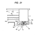
- Fig. 21 a fragmental schematic front view showing a cap close (capping) condition of the cleaning mechanism portion of Fig. 20 .
- a carriage 6 on which a recording head is mounted and which is shifted in a main scan direction relative to a recording medium such as a paper is shifted for shifting and guiding movements by means of guide shafts 101a and 101b provided on a chassis 101.
- a part of a timing belt 103 is connected to the carriage 6, and the carriage 6 is driven along the guide shafts 101a and 101b by transmitting a rotation of a CR (carriage) motor 102 secured to the chassis 101 to the timing belt 103.
- a cleaning mechanism portion 108 is provided, at a base side of a main body of the recording apparatus, at a position facing the recording head mounted on the carriage 6.
- the cleaning mechanism portion 108 is provided with a cap 104 for covering a discharge port face of the recording head.
- the cap 104 is used to prevent solidification of the ink and increase in viscosity of the ink in the vicinity of discharge ports by covering the discharge port face of the recording head in a record waiting condition, and to suck the ink from the discharge ports by generating negative pressure in the cap when processing for recovering clogging of the discharge ports, by connecting the cap 104 to a negative pressure generating source.
- the cap 104 is formed from elastic rubber material or the like.
- the cap 104 is held by a cap holder 105, and the cap holder 105 holding the cap 104 is slidably mounted on a cap slider 106.
- a cap spring 107 is mounted between the cap holder 105 and the cap slider 106.
- a shaft portion 106a provided on the cap slider 106 is supported so as to enable shifting and guiding movements along a cam surface (shown by chain double-dashed line) provided in the base portion of the main body of the recording apparatus. Further, the cap slider 106 is provided with an abutment portion 106b which can abut against a side surface of the carriage 6, and, accordingly, after the carriage 6 enters into the cleaning mechanism portion 108 to abut against the abutment portion 106b, the cap slider 106 can be shifted in synchronous with the shifting movement of the carriage in accordance with the main scan shifting of the carriage 6.
- the cap slider 106 is connected to the main body of the recording apparatus by means of a tension spring 109 so that, when the carriage 6 is not in the cleaning mechanism portion 108, the carriage is held at a predetermined waiting position shown in Fig. 20 by means of the tension spring 109.
- the cleaning mechanism portion 108 having the above-mentioned construction, when the carriage 6 enters into the cleaning mechanism portion 108, the side surface of the carriage 6 abuts against the abutment portion 106b of the cap slider to start the synchronous shifting movement, with the result that the cap slider 106 can similarly be shifted (slid) by the shifting (operation) of the carriage 6.
- the cap slider 106 is gradually lifted toward the recording head by the action of the cam surface (shown by the chain double-dashed line) of the main body of the recording apparatus.
- the cap 104 abuts against the discharge port face of the recording head to establish the capping condition.
- the cap 104 is closely contacted with the discharge port face of the recording head.
- a suction tube 110 is connected to the cap 104 via the cap holder 105 and the other end of the suction tube 110 is connected to the negative pressure generating source (pump portion). Accordingly, in the condition in which the cap 104 is closely contacted with the recording head, by operating the negative pressure generating source, the negative pressure can be created within the cap 104 through the suction tube 110 and the ink can be sucked from the discharge ports of the recording head by the negative pressure.
- Such an ink suction is suction recovery processing for eliminating the clogging of the discharge ports and is one of primary functions of the cleaning mechanism portion 108.
- the cap slider 106 is gradually retarded from the discharge port face of the recording head to establish the cap open condition, with the result that the image can be recorded on the recording medium by the operations of the carriage 6 and the recording head.
- the cleaning operation for the recording head can be performed in accordance with the position of the carriage 6 and the action of the cleaning mechanism portion (pump mechanism portion or the like).
- US 5 733 055 shows a generic ink jet recording apparatus according to the preamble of claim 1 for performing a recording operation by discharging ink from a recording head and a generic cleaning mechanism portion according to the preamble of claim 12 for performing a recording operation by discharging ink from a recording head.
- the generic ink jet recording apparatus comprises a carriage on which the recording head is mounted and which is shifted reciprocally, and a cap for capping an ink discharge portion of the recording head.
- the generic cleaning mechanism portion comprises a cap for capping an ink discharge portion of the recording head.
- EP 0 916 508 A and EP 0 580 437 A show both further ink jet recording apparatuses according to the prior art. These apparatuses have a reciprocally shiftable carriage for carrying a recording head. Further, a capping mechanism for capping ink ejection outlets of the head is shown in EP 0 580 437 A , and a wiping mechanism for cleaning ink ejection outlets in a capping/wiping position of the carriage is shown in EP 0 916 508 A .
- JP 2078561 An apparatus having the features of the preamble of claims 1 and 12 is disclosed in JP 2078561 .
- Fig. 1 is a schematic perspective view showing a first embodiment of an ink jet recording apparatus to which the present invention is applied.
- the illustrated ink jet recording apparatus includes a sheet feeding portion 201 for supplying a recording material such as a recording paper into a main body of the recording apparatus, a conveying portion 202 for conveying the recording material through the main body (recording portion and the like) of the recording apparatus, a recording mechanism portion 203 for recording an image (including a character and/or a symbol) on the recording medium on the basis of image information, and a cleaning mechanism portion (recovering mechanism portion) 204 for maintaining a quality of the image formed by the recording mechanism.
- a sheet feeding portion 201 for supplying a recording material such as a recording paper into a main body of the recording apparatus
- a conveying portion 202 for conveying the recording material through the main body (recording portion and the like) of the recording apparatus
- a recording mechanism portion 203 for recording an image (including a character and/or a symbol) on the
- Recording materials such as recording papers stacked on the sheet feeding portion 201 are separated and fed one by one by means of a sheet feeding roller driven by a sheet feeding motor and the separated recording material is sent to the conveying portion 202.
- the recording material sent to the conveying portion 202 is conveyed through the recording portion by a friction conveying force obtained by a conveying roller 221 driven by a convey motor and a pinch roller 222 urged against the conveying roller, and, in the recording portion, the image (including a character and/or a symbol) is recorded on the recording material by the recording mechanism portion 203 while paper-feeding the recording material (pitch conveyance).
- the recorded recording material is pinched between a sheet discharging roller 223 and a spur roller cooperating with the sheet discharging roller to be conveyed out of the main body of the apparatus.
- the recording mechanism portion 203 comprises a carriage 6 guided and supported for a reciprocal movement in a main scan direction within the main body of the apparatus, and a recording head 3 as recording means. That is to say, the carriage 6 on which the recording head 3 is guided and supported for the reciprocal movement along guide rails provided on the main body of the apparatus, and a driving force of a carriage motor is transmitted to the carriage 6 via a carriage belt 224 so that the carriage 6 is reciprocally shifted along the guide rails by the driving force of the carriage motor.
- the recovering mechanism portion (cleaning mechanism portion) 204 serves to recover and maintain recording quality to a proper (good) condition by eliminating clogging of the recording head (ink jet head) 3 in the ink jet recording apparatus and comprises pump means for sucking or discharging ink from discharge ports, cap means for covering the discharge ports, and wiping means for wiping and cleaning a discharge port face of the recording head, as will be described later.
- the recording head 3 as the recording means is an ink jet recording head for discharging the ink by utilizing thermal energy and includes electrical/thermal converters for generating the thermal energy. Further, the recording head 3 conducts the recording by creating film boiling in the ink by the thermal energy applied from the electrical/thermal converters, and discharging the ink from the discharge ports by utilizing change in pressure due to growth and contraction of bubbles generated by the film boiling.
- the electrical/thermal converters are provided in correspondence to plural discharge ports so that, by applying pulse voltage to the selected electrical/thermal converters in response to recording information (recording signal), the ink is discharged from the corresponding discharge ports.
- Fig. 2 is a partial perspective view schematically showing a structure of an ink discharging portion of the recording head 3.
- a plurality of discharge ports 82 are formed at a predetermined pitch on a discharge port face 81 opposed to the recording medium such as the recording paper with a predetermined gap (for example, about 0.2 mm to about 2.0 mm) therebetween, and electrical/thermal converters (heat generating resistors) 85 for generating ink discharging energy are disposed along wall surfaces of respective liquid paths 84 communicating the respective discharge ports 82 with a common liquid chamber 83.
- the recording head 3 is mounted on the carriage in such a manner that the discharge ports 82 are arranged side by side along a direction intersecting with the main scan direction (shifting direction of the carriage 6). In this way, the recording head for performing the recording operation by discharging the ink from the discharge port 82 by the pressure generated by the film boiling created in the ink within the liquid path 84 by driving (energizing) the electrical/thermal converter 85 in response to an image signal or a discharging signal is constituted.
- Figs. 3A to 3C are explanatory views showing the discharge port face 81 of the recording head according to the illustrated embodiment, where Fig. 3A shows an arrangement of black discharge port array and color discharge port arrays in the discharge port face 81, Fig. 3B is an explanatory view showing a positional relationship between the black and color discharge port arrays and a suction port (described later) of the cap (the cap one end open side as well), and Fig. 3C is an explanatory view showing another arrangement example (positional relationship) between the black and color discharge port arrays and the suction port (described later) of the cap.
- Fig. 4 is a perspective view of the recording head 3, looked at from the discharge port face side, and Fig.
- FIG. 5 is a front view of the recording head 3, looked at from the discharge port face side.
- color (for example, cyan, magenta and yellow) discharge port arrays 3c and a black discharge port array 3d are formed in the discharge port face 81 of the recording head 3 according to the illustrated embodiment.
- the recording operation is conducted in such a manner that the ink discharging is firstly performed by using the discharge port at the sheet feeding side (upstream side) of the black discharge port array, the recording material (paper) is conveyed by a predetermined amount up to a location where the recording is to be performed by using the color discharge port, and then color ink is discharged from the color discharge port, thereby avoiding the above-mentioned problem.
- the recording speed can be increased.
- Fig. 6 is a top perspective view of a cap and a cap holder of the cleaning mechanism portion (recovering mechanism portion) 204 in the first embodiment.
- Fig. 7 is a bottom perspective view of the cap and the cap holder of Fig. 6 .
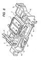
- Fig. 8 is a top perspective view showing a construction on a cap slider of the cleaning mechanism portion 204 in the first embodiment.
- Fig. 9 is a bottom perspective view showing the construction on the cap slider, with a lock lever omitted.
- Fig. 10 is a top perspective view showing a capping position of the entire construction of the cleaning mechanism portion 204 in the first embodiment.
- Fig. 11 is a top perspective view showing a condition at a cap open position of the cleaning mechanism portion 204 of Fig. 10 .
- Fig. 12 is a top perspective view showing a construction of a base portion of the main body of the recording apparatus in the cleaning mechanism portion of Fig. 10 .
- a cap 1 is positioned and secured with respect to a cap holder 2 by four fitting portions 1a and sealing portions of suction ports 1b and 1c within a cap chamber.
- the cap holder 2 is attached to a cap slider 7 by four hook portions (pawl portions) 2b to prevent the cap holder from dislodging upwardly and downwardly.
- a cap spring 4 for biasing the cap holder upwardly is mounted between the cap holder 2 and the cap slider 7.
- shaft portions 2c provided on both ends (in the carriage shifting direction) of the cap holder 2 are fitted into groove portions of the cap slider 7 so that the cap holder 2 is rotatably mounted to the cap slider 7 for a rotational movement around the shaft portions 2c in a front-and-rear direction (direction transverse to the shifting direction of the carriage 6).
- positions of the suction ports 1b and 1c of the cap 1 and the cap holder 2 are selected to be positioned within a range opposed to the color discharge port arrays 3c if positions of the color discharge port arrays 3c of the recording head 3 are offset toward one side (toward a downstream side in the recording material conveying direction in the illustrated example) with respect to the cap 1.
- the cap holder 2 when the cap holder 2 is positioned and mounted at a predetermined position on the cap slider 7, the cap holder 2 can be rotated around the shaft portions 2c in the front-and-rear direction (direction transverse to the shifting direction of the carriage) and further can be position-corrected automatically so that a cap face (seal face) of the cap 1 abut against the discharge port face 81 of the recording head 3 in parallel with each other when the cap slider is lifted at a capping position (position where the recording head 3 is opposed to the cap 1). Namely, the entire cap face is closely contacted with the discharge port face 81 automatically and uniformly, thereby achieving a positive sealing function.
- cap holder 2 is provided with a cap open cam surface 2d having two surfaces (oblique surfaces), that is, an oblique surface and a horizontal surface, formed along the shifting direction of the carriage at a position in a direction transverse to a line connecting between the two shaft portions 2c.
- tubes 5, 5 are connected to positions corresponding to the suction ports 1b and 1c of the cap holder 2 and these tubes are connected to a pump mechanism portion (not shown) as negative pressure generating means. Accordingly, in a condition that the recording head 3 is capped by the cap 1, by activating the pump mechanism portion, a negative pressure condition is created within the cap 1 via the tubes 5, 5, with the result that the ink can be sucked (drawn out) from the discharge ports of the recording head 3.
- the cap 1 has a divided structure in which the interior of the cap is partitioned into two compartments so that inks from the color discharge port arrays 3c and the black discharge port array 3d of the recording head 3 can be sucked independently
- a structure having no partition or a divided structure having three or more compartments can be used, in dependence upon the an arrangement of discharge port arrays of the recording head 3 and/or a sucking method, and, in such a case, similar operation and function can be achieved.
- the cap slider 7 holding the cap holder 2 is connected (joined) to the base portion 13 of the main body of the recording apparatus via a slider spring 15. Further, four rod-shaped protruded portions (slider shaft portions) 7b are provided on side surfaces of the cap slider 7 and these protruded portions 7b are rested on (abut against) slider controlling cam surfaces 13b and 13c provided on the base portion 13. Namely, the cap slider 7 is so mounted as to enable a shifting movement in the carriage shifting direction along the cam surfaces 13b and 13c while controlling a vertical position of the cap slider in a condition that the respective protruded portions (slider shaft portions) 7b are urged against the cam surfaces 13b and 13c of the base portion 13 by the slider spring 15.
- cam portions both of or any one of members (portions) constituting the cam mechanism are referred to as “cam portions” or “cam surfaces.”
- tip ends of several portions are provided with recessed portions (groove portions) for positioning the cap slider 7 by pinching a rib portion forming the cam surface 13c of the base portion therebetween.
- the cap slider 7 is provided with an abutment portion 7a against which the carriage 6 or the recording head 3 entering into the cleaning mechanism portion 204 abuts. Namely, when the carriage 6 is shifted into the cleaning mechanism portion 204 to abut the side surface of the carriage 6 against the abutment portion 7a, the slider 7 is also shifted in accordance with the entering of the carriage 6 into the cleaning mechanism portion.
- the base portion 13 is provided with a fixed cam portion 13a adapted to open one end of the cap 1 and horizontally extending toward the cap holder 2.
- the cam portion 13a serves to open one end of the cap 1 (end at a downstream side in the recording material conveying direction in the illustrated embodiment) in the capping condition by abutting against a cap open cam surface 2d of the cap holder 2.
- Wiper blades 8 and 9 for wiping and removing foreign matters such as residual ink remaining on the discharge port face 81 of the recording head 3 are attached to the end of the cap slider 7.
- These wiper blades 8 and 9 are attached to the cap slider 7 via a blade spacer 10 and are held at predetermined positions on the cap slider 7 by a metal plate blade stopper 11 having a spring property.
- cap slider 7 is provided with a fitting pin 7c to be fitted into (or engaged with) a fitting hole (groove) 3a ( Figs. 4 and 5 ) formed in the recording head 3 or the carriage 6 with a predetermined gap L1 (refer to Fig. 14 ) therebetween.
- Fig. 13 is a schematic front view showing a condition that the carriage and the recording head approach the cleaning mechanism portion but do not yet abut against the cap slider.
- Fig. 14 is a schematic front view showing a capping condition in which the carriage and the recording head enter into the cleaning mechanism portion and shift the cap slider accordingly to thereby closely contact the cap with the discharge port face.
- Fig. 15 is a schematic front view showing a cap one end open condition in which one end of the cap is opened when the carriage and the recording head further advance in the entering direction in the capping condition.
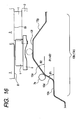
- Fig. 16 is a schematic view for explaining the cam surface of the base portion and a function of the cam surface for controlling the position of the cap slider of the cleaning mechanism portion.
- Fig. 17 is a schematic side view showing the cap one end open condition of Fig. 15 .
- Fig. 18 is a schematic front view showing an operating condition of a lock lever provided on the cap slider so as to enable a sliding movement in the carriage shifting direction.
- the carriage 6 and the recording head 3 are situated in positions (as shown in Fig. 13 ) where the carriage and the recording head do not yet enter into the cleaning mechanism portion, the carriage 6 and the recording head 3 are spaced apart from the wiper blades 8 and 9 with a predetermined clearance in the vertical direction, and, thus, the carriage and the recording head do not abut against the wiper blades.
- the capping condition of the recording head 3 condition in which the discharge port face 81 is covered by the cap 1 as shown in Fig. 14 is achieved by lifting the cap slider 7 by means of the carriage 6 entering into the cleaning mechanism portion, the wiper blade 9 is positioned with a predetermined clearance L2 with respect to the carriage 6, and, thus, in the capping condition, the carriage does not contact the blades 8 and 9.
- the distance (gap) L1 is selected to be smaller than the gap L2 between the carriage 6 and the blade 9 so that the carriage 6 does not contact the wiper blades 8 and 9 even if the fitting pin 7c is in contact with the recording head 3 due to deviation between the fitting pin and the recording head in the main scan direction.
- the fitting hole into which the fitting pin 7c is fitted with the predetermined gap may be provided in the carriage 6.
- a lock lever 12 slidably engaged with one of the four protruded portions (slider shaft portions) 7b is mounted to the cap slider 7.
- an end 12a of the lock lever 12 is connected (joined) to the base portion 13 of the recording apparatus via a lock lever spring 14.
- the base portion 13 of the recording apparatus is provided with a cam portion 13j for the lock lever 12. The cam portion 13j can abut against (engage with) a cam surface 12b of the lock lever 12. In this way, the lock lever 12 is held to be pinched between the cap slider 7 and the base portion 13 of the recording apparatus. A detailed operation of the lock lever 12 will be described later.
- portions (members) abutting against or engaging with opposite members by utilizing the shifting movement and/or position of the carriage may be freely provided or formed on one or both of the parts such as the carriage and the recording head mounted to the carriage.
- the present invention is not limited to the illustrated construction in which the members are provided on either one of the parts. Accordingly, if it is not defined specially, even when a case where the members are provided on either one of the parts is disclosed (described), the present invention may include a case where the members are provided on both of the parts.
- Fig. 13 when the carriage 6 enters into the cleaning mechanism portion 204 to perform the cleaning operation for the recording head 3, from a position where the side surface of the carriage 6 starts to abut against the abutment portion 7a of the cap slider 7, the cap slider 7 starts to be shifted in the main scan direction in accordance with the movement of the carriage 6.
- the shifting movement of the cap slider 7 is started, the entire cap slider is shifted along the cap slider controlling cam surfaces 13b and 13c while being pushed to the right in Fig. 13 and is also shifted gradually toward the recording head 3.
- the cap slider 7 When the cap slider 7 is shifted upwardly, the distance between the cap 1 and the recording head 3 is gradually decreased and, ultimately, the end face (cap face) of the cap 1 abuts against the discharge port face 81. Since the cap holder 2 holding the cap 1 is connected (joined) to the cap slider 7 via the cap spring 4, after the cap 1 abuts against the discharge port face 81 of the recording head, the cap holder 2 is pushed down (or shifted down) relative to the cap slider 7, opposing the cap spring 4 to be housed into the cap slider 7. At the same time, the urging force of the cap spring 4 is gradually increased and the cap 1 is closely in contact with the recording head 3, thereby establishing the capping condition.
- the cap holder 2 is mounted to the cap slider 7 so as to enable the rotational movement around the shaft portions 2c, the entire surface of the cap 1 is closely in contact with the discharge port face 81 uniformly while automatically correcting (equalizing) an abutment angle so that the cap is in contact with the discharge port face 81 of the recording head 3 horizontally (in parallel).
- Fig. 14 when the carriage 6 is shifted up to a position where the carriage ascends on the top of the cam surfaces 13b and 13c of the base portion 13 of the recording apparatus, a portion of the discharge port face 81 of the recording head 3 including the discharge port arrays is completely capped. In this capping condition, when the negative pressure is generated within the cap 1 by activating the negative pressure generating means (pump mechanism portion) connected to the tubes 5, 5, the ink can be sucked from the discharge ports 82 of the recording head 3.
- the configurations of the cam surfaces 13b and 13c which extend up to a position where the cap 1 abuts against the recording head 3 are formed as steep oblique surfaces and configurations of the cam surfaces 13b and 13c which extend from the position where the cap 1 abuts against the recording head 3 to the capping position are formed as gentle oblique surfaces. That is to say, as shown in Fig.
- the inclined angle of the cam surface 13b or 13c of the base portion 13 is selected so that an angle ⁇ 1 of an oblique surface 13d extending up to the cap abutting position becomes greater than an angle ⁇ 2 of an oblique surface 13e extending from the cap abutting position to the capping position.
- the reference numeral 13f in Fig. 16 indicates a top of the oblique surfaces of the cam portion 13b or 13c, and, when the carriage 6 ascends up to this cam position 13f, the capping condition in which the cap 1 is closely in contact with the recording head 3 completely is established. In this capping position 13f, it is designed so that the spring pressure of the cap spring 4 acts on the recording head 3 by a required amount.
- the cap holder 2 is rotated around the shaft portions 2c to open a front side (downstream side in the recording material conveying direction) one end of the cap 1, and, when the carriage 6 is shifted up to the cap one end open position shown in Fig. 15 , the gap (open amount) between the cap and the discharge port face 81 of the recording head 3 can be kept constant at one end of the cap 1 by a horizontal portion of the cap open cam surface 2d of the cap holder 2.
- an opposite oblique surface 13g is formed on the cam surface 13b (13d) of the base portion 13 within a range in which the carriage 6 is shifted from the capping position ( Fig.
- the opposite oblique surface 13g serves to reduce the sliding load of the carriage 6 by escaping (or reducing) an abutment force between the cap 1 and the discharge port face 81 generated by the cap spring 4 within the range where the carriage 6 is shifted from the capping position ( Fig. 14 ) to the cap one end open position ( Fig. 15 ).
- the ink remaining on the discharge port face 81 is dispersed on the entire discharge port face 81 upon opening of the cap, so that, even when the pump mechanism portion as the negative pressure generating means connected to the cap is activated in the condition in which the cap 1 is opened, the ink remaining on the discharge port face 81 can almost not removed, with the result that color mixing will occur by the fact that the ink remaining around the discharge ports adhere to the adjacent different color ink.
- the end sides of the discharge port arrays 3c and 3d of the recording head 3 in the capping condition i.e., ends at the downstream side (at the front side of the main body) in the recording material conveying direction are opened.
- the ink flows can be directed along the discharge port arrays 3c and 3d.
- the ink within the cap 1 can be fully sucked until the recording head 3 and the cap 1 are separated, thereby effectively removing the residual ink remaining on the discharge port face 81 of the recording head 3.
- the residual ink can be removed more effectively (in a good manner) in comparison with the conventional arrangement in which the cap 1 is opened in parallel with the recording head 3.
- the suction port 1b is provided at the position opposed to the discharge ports.
- the ink can be removed from the discharge port face 81 of the recording head 3 more effectively by providing the suction port in the cap 1 at a downstream side in the recording material conveying direction.
- the cap slider 7 When the carriage 6 is shifted in the retard direction, the cap slider 7 is naturally shifted (follows) on the cam surfaces 13b and 13c in a direction opposite to the direction along which the carriage 6 advances. According to the construction of the illustrated embodiment, when the carriage is shifted away from the cleaning mechanism portion, even if the spring force of the cap slider spring 15 cannot suddenly be maintained adequately due to occurrence of the above-mentioned inconvenience, since the fitting pin 7c provided on the cap slider 7 is fitted into the fitting hole 3a of the recording head 3, the cap slider 7 can be shifted in synchronous with the carriage 6 and, thus, the cap slider 7 can be shifted in the retard direction to follow the carriage 6 positively.
- the cap slider 7 When the carriage 6 is further shifted in the retard direction, the cap slider 7 is lowered in accordance with the shapes of the cam surfaces 13b and 13c, with the result that the fitting pin 7c is disengaged from the fitting hole 3a of the recording head 3. Since the lock lever 12 is held not to be shifted from the lock position engaged by the cam portion 13j and the slider shaft portions 7b are held by the lock lever 12 at the position of the cam surface 13h, the cap slider 7 is separated from the carriage 6.
- the cam surface 13h is constituted by a horizontal surface in order to stably maintain the vertical gap between the discharge port face 81 of the recording head 3 and the cap 1 and penetrating amounts of the wiper blades 8 and 9 onto the discharge port face 81 when the cap slider 7 is held by the lock lever 12.
- the recording head 3 mounted on the carriage 6 passes through the wiper blades 8 and 9, with the result that, as shown in Fig. 18 , the discharge port face 81 of the recording head 3 is wiped (cleaned) by the wiper blades 8 and 9, thereby further removing the residual ink around the discharge port arrays 3c and 3d after the suction processing.
- the lock lever releasing protruded portion 6a provided on the carriage 6 urges the tip end portion 12c of the lock lever 12, with the result that the lock lever 12 is rotated in an anti-clockwise direction in Fig. 18 around the protruded portions (slider shaft portions) 7b of the cap slider 7, thereby releasing the lock between the cam surface 12b and the horizontal surface of the cam portion 13j.
- the cap slider 7 can be shifted up to a position where the cap 1 is completely retarded from the recording head 3 (original position before the carriage 6 enter into the cleaning mechanism portion 204).
- the ink remaining on the discharge port face during the recording head cleaning operation can effectively be removed with a simple construction.
- the ink jet recording apparatus having the cleaning mechanism portion which can obtain good recording image quality without ink mixing.
- the ink jet recording apparatus having the cleaning mechanism portion in which the cost can be reduced due to the compactness of the carriage motor and the main body of the recording apparatus can be made compact.
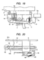
- Fig. 19 is a side view, partially in section, schematically showing a main construction of a second embodiment of a cleaning mechanism portion of an ink jet recording apparatus to which the present invention is applied.
- a second embodiment explained in connection with Fig. 1 to Fig. 18
- the cleaning mechanism portion in which the residual ink remaining on the discharge port face 81 of the recording head is removed by opening the one end of the cap is explained
- an open/close valve for communicating the interior of the cap with atmosphere is adopted.
- the same or corresponding parts or elements as those in the first embodiment are designated by the same reference numerals.
- FIG. 19 shows a construction of a cap holder 16 of a cleaning mechanism portion according to the second embodiment and its vicinity, which can eliminate such inconvenience.
- an ink jet recording apparatus having the cleaning mechanism portion shown in Fig. 19 substantially includes the same construction as that in the first embodiment explained in connection with Fig. 1 to Fig. 18 , so long as it is not specially defined.
- a cap 18 and the cap holder 16 are provided with atmosphere communication through-holes 18a, as well as the suction ports for ink suction. Further, each suction port of the cap 18 or the cap holder 16 is connected to a suction tube 5 similar to that in the first embodiment, thereby constituting the similar ink suction mechanism.
- An atmosphere communicating valve opening/closing member (rocking member, movable member) 17 suspended by a spring 19 is rockably supported at a rear surface side of the cap holder 16 so as to enable a rocking movement.
- the movable member 17 is provided at its tip end with a valve opening cam surface 17a similar to the cap open cam surface 2d in Fig. 6 .
- An opening/closing valve (atmosphere communicating valve) 20 for opening and closing the atmosphere communicating through-holes 18a is secured to a predetermined part of the movable member (rocking member, atmosphere communicating valve opening/closing member) 17.
- the reference numeral 13a in Fig. 19 denotes a cam portion similar to the fixed cam portion 13a shown in Figs. 7 , 8 , 14 and 15 , i.e., the fixed cam portion provided at a predetermined position on the main body of the recording apparatus.
- the residual ink after the suction recovery can be removed by opening and closing the atmosphere communicating valve 20 in the condition in which the cap 18 is closely in contact with the discharge port face 81 of the recording head 3. Accordingly, similar to the first embodiment, with a simple construction including a fewer number of parts, the ink remaining on the discharge port face during the recording head cleaning operation can be removed effectively.
- the ink jet recording apparatus having the cleaning mechanism portion, which can obtain a good recording image quality without ink color mixing.
- the present invention can be carried out without limiting the present invention to the number of the recording heads and the number of the discharge port arrays explained in the above-mentioned embodiments. Further, the present invention can be carried out without limiting the present invention to the kind and the number of inks used and, thus it can be applied to, for example, a color ink jet recording apparatus for performing the recording by using plural different color inks, a gradation recording ink jet recording apparatus in which an image is recorded with the same color having plural different densities or an ink jet recording apparatus obtained by combining the aforementioned recording apparatuses.
- the present invention can similarly be applied to various constructions having different arrangement relationship between the recording head and an ink tank, such as a construction utilizing an exchangeable ink jet cartridge in which an ink tank is integrally formed with a recording head, a construction utilizing recording means in which an ink tank is detachably mounted to a recording head or a construction in which a recording head and an ink tank are formed separately and they are interconnected via an ink supply path.
- the present invention can similarly be applied to, for example, an ink jet recording apparatus utilizing a recording head driven by other operating system, such as a recording head using an electrical/mechanical converter such as a piezoelectric element.
- the same effect can be achieved.
- excellent effect can be achieved in an ink jet recording apparatus using a recording head of type in which ink is discharged by utilizing thermal energy. According to such a type, high density recording and highly fine recording can be achieved.
- an ink jet recording apparatus for recording an image on a recording material by using a recording head mounted on a carriage shifted reciprocally, there is provided a cleaning mechanism for performing a capping operation by closely contacting a cap with the recording head by shifting a cap slider on which the cap for capping a discharge port portion of the recording head along a cam surface provided on a main body of the recording apparatus by utilizing a shifting movement of the carriage, and since the cleaning mechanism portion has cap one end open means in which, after the carriage enters into the cleaning mechanism portion and the recording head is capped by the cap, one end of the cap is opened by further shifting the carriage in an advancing direction in a capping condition, an ink jet recording apparatus having a cleaning mechanism portion, which can maintain stable recording quality by adequately removing ink remaining on the discharge port face during cleaning processing of the recording head is provided.
- the present invention provides an ink jet recording apparatus which can maintain stable recording quality by adequately removing ink remaining on discharge ports during cleaning processing of a recording head, and a cleaning mechanism portion for such a recording apparatus.
- an ink jet recording apparatus in which, after a carriage enters into a cleaning mechanism portion and a recording head is capped by a cap, when the carriage is further shifted in an advancing direction in a capping condition, one end of the cap is opened.
Landscapes
- Ink Jet (AREA)
Claims (12)
- Tintenstrahlaufzeichnungsgerät zum Ausführen eines Aufzeichnungsvorgangs durch Ausstoßen von Tinte aus einem Aufzeichnungskopf (3), mit:einem Schlitten (6), auf dem der Aufzeichnungskopf (3) montiert ist und der hin- und herverschiebbar ist; undeiner Abdeckung (1) zum Abdecken eines Tintenausstoßabschnitts (81) des Aufzeichnungskopfs (3);einem Reinigungsmechanismusabschnitt (204), der einen Abdeckvorgang durch Verschieben eines Abdeckungsschiebers (7), der die Abdeckung (1) hält, entlang einer Nockenfläche (13b, 13c) durch Ausnutzen der Verschiebungsbewegung des Schlittens (6) ausführt, wobei die Nockenfläche derart ist, dass, nachdem der Schlitten (6) in den Reinigungsmechanismusabschnitt (204) in einer Vorrückrichtung eintritt, der Aufzeichnungskopf (3) durch die Abdeckung (1) abgedeckt wird; und dadurch gekennzeichnet ist, dass, wenn der Schlitten (6) in einem Abdeckungszustand weiter in die Vorrückrichtung verschoben wird, ein Ende der Abdeckung (1) geöffnet wird.
- Tintenstrahlaufzeichnungsgerät nach Anspruch 1, wobei eine Abdeckungshalterung (2), die die Abdeckung (1) hält, über Wellenabschnitte (2c), die an beiden Enden der Abdeckungshalterung (2) vorgesehen sind, drehbar an dem Abdeckungsschieber (7) angeordnet ist, und ein Abdeckungsöffnungsnocken (2d) an einem Teil vorgesehen ist, der von den Wellenabschnitten (2c) der Abdeckungshalterung (2) in einer Richtung quer zu der Achse der Wellenabschnitte (2c) entfernt angeordnet ist, so dass, wenn der Schlitten (6) verschoben wird, um den Abdeckungsöffnungsnocken (2d) gegen einen ortsfesten Nocken (13a) zu stoßen, der an einem Hauptkörper des Aufzeichnungsgeräts vorgesehen ist, ein Anstoßwinkel der Abdeckung relativ zu dem Aufzeichnungskopf (3) verändert wird.
- Tintenstrahlaufzeichnungsgerät nach Anspruch 2, wobei der Abdeckungsöffnungsnocken (2d) eine schräge Fläche zum Öffnen eines Endes der Abdeckung (1) durch die Verschiebungsbewegung des Schlittens (6) und eine parallele Fläche zum konstanten Halten eines Öffnungsausmaßes der Abdeckung (1) aufweist.
- Tintenstrahlaufzeichnungsgerät nach Anspruch 1, wobei der Aufzeichnungskopf (3) eine Vielzahl von unterschiedlichen Farbausstoßanschlussreihen (3c, 3d) hat, und ein Endabschnitt der Abdeckung (1) nahe den Ausstoßanschlussreihen (3c, 3d) geöffnet wird.
- Tintenstrahlaufzeichnungsgerät nach Anspruch 4, wobei, wenn die Vielzahl von unterschiedlichen Farbausstoßanschlussreihen (3c, 3d) versetzt von einer mittleren Position der Abdeckung (1) in einer Förderichtung eines Aufzeichnungsmaterials angeordnet sind, ein Tintensauganschluss (1b; 1c) der Abdeckung (1) an einer Position vorgesehen ist, die mit den Ausstoßanschlussreihen (3c, 3d) in der Förderrichtung des Aufzeichungsmaterials überlappt.
- Tintenstrahlaufzeichnungsgerät nach Anspruch 5, wobei eine Förderfläche des Aufzeichungsmaterials in Bezug auf eine Installationsfläche des Aufzeichnungsgeräts schräg angeordnet ist, so dass eine Blattabgabeseite der Förderfläche niedriger als eine Blattzufuhrseite der Förderfläche ist, und die Vielzahl von Ausstoßanschlussreihen (3c, 3d) parallel entlang einer Richtung quer zu der Förderrichtung des Aufzeichungsmaterials sind, und der Tintensauganschluss (1b; 1c) der Abdeckung (1) in der Blattabgabeseite an einer Position vorgesehen ist, die mit den Ausstoßanschlussreihen (3c, 3d) überlappt, und das Ende der Abdeckung (1) nahe den Ausstoßanschlussreihen (3c, 3d) geöffnet wird.
- Tintenstrahlaufzeichnungsgerät nach Anspruch 1, wobei das Innere der Abdeckung (1) mit einer Unterdruckerzeugungseinrichtung verbunden ist, so dass, nachdem ein Unterdruck innerhalb der Abdeckung (1) durch die Unterdruckerzeugungseinrichtung erzeugt worden ist, um Tinte in einem Zustand anzusaugen, in dem Ausstoßanschlüsse (82) des Aufzeichnungskopfs (3) durch die Abdeckung (1) dicht abgedichtet sind, ein Ende der Abdeckung (1) durch Weiterschieben des Schlittens (6) in die Vorrückrichtung geöffnet wird, während die Unterdruckerzeugungseinrichtung in Betrieb ist.
- Tintenstrahlaufzeichnungsgerät nach Anspruch 1, wobei der Abdeckungsschieber (7) mit einem Befestigungsstift (7c) zum Befestigen in einem Befestigungsloch (3a) des Aufzeichnungskopfs (3) mit einem vorbestimmten Abstand dazwischen innerhalb eines Verschiebebereichs des Schlittens (6) vorgesehen ist, in dem von einer Abdeckungsposition weiter vorgerückt wird, in der die Abdeckung (1) gegen den Aufzeichnungskopf (3) stößt.
- Tintenstrahlaufzeichnungsgerät nach Anspruch 2, wobei bei dem ortsfesten Nocken (13a) ein Winkel seiner schrägen Nockenfläche, bevor die Abdeckung (1) gegen den Aufzeichnungskopf (3) stößt, von einem Winkel seiner schrägen Nockenfläche, nachdem die Abdeckung (1) gegen den Aufzeichnungskopf (3) stößt, verschieden ist.
- Tintenstrahlaufzeichnungsgerät nach Anspruch 9, wobei der ortsfeste Nocken (13a) eine schräge Nockenfläche, die mit einem entgegengesetzten Winkel gegenüberliegend zu der schrägen Nockenfläche ausgebildet ist, bis der Schlitten (6) eine Abdeckungsposition erreicht und innerhalb eines Bereichs aufweist, in dem der Schlitten (6) von der Abdeckungsposition zu einer Position verschoben wird, in der ein Ende der Abdeckung (1) geöffnet ist.
- Tintenstrahlaufzeichnungsgerät nach Anspruch 9, wobei ein Positionieren des Abdeckungsschieber (7) in Bezug auf den Hauptkörper des Aufzeichnungsgeräts durch Eingreifen der Nockenfläche (13b, 13c), die an dem Hauptkörper des Aufzeichnungsgeräts zum Führen einer Verschiebungsbewegung des Abdeckungsschiebers (7) vorgesehen ist, mit einem ausgesparten Abschnitt ausgeführt wird, der in einem vorderen Ende des Abdeckungsschiebers (7) vorgesehen ist.
- Reinigungsmechanismus für ein Tintenstrahlaufzeichnungsgerät zum Ausführen eines Aufzeichnungsvorgangs durch Ausstoßen von Tinte aus einem Aufzeichnungskopf (3), mit:einer Abdeckung (1) zum Abdecken eines Tintenausstoßabschnitts (81) des Aufzeichnungskopfs (3);einem Reinigungsmechanismusabschnitt (204), der einen Abdeckvorgang durch Verschieben eines Abdeckungsschiebers (7), der die Abdeckung (1) hält, entlang einer Nockenfläche (13b, 13c) durch Ausnutzen einer Verschiebungsbewegung eines Schlittens (6) ausführt, auf dem ein Aufzeichnungskopf (3) montiert ist, wobei die Nockenfläche derart ist, dass, nachdem der Schlitten (6) in den Reinigungsmechanismusabschnitt (204) eintritt, der Aufzeichnungskopf (3) durch die Abdeckung (1) abgedeckt wird; und dadurch gekennzeichnet ist, dass, wenn der Schlitten (6) in einem Abdeckungszustand weiter in eine Vorrückrichtung verschoben wird, ein Ende der Abdeckung (1) geöffnet wird.
Applications Claiming Priority (2)
| Application Number | Priority Date | Filing Date | Title |
|---|---|---|---|
| JP2002166931 | 2002-06-07 | ||
| JP2002166931A JP3827302B2 (ja) | 2002-06-07 | 2002-06-07 | インクジェット記録装置 |
Publications (3)
| Publication Number | Publication Date |
|---|---|
| EP1369242A2 EP1369242A2 (de) | 2003-12-10 |
| EP1369242A3 EP1369242A3 (de) | 2006-10-25 |
| EP1369242B1 true EP1369242B1 (de) | 2009-08-19 |
Family
ID=29545877
Family Applications (1)
| Application Number | Title | Priority Date | Filing Date |
|---|---|---|---|
| EP03012791A Expired - Lifetime EP1369242B1 (de) | 2002-06-07 | 2003-06-05 | Farbstrahlaufzeichnungsgerät und Reinigungsteil |
Country Status (5)
| Country | Link |
|---|---|
| US (1) | US6913340B2 (de) |
| EP (1) | EP1369242B1 (de) |
| JP (1) | JP3827302B2 (de) |
| CN (1) | CN1302932C (de) |
| DE (1) | DE60328850D1 (de) |
Families Citing this family (43)
| Publication number | Priority date | Publication date | Assignee | Title |
|---|---|---|---|---|
| JP2004092431A (ja) * | 2002-08-29 | 2004-03-25 | Toyota Motor Corp | 排気ガス浄化装置 |
| JP2005254771A (ja) * | 2004-03-15 | 2005-09-22 | Sharp Corp | インクジェットプリンタのメンテナンス機構 |
| US7703880B2 (en) * | 2004-05-18 | 2010-04-27 | Canon Kabushiki Kaisha | Inkjet recording apparatus |
| JP4695854B2 (ja) * | 2004-06-14 | 2011-06-08 | キヤノン株式会社 | インクジェット記録装置 |
| JP2006188312A (ja) * | 2005-01-04 | 2006-07-20 | Funai Electric Co Ltd | プリンタ |
| JP4920903B2 (ja) * | 2005-05-12 | 2012-04-18 | キヤノン株式会社 | インクジェット記録装置 |
| JP4819394B2 (ja) * | 2005-05-12 | 2011-11-24 | キヤノン株式会社 | 記録ヘッドの吸引方法 |
| CN100393520C (zh) * | 2005-05-13 | 2008-06-11 | 明基电通股份有限公司 | 可控制遮盖墨盒的喷墨孔的位置的打印机 |
| US7401888B2 (en) * | 2005-10-11 | 2008-07-22 | Silverbrook Research Pty Ltd | Method of maintaining a printhead using maintenance station configured for air blast cleaning |
| US7401887B2 (en) * | 2005-10-11 | 2008-07-22 | Silverbrook Research Pty Ltd | Method of maintaining a printhead using air blast cleaning |
| US7387358B2 (en) * | 2005-10-11 | 2008-06-17 | Silverbrook Research Pty Ltd | Printhead maintenance assembly configured for air blast cleaning |
| JP4793555B2 (ja) * | 2005-10-18 | 2011-10-12 | ブラザー工業株式会社 | 画像記録装置 |
| JP2007190849A (ja) * | 2006-01-20 | 2007-08-02 | Seiko Precision Inc | プリンタ及び印刷ヘッド装置 |
| JP5317396B2 (ja) * | 2006-07-03 | 2013-10-16 | キヤノン株式会社 | インクジェット記録装置 |
| JP4958533B2 (ja) * | 2006-12-19 | 2012-06-20 | キヤノン株式会社 | インクジェット記録装置 |
| JP2008162064A (ja) * | 2006-12-27 | 2008-07-17 | Seiko Epson Corp | キャッピング操作機構、メンテナンスユニット、及び液体噴射装置 |
| JP4831347B2 (ja) * | 2007-01-12 | 2011-12-07 | セイコーエプソン株式会社 | キャッピング操作機構、メンテナンスユニット、及び液体噴射装置 |
| JP5127561B2 (ja) * | 2007-07-11 | 2013-01-23 | キヤノン株式会社 | インクジェット記録装置 |
| JP5183121B2 (ja) * | 2007-08-10 | 2013-04-17 | キヤノン株式会社 | インクジェット記録装置 |
| JP2009297989A (ja) * | 2008-06-12 | 2009-12-24 | Canon Inc | インクジェット記録装置 |
| JP5274115B2 (ja) * | 2008-06-12 | 2013-08-28 | キヤノン株式会社 | インクジェット記録装置及びその制御方法 |
| JP5441494B2 (ja) * | 2008-08-07 | 2014-03-12 | キヤノン株式会社 | インクジェット記録装置 |
| US8376509B2 (en) * | 2009-07-31 | 2013-02-19 | Hewlett-Packard Development Company, L.P. | Apparatus for wiping |
| DE112010005417T5 (de) * | 2010-04-30 | 2013-01-03 | Hewlett-Packard Development Company, L.P. | Abdeckung für Tintenstrahldrucker |
| JP5348508B2 (ja) | 2010-06-17 | 2013-11-20 | ブラザー工業株式会社 | インク吐出装置 |
| US8540341B2 (en) * | 2011-03-02 | 2013-09-24 | Seiko Epson Corporation | Maintenance device, power transmission switching device, and liquid ejecting apparatus |
| WO2012134480A1 (en) * | 2011-03-31 | 2012-10-04 | Hewlett-Packard Development Company, L.P. | Printhead assembly |
| JP5853480B2 (ja) * | 2011-08-05 | 2016-02-09 | ブラザー工業株式会社 | 液体噴射装置 |
| JP6099899B2 (ja) * | 2012-07-31 | 2017-03-22 | キヤノン株式会社 | プリント装置および検査方法 |
| JP6341803B2 (ja) * | 2013-12-20 | 2018-06-13 | キヤノン株式会社 | 液体吐出ヘッドの回復方法 |
| JP6365819B2 (ja) * | 2014-02-28 | 2018-08-01 | セイコーエプソン株式会社 | 液体噴射装置 |
| JP2016030382A (ja) * | 2014-07-29 | 2016-03-07 | ブラザー工業株式会社 | 印刷装置 |
| JP6838333B2 (ja) * | 2016-09-23 | 2021-03-03 | ブラザー工業株式会社 | 液体吐出装置 |
| CN108724731B (zh) * | 2017-04-21 | 2020-06-09 | 三纬国际立体列印科技股份有限公司 | 喷头清洁模组 |
| JP7013160B2 (ja) * | 2017-07-28 | 2022-01-31 | キヤノン株式会社 | インクジェット記録装置 |
| JP6437687B1 (ja) * | 2017-08-02 | 2018-12-12 | ローランドディー.ジー.株式会社 | インクジェットプリンタ |
| US10800174B2 (en) | 2019-02-11 | 2020-10-13 | Xerox Corporation | Evaporative ink-blocking film devices stabilizing ink in nozzles of inkjet printheads |
| US10710371B1 (en) * | 2019-02-11 | 2020-07-14 | Xerox Corporation | Inkjet printhead cap having latching system |
| US10894411B2 (en) | 2019-02-11 | 2021-01-19 | Xerox Corporation | Cap and application devices stabilizing ink in nozzles of inkjet printheads |
| US10814631B2 (en) | 2019-02-11 | 2020-10-27 | Xerox Corporation | Inkjet printhead cap having rotatable panels |
| US10857798B2 (en) | 2019-02-11 | 2020-12-08 | Xerox Corporation | Cap and evaporative devices stabilizing ink in nozzles of inkjet printheads |
| US10696052B1 (en) | 2019-02-11 | 2020-06-30 | Xerox Corporation | Submersion cap devices stabilizing ink in nozzles of inkjet printheads |
| US11167575B2 (en) * | 2019-02-27 | 2021-11-09 | Seiko Epson Corporation | Recording apparatus |
Family Cites Families (12)
| Publication number | Priority date | Publication date | Assignee | Title |
|---|---|---|---|---|
| JPH02167752A (ja) | 1988-12-21 | 1990-06-28 | Canon Inc | インクジェット記録装置 |
| DE69222994T2 (de) | 1991-07-31 | 1998-04-02 | Canon Kk | Getriebe für Aufzeichnungsgeräte |
| JP3083409B2 (ja) | 1992-07-24 | 2000-09-04 | キヤノン株式会社 | インクジェット記録装置および該記録装置の回復方法 |
| JP3253766B2 (ja) | 1993-07-06 | 2002-02-04 | キヤノン株式会社 | インクジェット記録装置用回復処理装置 |
| JP3222673B2 (ja) | 1993-12-30 | 2001-10-29 | キヤノン株式会社 | キャップ機構、インクジェット装置および情報処理システム |
| US5992966A (en) | 1996-11-22 | 1999-11-30 | Canon Kabushiki Kaisha | Ink jet recording apparatus |
| EP1167041B1 (de) | 1996-11-22 | 2004-03-03 | Seiko Epson Corporation | Tintenstrahlaufzeichnungsgerät |
| DE69835249T2 (de) | 1997-02-18 | 2007-07-05 | Canon K.K. | Flüssigkeitsausstossvorrichtung |
| US6312093B1 (en) | 1997-11-14 | 2001-11-06 | Canon Kabushiki Kaisha | Ink jet recording apparatus |
| JP2000103072A (ja) | 1998-09-29 | 2000-04-11 | Canon Inc | インクジェット記録装置用の回復装置 |
| JP2002254666A (ja) * | 2000-09-13 | 2002-09-11 | Seiko Epson Corp | インクジェット式記録装置および同装置における駆動制御方法 |
| JP3603305B2 (ja) * | 2000-10-20 | 2004-12-22 | セイコーエプソン株式会社 | インクジェット式記録装置および同装置におけるワイピング手段の清掃制御方法 |
-
2002
- 2002-06-07 JP JP2002166931A patent/JP3827302B2/ja not_active Expired - Fee Related
-
2003
- 2003-05-29 US US10/446,720 patent/US6913340B2/en not_active Expired - Lifetime
- 2003-06-05 DE DE60328850T patent/DE60328850D1/de not_active Expired - Lifetime
- 2003-06-05 CN CNB031411770A patent/CN1302932C/zh not_active Expired - Fee Related
- 2003-06-05 EP EP03012791A patent/EP1369242B1/de not_active Expired - Lifetime
Also Published As
| Publication number | Publication date |
|---|---|
| DE60328850D1 (de) | 2009-10-01 |
| JP3827302B2 (ja) | 2006-09-27 |
| JP2004009576A (ja) | 2004-01-15 |
| EP1369242A2 (de) | 2003-12-10 |
| CN1468714A (zh) | 2004-01-21 |
| US6913340B2 (en) | 2005-07-05 |
| US20030227505A1 (en) | 2003-12-11 |
| CN1302932C (zh) | 2007-03-07 |
| EP1369242A3 (de) | 2006-10-25 |
Similar Documents
| Publication | Publication Date | Title |
|---|---|---|
| EP1369242B1 (de) | Farbstrahlaufzeichnungsgerät und Reinigungsteil | |
| US6523929B2 (en) | Image forming apparatus | |
| JP3754737B2 (ja) | インクジェット記録装置 | |
| US6629749B2 (en) | Capping mechanism and ink jet recording apparatus using such capping mechanism | |
| US7926905B2 (en) | Ink jet recording apparatus | |
| US6286931B1 (en) | Ink jet recording apparatus | |
| EP1894729A1 (de) | Bilderzeugungsvorrichtung und Verfahren zur Antriebssteuerung der Bilderzeugungsvorrichtung | |
| EP1000748B1 (de) | Tintenstrahlaufzeichnungsgerät und Kappe für ein derartiges Gerät | |
| JP3712222B2 (ja) | インクジェット式記録装置 | |
| JPH1120187A (ja) | インクジェット記録装置 | |
| JP7418129B2 (ja) | 記録装置及び払拭方法 | |
| JP2002225313A (ja) | インクジェット記録装置 | |
| JP4174273B2 (ja) | インクジェット記録装置 | |
| JP2005111686A (ja) | インクジェット記録装置 | |
| JP2002248793A (ja) | インクジェット記録装置および記録ヘッドの回復処理方法 | |
| JP2002096457A (ja) | インクジェットプリンタ | |
| JP3573207B2 (ja) | インクジェット式記録装置 | |
| JP2004042446A (ja) | インクジェット記録装置 | |
| JP3946401B2 (ja) | 画像形成装置 | |
| JP3006958B2 (ja) | インクジェット記録装置および記録ヘッド | |
| JP2007021984A (ja) | インクジェット記録装置 | |
| JP2003103852A (ja) | インクジェット記録装置及び該装置の逆転搬送制御方法 | |
| JP2009149033A (ja) | 画像形成装置 | |
| JP2001018422A (ja) | インクジェット記録装置 | |
| JP2004168002A (ja) | インクジェット記録装置 |
Legal Events
| Date | Code | Title | Description |
|---|---|---|---|
| PUAI | Public reference made under article 153(3) epc to a published international application that has entered the european phase |
Free format text: ORIGINAL CODE: 0009012 |
|
| AK | Designated contracting states |
Kind code of ref document: A2 Designated state(s): AT BE BG CH CY CZ DE DK EE ES FI FR GB GR HU IE IT LI LU MC NL PT RO SE SI SK TR |
|
| AX | Request for extension of the european patent |
Extension state: AL LT LV MK |
|
| PUAL | Search report despatched |
Free format text: ORIGINAL CODE: 0009013 |
|
| AK | Designated contracting states |
Kind code of ref document: A3 Designated state(s): AT BE BG CH CY CZ DE DK EE ES FI FR GB GR HU IE IT LI LU MC NL PT RO SE SI SK TR |
|
| AX | Request for extension of the european patent |
Extension state: AL LT LV MK |
|
| 17P | Request for examination filed |
Effective date: 20070425 |
|
| AKX | Designation fees paid |
Designated state(s): DE FR GB IT |
|
| 17Q | First examination report despatched |
Effective date: 20071016 |
|
| GRAP | Despatch of communication of intention to grant a patent |
Free format text: ORIGINAL CODE: EPIDOSNIGR1 |
|
| GRAS | Grant fee paid |
Free format text: ORIGINAL CODE: EPIDOSNIGR3 |
|
| GRAA | (expected) grant |
Free format text: ORIGINAL CODE: 0009210 |
|
| AK | Designated contracting states |
Kind code of ref document: B1 Designated state(s): DE FR GB IT |
|
| REG | Reference to a national code |
Ref country code: GB Ref legal event code: FG4D |
|
| REF | Corresponds to: |
Ref document number: 60328850 Country of ref document: DE Date of ref document: 20091001 Kind code of ref document: P |
|
| PLBE | No opposition filed within time limit |
Free format text: ORIGINAL CODE: 0009261 |
|
| STAA | Information on the status of an ep patent application or granted ep patent |
Free format text: STATUS: NO OPPOSITION FILED WITHIN TIME LIMIT |
|
| 26N | No opposition filed |
Effective date: 20100520 |
|
| PGFP | Annual fee paid to national office [announced via postgrant information from national office to epo] |
Ref country code: IT Payment date: 20130606 Year of fee payment: 11 |
|
| PGFP | Annual fee paid to national office [announced via postgrant information from national office to epo] |
Ref country code: FR Payment date: 20130718 Year of fee payment: 11 |
|
| REG | Reference to a national code |
Ref country code: FR Ref legal event code: ST Effective date: 20150227 |
|
| PG25 | Lapsed in a contracting state [announced via postgrant information from national office to epo] |
Ref country code: IT Free format text: LAPSE BECAUSE OF NON-PAYMENT OF DUE FEES Effective date: 20140605 |
|
| PG25 | Lapsed in a contracting state [announced via postgrant information from national office to epo] |
Ref country code: FR Free format text: LAPSE BECAUSE OF NON-PAYMENT OF DUE FEES Effective date: 20140630 |
|
| PGFP | Annual fee paid to national office [announced via postgrant information from national office to epo] |
Ref country code: GB Payment date: 20180629 Year of fee payment: 16 Ref country code: DE Payment date: 20180831 Year of fee payment: 16 |
|
| REG | Reference to a national code |
Ref country code: DE Ref legal event code: R119 Ref document number: 60328850 Country of ref document: DE |
|
| GBPC | Gb: european patent ceased through non-payment of renewal fee |
Effective date: 20190605 |
|
| PG25 | Lapsed in a contracting state [announced via postgrant information from national office to epo] |
Ref country code: GB Free format text: LAPSE BECAUSE OF NON-PAYMENT OF DUE FEES Effective date: 20190605 Ref country code: DE Free format text: LAPSE BECAUSE OF NON-PAYMENT OF DUE FEES Effective date: 20200101 |