EP1369633A1 - Anschlussvorrichtung für Fluidleitungen - Google Patents
Anschlussvorrichtung für Fluidleitungen Download PDFInfo
- Publication number
- EP1369633A1 EP1369633A1 EP02012669A EP02012669A EP1369633A1 EP 1369633 A1 EP1369633 A1 EP 1369633A1 EP 02012669 A EP02012669 A EP 02012669A EP 02012669 A EP02012669 A EP 02012669A EP 1369633 A1 EP1369633 A1 EP 1369633A1
- Authority
- EP
- European Patent Office
- Prior art keywords
- connection
- interface
- connection device
- ventilation
- feed
- Prior art date
- Legal status (The legal status is an assumption and is not a legal conclusion. Google has not performed a legal analysis and makes no representation as to the accuracy of the status listed.)
- Granted
Links
- 239000012530 fluid Substances 0.000 title claims abstract description 66
- 238000009423 ventilation Methods 0.000 claims abstract description 57
- 238000005516 engineering process Methods 0.000 claims abstract description 9
- 238000007789 sealing Methods 0.000 claims description 15
- 230000003584 silencer Effects 0.000 claims description 13
- 230000000295 complement effect Effects 0.000 claims description 4
- 238000013016 damping Methods 0.000 claims 1
- 241000538562 Banjos Species 0.000 description 10
- 238000013022 venting Methods 0.000 description 9
- 239000000463 material Substances 0.000 description 2
- 238000010276 construction Methods 0.000 description 1
- 230000001419 dependent effect Effects 0.000 description 1
- 238000011161 development Methods 0.000 description 1
- 230000018109 developmental process Effects 0.000 description 1
- 230000004069 differentiation Effects 0.000 description 1
- 238000007654 immersion Methods 0.000 description 1
- 238000009434 installation Methods 0.000 description 1
- 238000000034 method Methods 0.000 description 1
Images


Classifications
-
- F—MECHANICAL ENGINEERING; LIGHTING; HEATING; WEAPONS; BLASTING
- F16—ENGINEERING ELEMENTS AND UNITS; GENERAL MEASURES FOR PRODUCING AND MAINTAINING EFFECTIVE FUNCTIONING OF MACHINES OR INSTALLATIONS; THERMAL INSULATION IN GENERAL
- F16L—PIPES; JOINTS OR FITTINGS FOR PIPES; SUPPORTS FOR PIPES, CABLES OR PROTECTIVE TUBING; MEANS FOR THERMAL INSULATION IN GENERAL
- F16L41/00—Branching pipes; Joining pipes to walls
- F16L41/005—Branching pipes; Joining pipes to walls adjustable and comprising a hollow threaded part in an opening
-
- F—MECHANICAL ENGINEERING; LIGHTING; HEATING; WEAPONS; BLASTING
- F16—ENGINEERING ELEMENTS AND UNITS; GENERAL MEASURES FOR PRODUCING AND MAINTAINING EFFECTIVE FUNCTIONING OF MACHINES OR INSTALLATIONS; THERMAL INSULATION IN GENERAL
- F16L—PIPES; JOINTS OR FITTINGS FOR PIPES; SUPPORTS FOR PIPES, CABLES OR PROTECTIVE TUBING; MEANS FOR THERMAL INSULATION IN GENERAL
- F16L27/00—Adjustable joints; Joints allowing movement
- F16L27/08—Adjustable joints; Joints allowing movement allowing adjustment or movement only about the axis of one pipe
- F16L27/087—Joints with radial fluid passages
- F16L27/093—Joints with radial fluid passages of the "banjo" type, i.e. pivoting right-angle couplings
Definitions
- the present invention relates to a connection device for fluid lines, with the help of which it is possible to provide a fluid line to a fluid power component, for example to connect a fluid operated drive.
- a connection device known from DE 200 08 129 U for fluid lines contains an elongated, sort of Banjo bolt formed fastener that on a has a working connection in the first end region assigned fluid technology components are screwed in can.
- One rotatably attached to the fastening part Swivel part contains a feed connection to which a fluid line can be determined, the compressed air introduces.
- the feed connection represents a vent connection at the same time, because of him also from the fluid technology component back flowing compressed air is discharged.
- the fastener is with a check valve and an exhaust air throttle equipped, the check valve ensures that the flowing back from the fluid power component Compressed air can only flow out through the exhaust air throttle.
- connection device has one of the described Purpose specially adapted structure. This leads to completely different for other use cases Types of connection devices are required. So used one in cases where exhaust air throttling is not required is, connecting devices, for example in the DE 94 15 871 U1 described type, which is a banjo bolt have formed fastening part that has no exhaust throttle contains and thus ensures a free passage of fluid. As in the case of DE 200 08 129 U, the connection device has according to DE 94 15 871 U1, only over two Connections for the supply and discharge of the print medium. Thereby complex control valves are required, if the print medium in two directions through the connector to be passed through.
- connection device to create for fluid lines, their construction allows use for different applications.
- connection device for Fluid lines with a base unit, which is an elongated Fastener with opposite first and has second end regions on which a pivoting part is rotatable is plugged in, which has a feed connection, the for connecting a fluid line feeding a pressure medium is provided with one at the first end region of the fastening part provided working connection for connection with a fluidic component and one on the second End area of the fastening part provided ventilation connection, wherein the swivel part with one in the connection Quick exhaust valve switched on between the three connections is equipped, and with a vent connection assigned first interface on the fastening part, which is provided to selectively different types to attach ventilation units, among which at least a ventilation unit with exhaust throttle and at least there is a ventilation unit without exhaust air throttle and each with one complementary to the first interface second interface are provided.
- the one provided on the vent connection of the fastening part Interface enables the respective application purpose accordingly different types of ventilation units to install. In this way, different Types of connection device using realize a large number of identical parts.
- connection with the quick exhaust valve provided on the swivel part can also flow back from the work connection Compressed air over the special provided from case to case Venting unit separately and without using the Supply connection are discharged.
- This enables implementation of ventilation cross sections that are not related to the cross section the fluid line connected to the feed connection are bound so that a very quick ventilation takes place can.
- the first interface for detachable attachment of the Venting units can one and the same Base unit very easy to retrofit for different ones Application purposes.
- At least one of the ventilation units expediently contains a silencer to dampen the sound of the escaping air.
- a silencer can both a ventilation unit equipped with an exhaust air throttle as well as a ventilation unit that does not contain an exhaust air throttle can be used advantageously.
- connection device Compressed air can prevent noise Connection device on the provided on the fastening part first interface equipped with a ventilation unit which has a fluid line connection on which a fluid line is used to collect air leaves.
- the fluid line connection is expedient equipped with plug-in connection means that a detachable Allow plug connection of the fluid line.
- the venting unit used for air removal expediently with one for connection to the fastening part provided banjo bolt and one rotatable on the banjo bolt fitted swivel part, the Swivel part has the fluid connection.
- the power connector can be used for connection the associated fluid line with plug connection means or be equipped with screw connection means.
- the swivel part for rotatable mounting on the mounting part via a swivel base on which a has the feed connection Feed connector body is attached is advantageous if the swivel part for rotatable mounting on the mounting part via a swivel base on which a has the feed connection Feed connector body is attached.
- a swivel base on which a has the feed connection Feed connector body is attached.
- different types of supply connector bodies that are dependent depending on the application, optionally on the swivel base can be determined. It can not only be different Types of connection means, but also different Provide variable connection sizes.
- connection device designated in its entirety with reference number 1 is provided in the embodiment, to in and out of the supply and discharge of compressed air to cooperate with a fluid-operated drive which is shown in FIG is partially indicated and provided with reference number 2.
- a fluid-operated drive 2 can also be any any other fluid technology component with the connection device be equipped, for example a Valve or a pressure vessel.
- the connecting device 1 essentially consists of a Base unit 3 and a ventilation unit 4 together, the base unit 3 having a first interface 5, on which the ventilation unit 4 with a complementary second interface 6 can be determined.
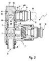
- FIGS 3 to 5 show the connection device 1 in the different equipment variants, with the base unit 3 in Figure 3 with the first venting unit 4a, in Figure 4 with the second ventilation unit 4b and in Figure 5 is equipped with the third ventilation unit 4c.
- the base unit 3 has an elongated fastening part 7 with opposite first and second end regions 8, 9. At the first end area 8 there is a working connection 12 provided, a vent connection at the second end region 9 13th
- a pivot part 14 is rotatable on the fastening part 7 attached. There is a sideways projecting feed connection on it 15 provided.
- the first interface 5 is located at the vent connection 13 and enables the aforementioned optional connection the ventilation units 4, with a mechanical and a fluidic connection between the base unit 3 and the relevant ventilation unit 4 is produced.
- the working connection 2 serves to connect the connection device 1 with the fluid technology component already mentioned 2.
- the working connection 12 via a connecting thread 16, with which it turns into a complementary Fastening thread 17 of the fluidic component 2 producing both mechanical and fluidic Connection is screwable ( Figure 3).
- the feed connector 15 is for connecting one in FIG. 3 Provided by dash-dotted lines fluid line 18 which is required for the operation of the fluid power component 2 Pressure medium - here: compressed air - from a pressure source is fed.
- Connecting the fluid line 18 can be done by a simple plug connection, to which Purpose of the supply connection 15 with suitable plug connection means 22 is equipped. The inserted fluid line 18 is held under seal. If necessary can the fluid line 18 by appropriate actuation of the Plug connection means 22 can be pulled out again at any time.
- the supply connection 15 for connecting the Fluid line 18 also have screw connection means 23, such as they are indicated by dash-dotted lines in FIG. 1. It deals here in particular an internal thread into which a provided with an external thread fluid line under sealing can be screwed in.
- the swivel part 14 is provided with a quick exhaust valve 24 equipped that in the connection between the three connections 12, 13, 15 is switched on. It's like one so-called shuttle valve built.
- a valve member is a movable sealing sleeve 25 is provided, which in the pivoting part 14 is integrated.
- the swivel part 14 contains a swivel part base body 26, which has an annular body 27 which is coaxial with the fastening part 7 is attached. A protrudes from the ring body 27 Pipe section 28 of the swivel part base body 26 transversely to the longitudinal axis 32 of the fastening part 7 away, in the from the free end forth a feed connection body having the feed connection 15 33 is inserted.
- the feed connector body is preferred 33 screwed into the pipe section 28 with sealing.
- the sealing sleeve 25 is between the swivel base body 26 and the feed connector body 33, wherein but in the longitudinal direction of the feed connector body 33 between two end positions is movable.
- the sealing sleeve 25 sits in a receiving space 34, the dividing them into a first chamber 35 and a second chamber 36.
- the supply connection opens into the first chamber 15 communicating first fluid channel 37.
- In the fastening part 7 assigned second chamber 36 opens out with the Second fluid channel 38 communicating work port 12 and a communicating with the vent port 13 third fluid channel 39.
- the latter two fluid channels 38, 39 each end at the other end on the assigned first and second end regions 8, 9 and each contain one between the outer periphery of the fastening part 7 and the ring channel 42 defined the inner circumference of the ring body 27 or 43, of which a branch channel leading into the first chamber 35 44 or 45 of the pivot part 14 goes off.
- the sealing sleeve 25 contains a central body 46 on which a circumferential sealing lip 47 is formed.
- connection device 1 allows through the optional combination the base unit 3 with one of the provided Ventilation units 4 the respective circumstances to take optimal account.
- the corresponding ventilation unit 4 with its second interface 6 at the second end region 9 of the fastening part 7 provided first interface 5 attached.
- FIG 3 shows the connection device 1 in the with the mentioned first venting unit 4, 4a equipped Status.
- This first ventilation unit 4, 4a is equipped with a Exhaust throttle 48 and equipped with a silencer 51.
- the preferably variably adjustable exhaust air throttle 48 enables the outflow speed to be influenced the compressed air, which in connection with fluid-operated drives especially used to speed to influence the drive part, for example a piston.
- Silencer 51 is the sound of the exiting Air and thus the operating noise of the connection device 1 steamed.
- FIG. 4 shows the connection device 1 in the second Venting unit 4, 4b equipped state. This contains no exhaust throttle 48 and allows an unrestricted Outflow of compressed air. However, here too a silencer 51 is provided for noise reduction.
- the venting unit 4c has no throttling means.
- a fluid line connection 52 is provided, to which a Connect further fluid line 53 indicated by dash-dotted lines leaves, so that the exhaust air can be exhausted and not in the immediate vicinity of the connection device 1 flows out.
- the fluid line port 52 is expediently provided with plug connection means 54 which sealing a detachable plug connection of the others Allow fluid line 53.
- the first and second interfaces 5, 6 are preferred Screw interfaces designed. They allow attachment the respective ventilation unit 4 in the context of a Screwing.
- the first interface 5 in an extension of the third fluid channel 39 an internal thread included, in which the ventilation unit 4 with an external thread having fastening attachment 55 screwed is.
- the attachment extension 55 is part of a banjo bolt 56 of the relevant ventilation unit 4. This has on the the end opposite the attachment extension 55 a e.g. Actuating part 57 formed by a polygon on which the banjo bolt 56 can be handled when it is in the fastening part 7 screwed in or unscrewed from this becomes.
- a ventilation channel 58 is located in the hollow screw 56. One ends at the area of the second interface 6 off, so that with the ventilation unit 4 installed the third fluid channel 39 of the base unit 3 in fluidic Connection is established.
- the ventilation channel 58 opens to the outer circumference of the Hollow screw 56, which was distributed over several circumferences Branch channels 59 can happen.
- the silencer 51 a sleeve-like shape. It is coaxial with the Banjo bolt 56 plugged in and at the level of the mouths of the Branch channels 59 placed. Coaxial between the silencer 51 and the outer circumference of the hollow screw 56 is a Annulus 63 in which the outflowing air is distributed may before it passes through the muffler 51.
- the muffler 51 consists of muffler material known per se, for example a sintered material, and has one porous structure that allows air to flow through allows simultaneous noise reduction.
- the banjo bolts are identical educated. Overall, the arrangement differs 5 used third venting unit 4, 4c of the second used in the arrangement according to FIG. 4 Ventilation unit 4b only in that instead of the silencer 51 a further pivot part 64 on the banjo bolt 56 is arranged rotatably, the fluid line connection 52nd and which includes an internal fluid channel 65 which connects the fluid line connection 52 to the annular space 63.
- seals 66 are provided axially on both sides of the annular space 63.
- Comparable seals 67 are located axially on both sides of the two annular spaces provided on the base unit 3 between the fastening part 7 and the swivel part 14.
- the first ventilation unit 4a according to FIG. 3 differs differs from the second ventilation unit 4b according to FIG. 4 due to the additional presence of an exhaust throttle 48.
- the exhaust throttle 48 expediently contains the actuating section 57 coaxial throttle element 68, the immersed in the ventilation duct 58.
- the throttle member 68 is adjustable and positionable relative to banjo bolt 56, different immersion depths and therefore different Obtain throttling intensities. To set this is Throttle member 68 at the outer end with an operating section 69 provided.
- connection device can be retrofitted at any time 1 to another type of ventilation unit 4 possible.
- the above-mentioned feed connector body 33 is on one Interface 73 of the swivel base body 26 is mounted.
- This interface 73 expediently enables the optional Attachment of supply connection bodies different Type. So, from case to case, optional supply connection bodies to be assembled, which is in the design distinguish the supply connection 15. This enables, for example the installation of supply connections 15 with different Connection sizes or with different types Connection means, for example in the form of Plug connection means 22 or screw connection means 23. In this way, there is also a high degree of variability Regarding the connection options for the compressed air supplying fluid line 18.
Landscapes
- Engineering & Computer Science (AREA)
- General Engineering & Computer Science (AREA)
- Mechanical Engineering (AREA)
- Joints Allowing Movement (AREA)
- Quick-Acting Or Multi-Walled Pipe Joints (AREA)
Abstract
Description
- Figur 1
- eine bevorzugte Bauform der erfindungsgemäßen Anschlussvorrichtung im Längsschnitt, wobei mehrere alternativ an der Basiseinheit der Anschlussvorrichtung festlegbare Entlüftungseinheiten schematisch strichpunktiert angedeutet sind,
- Figur 2
- eine Draufsicht auf die Basiseinheit der Anschlussvorrichtung aus Figur 1,
- Figur 3
- eine Längsschnittdarstellung der Anschlussvorrichtung aus Figur 1, ausgestattet mit einer einen Schalldämpfer und eine Abluftdrossel enthaltenden Entlüftungseinheit, wobei strichpunktiert ein Ausschnitt einer fluidtechnischen Komponente illustriert ist, an der die Anschlussvorrichtung festlegbar ist,
- Figur 4
- in Längsschnittdarstellung die Anschlussvorrichtung aus Figur 1, ausgestattet mit einer Entlüftungseinheit ohne Abluftdrossel, jedoch mit Schalldämpfer, und
- Figur 5
- eine Längsschnittdarstellung der Anschlussvorrichtung aus Figur 1, ausgestattet mit einer Entlüftungseinheit ohne Abluftdrossel und mit einem Fluidleitungsanschluss zur gefassten Luftabfuhr.
Claims (15)
- Anschlussvorrichtung für Fluidleitungen, mit einer Basiseinheit (3), die ein längliches Befestigungsteil (7) mit einander entgegengesetzten ersten und zweiten Endbereichen (8, 9) aufweist, auf das ein Schwenkteil (14) drehbar aufgesteckt ist, das einen Speiseanschluss (15) aufweist, der zum Anschließen einer ein Druckmedium einspeisenden Fluidleitung (18) vorgesehen ist,
mit einem am ersten Endbereich (8) des Befestigungsteiles (7) vorgesehenen Arbeitsanschluss (12) zum Verbinden mit einer fluidtechnischen Komponente (2) und einem am zweiten Endbereich (9) des Befestigungsteiles (7) vorgesehenen Entlüftungsanschluss (13), wobei das Schwenkteil (14) mit einem in die Verbindung zwischen den drei Anschlüssen (12, 13, 15) eingeschalteten Schnellentlüftungsventil (24) ausgestattet ist, und mit einer dem Entlüftungsanschluss (13) zugeordneten ersten Schnittstelle (5) am Befestigungsteil (7), die vorgesehen ist, um wahlweise unterschiedliche Typen von Entlüftungseinheiten (4) zu befestigen, unter denen sich wenigstens eine Entlüftungseinheit (4a) mit Abluftdrossel (48) und wenigstens eine Entlüftungseinheit (4b, 4c) ohne Abluftdrossel befindet und die jeweils mit einer zu der ersten Schnittstelle (5) komplementären zweiten Schnittstelle (6) versehen sind. - Anschlussvorrichtung nach Anspruch 1, dadurch gekennzeichnet, dass die dem Entlüftungsanschluss (13) zugeordnete erste Schnittstelle (5) eine Schraub-Schnittstelle ist.
- Anschlussvorrichtung nach Anspruch 1 oder 2, dadurch gekennzeichnet, dass die ersten und zweiten Schnittstellen (5, 6) zur lösbaren Befestigung der Entlüftungseinheiten (4) am Basisteil (7) ausgebildet sind.
- Anschlussvorrichtung nach einem der Ansprüche 1 bis 3, dadurch gekennzeichnet, dass mindestens eine der Entlüftungseinheiten (4, 4a, 4b) einen Schalldämpfer zur Dämpfung des Schalls der austretenden Luft enthält.
- Anschlussvorrichtung nach einem der Ansprüche 1 bis 4, dadurch gekennzeichnet, dass mindestens eine der Entlüftungseinheiten (4, 4c) mit einem Fluidleitungsanschluss (52) versehen ist, der zum Anschließen einer zur gefassten Luftabfuhr dienenden Fluidleitung (53) vorgesehen ist.
- Anschlussvorrichtung nach Anspruch 5, dadurch gekennzeichnet, dass der Fluidleitungsanschluss (52) mit Steckanschlussmitteln (54) ausgestattet ist.
- Anschlussvorrichtung nach Anspruch 5 oder 6, dadurch gekennzeichnet, dass die zur gefassten Luftabfuhr dienende Entlüftungseinheit (4, 4c) eine mit der zweiten Schnittstelle (6) versehene Hohlschraube (56) und ein drehbar auf die Hohlschraube (56) aufgestecktes, den Fluidleitungsanschluss (52) aufweisendes Schwenkteil (64) enthält.
- Anschlussvorrichtung nach einem der Ansprüche 1 bis 7, gekennzeichnet durch drei wahlweise an der ersten Schnittstelle (5) anbringbare Entlüftungseinheiten (4a, 4b, 4c), wobei eine erste Entlüftungseinheit (4a) mit einer Abluftdrossel (48) und einem Schalldämpfer (51) ausgestattet ist, eine zweite Entlüftungseinheit (4b) mit einem Schalldämpfer (51) und ohne Abluftdrossel ausgestattet ist und eine dritte Entlüftungseinheit (4c) mit einem der gefassten Luftabfuhr dienenden Fluidleitungsanschluss (52) und ohne Schalldämpfer und Abluftdrossel ausgestattet ist.
- Anschlussvorrichtung nach einem der Ansprüche 1 bis 8, dadurch gekennzeichnet, dass dem Arbeitsanschluss (12) ein zur Schraubbefestigung der Anschlussvorrichtung (1) vorgesehenes Anschlussgewinde (16) zugeordnet ist.
- Anschlussvorrichtung nach einem der Ansprüche 1 bis 9, dadurch gekennzeichnet, dass der Speiseanschluss (15) mit Steckanschlussmitteln (22) ausgestattet ist.
- Anschlussvorrichtung nach einem der Ansprüche 1 bis 10, dadurch gekennzeichnet, dass der Speiseanschluss (15) mit Schraubanschlussmitteln (23) ausgestattet ist.
- Anschlussvorrichtung nach einem der Ansprüche 1 bis 11, dadurch gekennzeichnet, dass das Schwenkteil (14) einen am Befestigungsteil (7) drehbar gelagerten Schwenkteil-Grundkörper (26) und einen den Speiseanschluss (15) aufweisenden, an dem Schwenkteil-Grundkörper (26) befestigten Speiseanschlusskörper (33) enthält.
- Anschlussvorrichtung nach Anspruch 12, dadurch gekennzeichnet, dass das Schnellentlüftungsventil (24) eine Dichtmanschette (25) enthält, die zwischen dem Schwenkteil-Grundkörper (26) und dem Speiseanschlusskörper (33) beweglich gefangen ist.
- Anschlussvorrichtung nach einem der Ansprüche 1 bis 13, gekennzeichnet durch mehrere unterschiedliche Typen von Speiseanschlusskörpern (33).
- Anschlussvorrichtung nach Anspruch 13 oder 14, gekennzeichnet durch eine an dem Schwenkteil-Grundkörper (26) vorgesehene Schnittstelle (73) zur wahlweisen Befestigung von Speiseanschlusskörpern (33) unterschiedlichen Typs, unter denen sich zweckmäßigerweise mindestens ein mit Steckanschlussmitteln (22) ausgestatteter Speiseanschlusskörper (33) und mindestens ein mit Schraubanschlussmitteln (23) ausgestatteter Speiseanschlusskörper (33) befindet.
Priority Applications (2)
| Application Number | Priority Date | Filing Date | Title |
|---|---|---|---|
| EP20020012669 EP1369633B1 (de) | 2002-06-07 | 2002-06-07 | Anschlussvorrichtung für Fluidleitungen |
| DE50207494T DE50207494D1 (de) | 2002-06-07 | 2002-06-07 | Anschlussvorrichtung für Fluidleitungen |
Applications Claiming Priority (1)
| Application Number | Priority Date | Filing Date | Title |
|---|---|---|---|
| EP20020012669 EP1369633B1 (de) | 2002-06-07 | 2002-06-07 | Anschlussvorrichtung für Fluidleitungen |
Publications (2)
| Publication Number | Publication Date |
|---|---|
| EP1369633A1 true EP1369633A1 (de) | 2003-12-10 |
| EP1369633B1 EP1369633B1 (de) | 2006-07-12 |
Family
ID=29433127
Family Applications (1)
| Application Number | Title | Priority Date | Filing Date |
|---|---|---|---|
| EP20020012669 Expired - Lifetime EP1369633B1 (de) | 2002-06-07 | 2002-06-07 | Anschlussvorrichtung für Fluidleitungen |
Country Status (2)
| Country | Link |
|---|---|
| EP (1) | EP1369633B1 (de) |
| DE (1) | DE50207494D1 (de) |
Cited By (8)
| Publication number | Priority date | Publication date | Assignee | Title |
|---|---|---|---|---|
| FR2891890A1 (fr) * | 2005-10-06 | 2007-04-13 | Renault Sas | Dispositif contre les projections d'un raccord hydraulique |
| WO2007107199A1 (de) | 2006-03-17 | 2007-09-27 | Festo Ag & Co. Kg | Anschlussvorrichtung für druckluftleitungen sowie damit ausgestattete pneumatikzylinderanordnung |
| EP1978262A1 (de) * | 2007-04-03 | 2008-10-08 | Festo AG & Co. KG | Antriebsvorrichtung |
| FR2915786A1 (fr) * | 2007-05-03 | 2008-11-07 | Legris Sa | Raccord de type bloqueur a clapet et purge |
| FR2915787A1 (fr) * | 2007-05-03 | 2008-11-07 | Legris Sa | Raccord de type bloqueur a clapet et moyens d'equilibrage de pression |
| DE102010017998A1 (de) * | 2010-04-23 | 2011-10-27 | Markus Kress | Druckbehälter |
| EP2503205A1 (de) * | 2011-03-22 | 2012-09-26 | Elastotec GmbH | Sicherheitsventil |
| CN108266581A (zh) * | 2018-03-28 | 2018-07-10 | 嘉兴迈思特管件制造有限公司 | 一种卡套式铰接式管接头 |
Citations (10)
| Publication number | Priority date | Publication date | Assignee | Title |
|---|---|---|---|---|
| GB878480A (en) * | 1957-12-18 | 1961-10-04 | Rockwell Standard Co | A compacted foraminous body suitable for use as a sound attenuating device |
| FR2352188A1 (fr) * | 1976-05-18 | 1977-12-16 | Bouteille Daniel | Dispositif de purge rapide d'une chambre d'un verin pneumatique |
| US4142741A (en) * | 1976-03-15 | 1979-03-06 | Ermeto-Armaturen Gmbh | Pivotal screwed fitting |
| US4690035A (en) * | 1984-01-17 | 1987-09-01 | La Telemecanique Electrique | Emergency draining device for stopping pneumatic cylinders |
| DE3739981A1 (de) * | 1986-12-10 | 1988-06-16 | Wirth & Schwaar Fluidtech Ag | Schnellentlueftungsventil |
| EP0520212A1 (de) * | 1991-06-24 | 1992-12-30 | Smc Kabushiki Kaisha | Geschwindigkeitssteuerung |
| DE9415871U1 (de) | 1994-10-01 | 1995-11-02 | Mosmatic AG Maschinen- und Apparatefabrik, Necker | Winkeldrehgelenk mit verbesserter Abdichtung |
| US6056325A (en) * | 1998-04-27 | 2000-05-02 | Francis Torq/Lite | Swivel body for fluid driven torque wrenches |
| DE20008129U1 (de) | 2000-05-05 | 2000-08-10 | Festo AG & Co, 73734 Esslingen | Anschlußteil für Fluidleitungen |
| US6202785B1 (en) * | 1999-06-02 | 2001-03-20 | 3M Innovative Properties Company | Muffler with acoustic absorption insert for limited clearance pneumatic device applications |
-
2002
- 2002-06-07 EP EP20020012669 patent/EP1369633B1/de not_active Expired - Lifetime
- 2002-06-07 DE DE50207494T patent/DE50207494D1/de not_active Expired - Lifetime
Patent Citations (10)
| Publication number | Priority date | Publication date | Assignee | Title |
|---|---|---|---|---|
| GB878480A (en) * | 1957-12-18 | 1961-10-04 | Rockwell Standard Co | A compacted foraminous body suitable for use as a sound attenuating device |
| US4142741A (en) * | 1976-03-15 | 1979-03-06 | Ermeto-Armaturen Gmbh | Pivotal screwed fitting |
| FR2352188A1 (fr) * | 1976-05-18 | 1977-12-16 | Bouteille Daniel | Dispositif de purge rapide d'une chambre d'un verin pneumatique |
| US4690035A (en) * | 1984-01-17 | 1987-09-01 | La Telemecanique Electrique | Emergency draining device for stopping pneumatic cylinders |
| DE3739981A1 (de) * | 1986-12-10 | 1988-06-16 | Wirth & Schwaar Fluidtech Ag | Schnellentlueftungsventil |
| EP0520212A1 (de) * | 1991-06-24 | 1992-12-30 | Smc Kabushiki Kaisha | Geschwindigkeitssteuerung |
| DE9415871U1 (de) | 1994-10-01 | 1995-11-02 | Mosmatic AG Maschinen- und Apparatefabrik, Necker | Winkeldrehgelenk mit verbesserter Abdichtung |
| US6056325A (en) * | 1998-04-27 | 2000-05-02 | Francis Torq/Lite | Swivel body for fluid driven torque wrenches |
| US6202785B1 (en) * | 1999-06-02 | 2001-03-20 | 3M Innovative Properties Company | Muffler with acoustic absorption insert for limited clearance pneumatic device applications |
| DE20008129U1 (de) | 2000-05-05 | 2000-08-10 | Festo AG & Co, 73734 Esslingen | Anschlußteil für Fluidleitungen |
Cited By (10)
| Publication number | Priority date | Publication date | Assignee | Title |
|---|---|---|---|---|
| FR2891890A1 (fr) * | 2005-10-06 | 2007-04-13 | Renault Sas | Dispositif contre les projections d'un raccord hydraulique |
| WO2007107199A1 (de) | 2006-03-17 | 2007-09-27 | Festo Ag & Co. Kg | Anschlussvorrichtung für druckluftleitungen sowie damit ausgestattete pneumatikzylinderanordnung |
| CN101405531B (zh) * | 2006-03-17 | 2011-01-26 | 费斯托股份有限两合公司 | 用于压缩空气管道的连接装置以及相应配备的气动缸装置 |
| EP1978262A1 (de) * | 2007-04-03 | 2008-10-08 | Festo AG & Co. KG | Antriebsvorrichtung |
| FR2915786A1 (fr) * | 2007-05-03 | 2008-11-07 | Legris Sa | Raccord de type bloqueur a clapet et purge |
| FR2915787A1 (fr) * | 2007-05-03 | 2008-11-07 | Legris Sa | Raccord de type bloqueur a clapet et moyens d'equilibrage de pression |
| DE102010017998A1 (de) * | 2010-04-23 | 2011-10-27 | Markus Kress | Druckbehälter |
| DE102010017998B4 (de) * | 2010-04-23 | 2017-06-08 | Markus Kress | Drucksprühgerät |
| EP2503205A1 (de) * | 2011-03-22 | 2012-09-26 | Elastotec GmbH | Sicherheitsventil |
| CN108266581A (zh) * | 2018-03-28 | 2018-07-10 | 嘉兴迈思特管件制造有限公司 | 一种卡套式铰接式管接头 |
Also Published As
| Publication number | Publication date |
|---|---|
| DE50207494D1 (de) | 2006-08-24 |
| EP1369633B1 (de) | 2006-07-12 |
Similar Documents
| Publication | Publication Date | Title |
|---|---|---|
| EP3248733B1 (de) | Spannvorrichtung | |
| DE9110959U1 (de) | Pneumatischer Membranstellantrieb | |
| DE19918560B4 (de) | Luftzuführ- und Abführsystem für pneumatisches Werkzeug | |
| DE10015165B4 (de) | Vorrichtung zur Zuführung von Druckmittel | |
| DE102019121433B4 (de) | Fluidrückführvorrichtung für einen doppeltwirkenden Zylinder und Verfahren zum Betreiben eines solchen Zylinders | |
| WO2008014829A1 (de) | Fluidtechnische vorrichtung | |
| DE3130292C2 (de) | Schalldämpfer zur Verwendung an druckluftbetriebenen Einrichtungen | |
| EP1502659B1 (de) | Farbwechselventilanordnung einer Beschichtungsanlage | |
| DE102004015594B4 (de) | Spindelvorrichtung für eine Werkzeugmaschine | |
| EP1369633B1 (de) | Anschlussvorrichtung für Fluidleitungen | |
| EP0590339B1 (de) | Wegeventil | |
| EP1249619B1 (de) | Ventileinheit mit entsperrbarem Rückschlagventil und damit ausgestatteter fluidbetätigter Antrieb | |
| EP0615729A1 (de) | Ärztliches, insbesondere zahnärztliches Instrument mit innen gekühltem Werkzeug | |
| EP4296001A1 (de) | Spannvorrichtung | |
| DE112017003127B4 (de) | Geschwindigkeitssteuerung | |
| DE2855575C2 (de) | Hydraulische Bohrmaschine | |
| EP0439242B1 (de) | Lineareinheit | |
| DE3441468C2 (de) | ||
| DE102004057974A1 (de) | Extrusionskopf mit Düsenspalteinstellung | |
| DE4101248C2 (de) | Strömungsventil | |
| EP1460276A2 (de) | Pneumatikzylinder mit Dämpfungsmitteln seitens des Enddeckels | |
| DE10164256A1 (de) | Vorrichtung zur Steuerung von Blasluft | |
| DE19630477A1 (de) | Offenend-Spinnvorrichtung | |
| EP4265396B1 (de) | Vorrichtung zur extrusionsbasierten additiven herstellung eines dreidimensionalen objekts | |
| DE2113166A1 (de) | Absaugevorrichtung |
Legal Events
| Date | Code | Title | Description |
|---|---|---|---|
| PUAI | Public reference made under article 153(3) epc to a published international application that has entered the european phase |
Free format text: ORIGINAL CODE: 0009012 |
|
| AK | Designated contracting states |
Kind code of ref document: A1 Designated state(s): AT BE CH CY DE DK ES FI FR GB GR IE IT LI LU MC NL PT SE TR |
|
| AX | Request for extension of the european patent |
Extension state: AL LT LV MK RO SI |
|
| 17P | Request for examination filed |
Effective date: 20040323 |
|
| 17Q | First examination report despatched |
Effective date: 20040623 |
|
| AKX | Designation fees paid |
Designated state(s): DE FR GB IT |
|
| GRAP | Despatch of communication of intention to grant a patent |
Free format text: ORIGINAL CODE: EPIDOSNIGR1 |
|
| GRAS | Grant fee paid |
Free format text: ORIGINAL CODE: EPIDOSNIGR3 |
|
| GRAA | (expected) grant |
Free format text: ORIGINAL CODE: 0009210 |
|
| AK | Designated contracting states |
Kind code of ref document: B1 Designated state(s): DE FR GB IT |
|
| PG25 | Lapsed in a contracting state [announced via postgrant information from national office to epo] |
Ref country code: IT Free format text: LAPSE BECAUSE OF FAILURE TO SUBMIT A TRANSLATION OF THE DESCRIPTION OR TO PAY THE FEE WITHIN THE PRE;WARNING: LAPSES OF ITALIAN PATENTS WITH EFFECTIVE DATE BEFORE 2007 MAY HAVE OCCURRED AT ANY TIME BEFORE 2007. THE CORRECT EFFECTIVE DATE MAY BE DIFFERENT FROM THE ONE RECORDED.SCRIBED TIME-LIMIT Effective date: 20060712 |
|
| REG | Reference to a national code |
Ref country code: GB Ref legal event code: FG4D Free format text: NOT ENGLISH |
|
| GBT | Gb: translation of ep patent filed (gb section 77(6)(a)/1977) |
Effective date: 20060712 |
|
| REF | Corresponds to: |
Ref document number: 50207494 Country of ref document: DE Date of ref document: 20060824 Kind code of ref document: P |
|
| ET | Fr: translation filed | ||
| PLBE | No opposition filed within time limit |
Free format text: ORIGINAL CODE: 0009261 |
|
| STAA | Information on the status of an ep patent application or granted ep patent |
Free format text: STATUS: NO OPPOSITION FILED WITHIN TIME LIMIT |
|
| 26N | No opposition filed |
Effective date: 20070413 |
|
| PGFP | Annual fee paid to national office [announced via postgrant information from national office to epo] |
Ref country code: GB Payment date: 20120516 Year of fee payment: 11 |
|
| PGFP | Annual fee paid to national office [announced via postgrant information from national office to epo] |
Ref country code: IT Payment date: 20120619 Year of fee payment: 11 |
|
| PGFP | Annual fee paid to national office [announced via postgrant information from national office to epo] |
Ref country code: FR Payment date: 20130703 Year of fee payment: 12 |
|
| GBPC | Gb: european patent ceased through non-payment of renewal fee |
Effective date: 20130607 |
|
| PG25 | Lapsed in a contracting state [announced via postgrant information from national office to epo] |
Ref country code: GB Free format text: LAPSE BECAUSE OF NON-PAYMENT OF DUE FEES Effective date: 20130607 |
|
| PG25 | Lapsed in a contracting state [announced via postgrant information from national office to epo] |
Ref country code: IT Free format text: LAPSE BECAUSE OF NON-PAYMENT OF DUE FEES Effective date: 20130607 |
|
| REG | Reference to a national code |
Ref country code: FR Ref legal event code: ST Effective date: 20150227 |
|
| PG25 | Lapsed in a contracting state [announced via postgrant information from national office to epo] |
Ref country code: FR Free format text: LAPSE BECAUSE OF NON-PAYMENT OF DUE FEES Effective date: 20140630 |
|
| PGFP | Annual fee paid to national office [announced via postgrant information from national office to epo] |
Ref country code: DE Payment date: 20150428 Year of fee payment: 14 |
|
| REG | Reference to a national code |
Ref country code: DE Ref legal event code: R119 Ref document number: 50207494 Country of ref document: DE |
|
| PG25 | Lapsed in a contracting state [announced via postgrant information from national office to epo] |
Ref country code: DE Free format text: LAPSE BECAUSE OF NON-PAYMENT OF DUE FEES Effective date: 20170103 |