EP1369836A1 - Brandmelder sowie Verfahren zum Betrieb eines Brandmelders - Google Patents
Brandmelder sowie Verfahren zum Betrieb eines Brandmelders Download PDFInfo
- Publication number
- EP1369836A1 EP1369836A1 EP02010414A EP02010414A EP1369836A1 EP 1369836 A1 EP1369836 A1 EP 1369836A1 EP 02010414 A EP02010414 A EP 02010414A EP 02010414 A EP02010414 A EP 02010414A EP 1369836 A1 EP1369836 A1 EP 1369836A1
- Authority
- EP
- European Patent Office
- Prior art keywords
- signal
- control
- unit
- control loop
- transmitter
- Prior art date
- Legal status (The legal status is an assumption and is not a legal conclusion. Google has not performed a legal analysis and makes no representation as to the accuracy of the status listed.)
- Granted
Links
Images


Classifications
-
- G—PHYSICS
- G08—SIGNALLING
- G08B—SIGNALLING SYSTEMS, e.g. PERSONAL CALLING SYSTEMS; ORDER TELEGRAPHS; ALARM SYSTEMS
- G08B17/00—Fire alarms; Alarms responsive to explosion
- G08B17/10—Actuation by presence of smoke or gases, e.g. automatic alarm devices for analysing flowing fluid materials by the use of optical means
- G08B17/103—Actuation by presence of smoke or gases, e.g. automatic alarm devices for analysing flowing fluid materials by the use of optical means using a light emitting and receiving device
- G08B17/107—Actuation by presence of smoke or gases, e.g. automatic alarm devices for analysing flowing fluid materials by the use of optical means using a light emitting and receiving device for detecting light-scattering due to smoke
-
- G—PHYSICS
- G08—SIGNALLING
- G08B—SIGNALLING SYSTEMS, e.g. PERSONAL CALLING SYSTEMS; ORDER TELEGRAPHS; ALARM SYSTEMS
- G08B29/00—Checking or monitoring of signalling or alarm systems; Prevention or correction of operating errors, e.g. preventing unauthorised operation
- G08B29/18—Prevention or correction of operating errors
- G08B29/20—Calibration, including self-calibrating arrangements
- G08B29/24—Self-calibration, e.g. compensating for environmental drift or ageing of components
Definitions
- the invention relates to a hazard detector for the detection of Fire and smoke that works according to the scattered light principle.
- the invention also relates to a method of operation of such a fire alarm.
- Hazard detectors of the type mentioned above have a measuring volume on, usually through a measuring chamber against light from Is shielded on the outside. The extraneous light is through a labyrinth held that there is a medium surrounding the measuring chamber such as smoke nevertheless allows into the measuring chamber penetrate.
- There is one transmitter and one in each measuring chamber Radiation receivers are arranged so that they are not direct Have visual contact and no radiation emitted by the transmitter hits the recipient directly.
- the radiation emitted by the transmitter is not only on Scattered smoke that is in the measuring chamber, but also reflected on the measuring chamber walls.
- the Basic signal is desirable on the one hand to the function of the transmitter to check, on the other hand it limits the detection possibilities strong one.
- the signal delivered by the receiver must be strong be reinforced.
- With high gain, the work area, the evaluation circuit following the amplifier stage are already completely claimed by the basic signal, whereby signal increases can no longer be recognized, and smoke detection is no longer possible. Accordingly poses the basic signal made it difficult to detect less Smoke densities. Nevertheless, smoke detectors are highly sensitive required for applications where smoke, too if it is heavily diluted, it can still be recognized as it is e.g. is the case in ventilation ducts or smoke extraction systems.
- the invention is therefore based on the object of a fire detector as well as a method for operating a fire detector at the beginning to provide mentioned type, with the help of which also strong diluted aerosols can be reliably recognized.
- the fire detector according to the invention has a transmitter which emits radiation into a measurement volume within a measurement chamber. Radiation that is scattered on the measuring chamber walls or on particles located in the measuring volume strikes a receiving device that converts the received radiation into an electrical signal and emits it at its output.
- the output of the receiving device is connected to a control circuit, the signal emitted by the receiving device being overlaid with an artificially generated signal.
- the control loop itself consists of a control device, an actuator and connecting lines. At its output, the control device emits a manipulated variable that is used as a superimposed signal.
- the output of the control device is connected to a first input of the actuator. A second input of the actuator is connected to the output of the receiving device.
- the output of the actuator, at which the actual value of the control loop is located, is connected to an alarm evaluation device and the input of the control device, a fire being detected by comparing the actual value of the control loop with an alarm threshold.
- the control device is designed so that the manipulated variable is only carried out very slowly on the one hand and is only carried out on the other hand if there is either a very high probability that there is no smoke in the measuring chamber or the temperature has changed.
- the control device has at its input a resettable minimum value and maximum value memory as well as a device for determining an average value, which is referred to below as average value images.
- the output of the mean value generator is connected to a first comparison point, at which the control deviation is determined as the difference between the target value and the mean value of the actual value.
- the output of the first comparison point is connected to a proportional element, in which the control deviation is multiplied by a factor k and a first correction value for the control is formed.
- the output of the proportional element is connected to a first input of a first comparator and to a first input of a first signal selection switch.
- the second inputs of the first comparator and the first signal selection switch are connected to a second maximum correction value.
- the output of the first comparator is connected to the control input of the first signal selection switch.
- the second maximum correction value is compared with the first correction value and, depending on the result of the comparison, the smaller of the two correction values is switched through from the first signal selection switch to its output.
- the output of the first signal selection switch is connected to the first input of an addition point.
- the old manipulated variable of the control loop is located at the second input of the addition point.
- the old control value and the correction value are summed in the addition point to form a new control value which is available at the output of the addition point.
- the output of the summer is connected to a first input of a second signal selection switch.
- the temperature-compensated old manipulated variable of the control circuit is located at the second input of the second signal selection switch.
- the new manipulated variable or the old, but temperature-compensated manipulated variable, of the control loop is switched through to the output.
- the output of the second signal selection switch is connected to a signal holding element which stores the value present at its input and outputs it again at its output.
- the output of the signal holding element is connected to the first input of the actuator, to the second input of the summer and to the input of the temperature compensation device.
- the output signal of the temperature compensation device is present at the second input of the second signal selection switch.
- the control input of the second signal selection switch is connected to the output of a second comparator, which compares the difference between the minimum and maximum actual value with a predetermined window value.
- a first input of the second comparator is connected to a memory for the window value and a second input to a second comparison point, the first input of which is connected to the output of the maximum value memory and the second input of which is connected to the output of the minimum value memory.
- the signal emitted by the receiving unit is superimposed before the final amplification with a superposition signal which is somewhat smaller in magnitude than the amount of the basic signal of the receiving unit and bears the opposite sign.
- the basic signal is the smoke-independent, quasi-static signal component of the receiving unit.
- the DC component of the signal to be amplified drops, the signal can be amplified to a higher level without fully controlling the subsequent stages with the DC component - this makes it easier to assess dynamic signal components and to detect signal increases caused by smoke.
- the basic signal fluctuates greatly due to component and manufacturing tolerances and changes over the course of life, a self-adapting overlay signal is necessary. Therefore, according to the invention, the beat signal is generated as a function of the basic signal emitted by the receiving unit.
- the signal delivered by the receiving unit is, for example in the control element of a control loop with the manipulated variable of Control circuit superimposed so that the manipulated variable from the received signal is subtracted.
- the difference between the two signals becomes so strong reinforces that signal fluctuations can be easily recognized.
- the signal formed in this way represents the actual value on the one hand of the control loop, on the other hand it becomes an alarm evaluation used by it with a predetermined alarm threshold is compared. Because the actual value in a control loop but is usually kept largely constant, the The actual value normally never reaches the alarm threshold.
- the control device To at If smoke occurs, the actual value increases up to the alarm threshold the control device nevertheless enables make sure that the manipulated variable (superimposed signal) is only updated will, if there is a very high probability that no Smoke is in the measuring chamber and that the tracking of the Manipulated value is slower than it is for the regulation of a due to the occurrence of smoke the expected signal increase is necessary would.
- the tracking of the Manipulated value limited to a maximum tracking value, whereby the tracking only took place after one over several measurements Averaging of the actual value is carried out.
- the difference between the largest and smallest actual value becomes one Measurement series compared with a window value. If the difference exceeds the window value, the control value is updated interrupted. If the updating of the actual value is interrupted is, but can still be an adjustment of the manipulated variable change in temperature.
- the invention is based on the knowledge that for one is the radiation reflected on the walls of the measuring chamber an essentially constant, only over long periods of time delivers very slowly changing basic signal and in short Intervals carried out only due to signal noise deliver different values. These measurements have a certain characteristic spread.
- the smoke to be recognized consists of small, constantly particles in motion. Scattered on these particles and causes radiation incident on a receiver a signal that has values that are significantly broader, as the basic signal for a smoke-free measuring chamber.
- a first Evidence of the existence of smoke can be obtained.
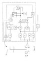
- the signal processing unit (10) is shown in FIG.
- the Receiver unit (1) receives on measuring chamber walls and smoke or other aerosols scattered radiation and converts this into electrical signal at the output of the receiving unit (1) is tapped.
- the output of the receiving unit (1) is with the second input of the actuator (2) of the control circuit (5) connected.
- the first input of the actuator (2) is with the output connected to the control device (4) on which the manipulated variable provided.
- the manipulated variable and the signal from the receiving unit (2) is superimposed on one another.
- the difference between the two signals is amplified and thus at the output of the Actuator (2) delivered as the actual value of the control loop (5).
- the output of the actuator (2) is with the input of the alarm evaluation device (3) and the entrance of the control device (4) connected.
- the alarm evaluation device (3) works just as it does from conventional flare light detectors is known, e.g. by simply comparing the on her Input pending signal with an alarm threshold while the control device largely changes only the basic signal balances.
- the control device (4) contains one at its input Minimum value memory (6), a maximum value memory (7) and an average value image (8).
- the reference junction (9) which, from the measured values of a measuring cycle of, for example 8 measurements formed mean, with the setpoint (11) of the control loop (5) compared, and the control deviation determined.
- the control deviation is shown in the proportional element (12) with a Factor multiplied and thus a first tracking value for the manipulated variable is determined.
- This tracking value becomes the first Input of the signal selection circuit (13) and the comparator (14) fed.
- the comparator (14) the first tracking value and the maximum tracking value (15) compared.
- the comparator (14) then controls the signal selection switch (13) so that the smaller of the two tracking values to the addition point (16) is switched through.
- the old manipulated variable with the smaller tracking value becomes new manipulated variable is added and to the first input of the signal selection switch (17) created.
- the new manipulated variable is from Signal selection switch (17) only to the signal holding element (18) and thus switched to the actuator (2) when the comparison in the comparator (19) has shown that in the reference junction (20) difference formed from that in the maximum value memory (7) stored maximum value and in the minimum value memory (6) stored minimum value of a measuring cycle, is smaller than the window value (21). If the difference is out Maximum and minimum value of the measuring cycle larger than the window value (21) is not the new manipulated variable, but the in the temperature compensation device (22) temperature-compensated, old manipulated variable to the signal holding element (18) and thus switched through to the actuator (2). This is the regulation almost frozen.
- FIG. 2 A preferred exemplary embodiment can be seen in FIG compared to Figure 2, a further comparator (23) in the control device (4) is inserted, which is the actual value with half Compares alarm threshold, and its output signal with the Output signal of the comparator (19) orodized in the OR element (24) becomes.
- the output of the OR element (24) now controls the signal selection switch (17), so that in addition, even if the Actual value is a predefined threshold, in the example half the alarm threshold reached, the control is frozen.
- a control unit (5) in a fire detector according to the invention can be implemented in an ASIC, for example, or also in the form of suitable software in a microprocessor be implemented, whereby the alarm evaluation unit (3) can be implemented in the same microprocessor or ASIC.
- To the Inputs and outputs of the control unit (4) are in use analogue-digital converters corresponding to a processor or digital ASICs or digital-to-analog converter.
- the invention is a fire detector according to Steulichtkar and a method for its operation, in which another signal is superimposed on the received signal by a to enable high signal amplification.
Landscapes
- Physics & Mathematics (AREA)
- General Physics & Mathematics (AREA)
- Chemical & Material Sciences (AREA)
- Analytical Chemistry (AREA)
- Business, Economics & Management (AREA)
- Emergency Management (AREA)
- Engineering & Computer Science (AREA)
- Computer Security & Cryptography (AREA)
- Fire-Detection Mechanisms (AREA)
- Fire Alarms (AREA)
- Investigating Or Analysing Materials By Optical Means (AREA)
Abstract
Description
An ihrem Ausgang gibt die Regeleinrichtung, eine Stellgröße, die als Überlagerungssignal verwendet wird, ab. Der Ausgang der Regeleinrichtung ist mit einem ersten Eingang des Stellgliedes verbunden. Ein zweiter Eingang des Stellgliedes ist mit dem Ausgang der Empfangseinrichtung verbunden. Der Ausgang des Stellgliedes, an dem der Istwert des Regelkreises liegt, ist mit einer Alarmauswerteeinrichtung und dem Eingang der Regeleinrichtung verbunden, wobei ein Brand erkannt wird, indem der Istwert des Regelkreises mit einer Alarmschwelle verglichen wird. Um das Erkennen eines Brandes am Istwert des Regelkreises zu ermöglichen, die ist Regeleinrichtung so ausgeführt, dass ein Nachführen der Stellgröße zum einen nur sehr langsam durchgeführt wird und zum anderen nur dann durchgeführt wird, wenn sich entweder mit sehr hoher Wahrscheinlichkeit kein Rauch in der Messkammer befindet, oder sich die Temperatur geändert hat.
Dem erfindungsgemäßen Verfahren nach wird das von der Empfangseinheit abgegebene Signal noch vor der endgültigen Verstärkung mit einem Überlagerungssignal überlagert, das dem Betrag nach etwas kleiner als der Betrag des Grundsignals der Empfangseinheit ist und das entgegengesetzte Vorzeichen trägt. Das Grundsignal ist der Rauch-unabhängige, quasi statische Signalanteil der Empfangseinheit. Durch diese Maßnahme, sinkt der Gleichanteil des zu verstärkenden Signals, das Signal kann höher verstärkt werden, ohne die nachfolgenden Stufen bereits durch den Gleichanteil voll auszusteuern, - dadurch können dynamische Signalanteile leichter beurteilt und durch Rauch bedingte Signalanstiege leichter erkannt werden. Da das Grundsignal aber aufgrund von Bauteil- und Fertigungstoleranzen stark schwankt und sich im Laufe der Lebenszeit ändert, ist ein sich selbst anpassendes Überlagerungssignal nötig. Daher wird erfindungsgemäß das Überlagerungssignal in Abhängigkeit von dem von der Empfangseinheit abgegebenen Grundsignal erzeugt.
- Fig. 1
- ein vereinfachtes Blockschaltbild der Signalverarbeitung eines erfindungsgemäßen Brandmelders,
- Fig. 2
- ein Blockschaltbild der Signalverarbeitung eines erfindungsgemäßen Brandmelders mit Darstellung der Regeleinrichtung, und
- Fig. 3
- eine bevorzugte Ausführungsform der Signalverarbeitung eines erfindungsgemäßen Brandmelders.
Claims (11)
- Brandmelder mit einer Messkammer, einem Sender und einer Signalverarbeitungseinheit mit einer Empfangseinheit zum Empfang von vom Sender abgegebener und an Rauch oder anderen Aerosolen gestreuter Strahlung und einer Alarmauswerteeinheit, dadurch gekennzeichnet, dass die Signalverarbeitungseinheit einen Regelkreis mit einer Regelungseinheit enthält, und die Stellgröße des Regelkreises dem Ausgangssignal der Empfangseinheit überlagert ist.
- Brandmelder nach Anspruch 1, dadurch gekennzeichnet, dass der Eingang der Alarmauswerteeinheit mit dem Istwert des Regelkreises verbunden ist.
- Brandmelder nach Anspruch 1 oder 2, dadurch gekennzeichnet, dass die Regelungseinheit Mittel enthält, die die Nachführung der Regelung verlangsamen und/oder beschränken.
- Brandmelder nach einem oder mehreren der vorangegangenen Ansprüche, dadurch gekennzeichnet, dass die Regelungseinheit Mittel enthält, die die Nachführung der Regelung, durch den Vergleich von absoluten oder statistisch ermittelten Werten, aus Größen des Regelkreises mit vorgegebenen Grenzen, unterbrechen können.
- Verfahren zum Betrieb eines insbesondere gemäß zumindest einem der Ansprüche 1 bis 4 ausgestalteten Brandmelders mit einer Messkammer, einem Sender und einer Signalverarbeitungseinheit mit einer Empfangseinheit zum Empfang von vom Sender abgegebener und an Rauch oder anderen Aerosolen gestreuter Strahlung und einer Alarmauswerteeinheit, dadurch gekennzeichnet, dass das von der Empfangseinheit abgegebene Signal mit einem Überlagerungssignal überlagert wird bevor es der Alarmauswerteeinheit zugeführt wird, und die Summe beider Signale kleiner als das von der Empfangseinheit abgegebene Signal ist.
- Verfahren nach Anspruch 5, dadurch gekennzeichnet, dass das die Höhe des Überlagerungssignals in Abhängigkeit der Höhe des durch das Gundsignal gebildeten Gleichanteils im von der Empfangseinheit abgegebenen Signal bestimmt wird.
- Verfahren nach den Ansprüchen 5 und/oder 6 dadurch gekennzeichnet, dass das Überlagerungssignal als Stellgröße eines Regelkreis gebildet wird.
- Verfahren zum Betrieb eines Brandmelders, insbesondere gemäß zumindest einem der vorstehenden Ansprüche, mit einer Messkammer, einem Sender und einer Signalverarbeitungseinheit mit einer Empfangseinheit zum Empfang von vom Sender abgegebener und an Rauch oder anderen Aerosolen gestreuter Strahlung und einer Alarmauswerteeinheit, dadurch gekennzeichnet, dass ein Alarm anhand des Istwertes eines Regelkreises bestimmt wird.
- Verfahren nach Anspruch 8 dadurch gekennzeichnet, dass die Regelung im Regelkreis so verlangsamt und beschränkt wird, dass die Regeleinheit einen durch Rauch bedingten Istwertanstieg des Regelkreises nicht mehr ausregeln kann.
- Verfahren nach Anspruch 8 dadurch gekennzeichnet, dass die Nachführung der Regelung unterbrochen wird, wenn aus Größen des Regelkreises statistisch ermittelte oder absolute Werte vorgegebene Grenzwerte überschreiten.
- Verfahren nach den Ansprüchen 8 und/oder10 dadurch gekennzeichnet, dass die Nachführung der Regelung unterbrochen wird, wenn die Differenz aus maximalem und minimalem Istwert einer Messreihe einen Fensterwert überschreitet.
Priority Applications (5)
| Application Number | Priority Date | Filing Date | Title |
|---|---|---|---|
| DE50205343T DE50205343D1 (de) | 2002-05-08 | 2002-05-08 | Brandmelder sowie Verfahren zum Betrieb eines Brandmelders |
| AT02010414T ATE313836T1 (de) | 2002-05-08 | 2002-05-08 | Brandmelder sowie verfahren zum betrieb eines brandmelders |
| DK02010414T DK1369836T3 (da) | 2002-05-08 | 2002-05-08 | Brandalarm og fremgangsmåde til drift af en brandalarm |
| ES02010414T ES2254552T3 (es) | 2002-05-08 | 2002-05-08 | Detector de incendio y procedimiento de funcionamiento del mismo. |
| EP02010414A EP1369836B1 (de) | 2002-05-08 | 2002-05-08 | Brandmelder sowie Verfahren zum Betrieb eines Brandmelders |
Applications Claiming Priority (1)
| Application Number | Priority Date | Filing Date | Title |
|---|---|---|---|
| EP02010414A EP1369836B1 (de) | 2002-05-08 | 2002-05-08 | Brandmelder sowie Verfahren zum Betrieb eines Brandmelders |
Publications (2)
| Publication Number | Publication Date |
|---|---|
| EP1369836A1 true EP1369836A1 (de) | 2003-12-10 |
| EP1369836B1 EP1369836B1 (de) | 2005-12-21 |
Family
ID=29433073
Family Applications (1)
| Application Number | Title | Priority Date | Filing Date |
|---|---|---|---|
| EP02010414A Expired - Lifetime EP1369836B1 (de) | 2002-05-08 | 2002-05-08 | Brandmelder sowie Verfahren zum Betrieb eines Brandmelders |
Country Status (5)
| Country | Link |
|---|---|
| EP (1) | EP1369836B1 (de) |
| AT (1) | ATE313836T1 (de) |
| DE (1) | DE50205343D1 (de) |
| DK (1) | DK1369836T3 (de) |
| ES (1) | ES2254552T3 (de) |
Cited By (2)
| Publication number | Priority date | Publication date | Assignee | Title |
|---|---|---|---|---|
| WO2019089450A1 (en) | 2017-10-30 | 2019-05-09 | Carrier Corporation | Compensator in a detector device |
| US12614437B2 (en) | 2022-11-28 | 2026-04-28 | Kidde Fire Protection, Llc | Fire alarm device and system |
Citations (4)
| Publication number | Priority date | Publication date | Assignee | Title |
|---|---|---|---|---|
| US4225791A (en) * | 1979-03-01 | 1980-09-30 | Honeywell Inc. | Optical smoke detector circuit |
| US4514720A (en) * | 1981-07-10 | 1985-04-30 | Siemens Aktiengesellschaft | Method and apparatus for increasing the response sensitivity and the interference resistance in an alarm system |
| US5523743A (en) * | 1995-04-13 | 1996-06-04 | Digital Security Controls Ltd. | Self-diagnostic smoke detector |
| EP1098284A2 (de) * | 1999-11-05 | 2001-05-09 | E.I. Technology Limited | Rauchalarmvorrichtung |
-
2002
- 2002-05-08 EP EP02010414A patent/EP1369836B1/de not_active Expired - Lifetime
- 2002-05-08 AT AT02010414T patent/ATE313836T1/de active
- 2002-05-08 DE DE50205343T patent/DE50205343D1/de not_active Expired - Lifetime
- 2002-05-08 DK DK02010414T patent/DK1369836T3/da active
- 2002-05-08 ES ES02010414T patent/ES2254552T3/es not_active Expired - Lifetime
Patent Citations (4)
| Publication number | Priority date | Publication date | Assignee | Title |
|---|---|---|---|---|
| US4225791A (en) * | 1979-03-01 | 1980-09-30 | Honeywell Inc. | Optical smoke detector circuit |
| US4514720A (en) * | 1981-07-10 | 1985-04-30 | Siemens Aktiengesellschaft | Method and apparatus for increasing the response sensitivity and the interference resistance in an alarm system |
| US5523743A (en) * | 1995-04-13 | 1996-06-04 | Digital Security Controls Ltd. | Self-diagnostic smoke detector |
| EP1098284A2 (de) * | 1999-11-05 | 2001-05-09 | E.I. Technology Limited | Rauchalarmvorrichtung |
Cited By (5)
| Publication number | Priority date | Publication date | Assignee | Title |
|---|---|---|---|---|
| WO2019089450A1 (en) | 2017-10-30 | 2019-05-09 | Carrier Corporation | Compensator in a detector device |
| CN111263958A (zh) * | 2017-10-30 | 2020-06-09 | 开利公司 | 检测器装置中的补偿器 |
| US11568730B2 (en) | 2017-10-30 | 2023-01-31 | Carrier Corporation | Compensator in a detector device |
| US11790751B2 (en) | 2017-10-30 | 2023-10-17 | Carrier Corporation | Compensator in a detector device |
| US12614437B2 (en) | 2022-11-28 | 2026-04-28 | Kidde Fire Protection, Llc | Fire alarm device and system |
Also Published As
| Publication number | Publication date |
|---|---|
| DE50205343D1 (de) | 2006-01-26 |
| ATE313836T1 (de) | 2006-01-15 |
| EP1369836B1 (de) | 2005-12-21 |
| ES2254552T3 (es) | 2006-06-16 |
| DK1369836T3 (da) | 2006-05-01 |
Similar Documents
| Publication | Publication Date | Title |
|---|---|---|
| DE19934171B4 (de) | Filtersystem und -verfahren | |
| DE69624461T2 (de) | Feuermeldesystem mit Unterscheidung von Rauchpartikeln | |
| DE69903190T2 (de) | Rauchmeldung | |
| AT397578B (de) | Brandmeldeanlage | |
| EP2603907B1 (de) | Auswerten von streulichtsignalen bei einem optischen gefahrenmelder sowie ausgeben einer staub- / dampf-warnung oder eines brandalarms | |
| DE2032438B2 (de) | Vorrichtung zur regelung des vorspannstromes fuer einen photodetektor | |
| EP0070449B1 (de) | Verfahren und Anordnung zur Erhöhung der Ansprechempfindlichkeit und der Störsicherheit in einer Gefahren-, insbesondere Brandmeldeanlage | |
| EP1293727B1 (de) | Regeleinrichtung für einen Brenner und Einstellverfahren | |
| WO2005069242A1 (de) | Brandmelder mit mehreren untersuchungsvolumina | |
| EP0530723A1 (de) | Optischer Rauchmelder mit aktiver Überwachung | |
| EP2601644A1 (de) | Auswerten von streulichtsignalen bei einem optischen gefahrenmelder und ausgeben sowohl eines gewichteten rauchdichtesignals als auch eines gewichteten staub-/dampfdichte-signals | |
| WO2006037804A1 (de) | Streulicht-rauchmelder | |
| CH668658A5 (de) | Photoelektrischer rauchsensor. | |
| DE2822547A1 (de) | Vorrichtung zur ueberpruefung des schwebstoffgehalts der atmosphaere, insbesondere zur verwendung als rauchmelder | |
| DE3603568C2 (de) | ||
| EP0039761A2 (de) | Verfahren zur Brandmeldung und Brandmeldeanlage | |
| CH669859A5 (de) | ||
| CH681932A5 (de) | ||
| DE3905261C2 (de) | ||
| EP1369836B1 (de) | Brandmelder sowie Verfahren zum Betrieb eines Brandmelders | |
| DE102017127963A1 (de) | Schaltungsanordnung zum Erfassen von Licht | |
| EP0750764A1 (de) | Verfahren und anordnung zur fuzzy-regelung | |
| EP1638062B1 (de) | Ansaugender Brandmelder und Verfahren zu dessen Betrieb | |
| DE69313739T2 (de) | Rauchdetektierungsvorrichtung für Feueralarm | |
| DE4334625A1 (de) | Verfahren zum Konstanthalten der Leistung eines Wassererwärmers |
Legal Events
| Date | Code | Title | Description |
|---|---|---|---|
| PUAI | Public reference made under article 153(3) epc to a published international application that has entered the european phase |
Free format text: ORIGINAL CODE: 0009012 |
|
| 17P | Request for examination filed |
Effective date: 20030104 |
|
| AK | Designated contracting states |
Kind code of ref document: A1 Designated state(s): AT BE CH CY DE DK ES FI FR GB GR IE IT LI LU MC NL PT SE TR |
|
| AX | Request for extension of the european patent |
Extension state: AL LT LV MK RO SI |
|
| AKX | Designation fees paid |
Designated state(s): AT BE CH CY DE DK ES FI FR GB GR IE IT LI LU MC NL PT SE TR |
|
| GRAP | Despatch of communication of intention to grant a patent |
Free format text: ORIGINAL CODE: EPIDOSNIGR1 |
|
| GRAS | Grant fee paid |
Free format text: ORIGINAL CODE: EPIDOSNIGR3 |
|
| GRAA | (expected) grant |
Free format text: ORIGINAL CODE: 0009210 |
|
| AK | Designated contracting states |
Kind code of ref document: B1 Designated state(s): AT BE CH CY DE DK ES FI FR GB GR IE IT LI LU MC NL PT SE TR |
|
| PG25 | Lapsed in a contracting state [announced via postgrant information from national office to epo] |
Ref country code: IE Free format text: LAPSE BECAUSE OF FAILURE TO SUBMIT A TRANSLATION OF THE DESCRIPTION OR TO PAY THE FEE WITHIN THE PRESCRIBED TIME-LIMIT Effective date: 20051221 |
|
| REG | Reference to a national code |
Ref country code: GB Ref legal event code: FG4D Free format text: NOT ENGLISH |
|
| REG | Reference to a national code |
Ref country code: CH Ref legal event code: EP |
|
| REG | Reference to a national code |
Ref country code: IE Ref legal event code: FG4D Free format text: LANGUAGE OF EP DOCUMENT: GERMAN |
|
| REF | Corresponds to: |
Ref document number: 50205343 Country of ref document: DE Date of ref document: 20060126 Kind code of ref document: P |
|
| REG | Reference to a national code |
Ref country code: CH Ref legal event code: NV Representative=s name: HANS RUDOLF GACHNANG PATENTANWALT |
|
| PG25 | Lapsed in a contracting state [announced via postgrant information from national office to epo] |
Ref country code: GR Free format text: LAPSE BECAUSE OF FAILURE TO SUBMIT A TRANSLATION OF THE DESCRIPTION OR TO PAY THE FEE WITHIN THE PRESCRIBED TIME-LIMIT Effective date: 20060321 |
|
| REG | Reference to a national code |
Ref country code: SE Ref legal event code: TRGR |
|
| GBT | Gb: translation of ep patent filed (gb section 77(6)(a)/1977) |
Effective date: 20060405 |
|
| REG | Reference to a national code |
Ref country code: DK Ref legal event code: T3 |
|
| PG25 | Lapsed in a contracting state [announced via postgrant information from national office to epo] |
Ref country code: PT Free format text: LAPSE BECAUSE OF FAILURE TO SUBMIT A TRANSLATION OF THE DESCRIPTION OR TO PAY THE FEE WITHIN THE PRESCRIBED TIME-LIMIT Effective date: 20060522 |
|
| PG25 | Lapsed in a contracting state [announced via postgrant information from national office to epo] |
Ref country code: MC Free format text: LAPSE BECAUSE OF NON-PAYMENT OF DUE FEES Effective date: 20060531 |
|
| REG | Reference to a national code |
Ref country code: ES Ref legal event code: FG2A Ref document number: 2254552 Country of ref document: ES Kind code of ref document: T3 |
|
| ET | Fr: translation filed | ||
| REG | Reference to a national code |
Ref country code: IE Ref legal event code: FD4D |
|
| PLBE | No opposition filed within time limit |
Free format text: ORIGINAL CODE: 0009261 |
|
| STAA | Information on the status of an ep patent application or granted ep patent |
Free format text: STATUS: NO OPPOSITION FILED WITHIN TIME LIMIT |
|
| 26N | No opposition filed |
Effective date: 20060922 |
|
| PG25 | Lapsed in a contracting state [announced via postgrant information from national office to epo] |
Ref country code: TR Free format text: LAPSE BECAUSE OF FAILURE TO SUBMIT A TRANSLATION OF THE DESCRIPTION OR TO PAY THE FEE WITHIN THE PRESCRIBED TIME-LIMIT Effective date: 20051221 |
|
| PG25 | Lapsed in a contracting state [announced via postgrant information from national office to epo] |
Ref country code: CY Free format text: LAPSE BECAUSE OF FAILURE TO SUBMIT A TRANSLATION OF THE DESCRIPTION OR TO PAY THE FEE WITHIN THE PRESCRIBED TIME-LIMIT Effective date: 20051221 |
|
| PGFP | Annual fee paid to national office [announced via postgrant information from national office to epo] |
Ref country code: DK Payment date: 20090526 Year of fee payment: 8 Ref country code: ES Payment date: 20090522 Year of fee payment: 8 Ref country code: NL Payment date: 20090527 Year of fee payment: 8 |
|
| PGFP | Annual fee paid to national office [announced via postgrant information from national office to epo] |
Ref country code: FI Payment date: 20090525 Year of fee payment: 8 Ref country code: FR Payment date: 20090519 Year of fee payment: 8 Ref country code: IT Payment date: 20090526 Year of fee payment: 8 Ref country code: LU Payment date: 20090525 Year of fee payment: 8 Ref country code: SE Payment date: 20090525 Year of fee payment: 8 |
|
| PGFP | Annual fee paid to national office [announced via postgrant information from national office to epo] |
Ref country code: BE Payment date: 20090526 Year of fee payment: 8 |
|
| PGFP | Annual fee paid to national office [announced via postgrant information from national office to epo] |
Ref country code: GB Payment date: 20090528 Year of fee payment: 8 |
|
| BERE | Be: lapsed |
Owner name: *HEKATRON TECHNIK G.M.B.H. Effective date: 20100531 |
|
| REG | Reference to a national code |
Ref country code: NL Ref legal event code: V1 Effective date: 20101201 |
|
| REG | Reference to a national code |
Ref country code: DK Ref legal event code: EBP |
|
| GBPC | Gb: european patent ceased through non-payment of renewal fee |
Effective date: 20100508 |
|
| PG25 | Lapsed in a contracting state [announced via postgrant information from national office to epo] |
Ref country code: FI Free format text: LAPSE BECAUSE OF NON-PAYMENT OF DUE FEES Effective date: 20100508 |
|
| EUG | Se: european patent has lapsed | ||
| REG | Reference to a national code |
Ref country code: FR Ref legal event code: ST Effective date: 20110131 |
|
| PG25 | Lapsed in a contracting state [announced via postgrant information from national office to epo] |
Ref country code: IT Free format text: LAPSE BECAUSE OF NON-PAYMENT OF DUE FEES Effective date: 20100508 Ref country code: BE Free format text: LAPSE BECAUSE OF NON-PAYMENT OF DUE FEES Effective date: 20100531 Ref country code: NL Free format text: LAPSE BECAUSE OF NON-PAYMENT OF DUE FEES Effective date: 20101201 Ref country code: SE Free format text: LAPSE BECAUSE OF NON-PAYMENT OF DUE FEES Effective date: 20100509 |
|
| PG25 | Lapsed in a contracting state [announced via postgrant information from national office to epo] |
Ref country code: DK Free format text: LAPSE BECAUSE OF NON-PAYMENT OF DUE FEES Effective date: 20100531 |
|
| PG25 | Lapsed in a contracting state [announced via postgrant information from national office to epo] |
Ref country code: FR Free format text: LAPSE BECAUSE OF NON-PAYMENT OF DUE FEES Effective date: 20100531 |
|
| REG | Reference to a national code |
Ref country code: ES Ref legal event code: FD2A Effective date: 20110714 |
|
| PG25 | Lapsed in a contracting state [announced via postgrant information from national office to epo] |
Ref country code: GB Free format text: LAPSE BECAUSE OF NON-PAYMENT OF DUE FEES Effective date: 20100508 Ref country code: ES Free format text: LAPSE BECAUSE OF NON-PAYMENT OF DUE FEES Effective date: 20110704 |
|
| PGFP | Annual fee paid to national office [announced via postgrant information from national office to epo] |
Ref country code: CH Payment date: 20110525 Year of fee payment: 10 |
|
| PGFP | Annual fee paid to national office [announced via postgrant information from national office to epo] |
Ref country code: AT Payment date: 20110520 Year of fee payment: 10 |
|
| PG25 | Lapsed in a contracting state [announced via postgrant information from national office to epo] |
Ref country code: ES Free format text: LAPSE BECAUSE OF NON-PAYMENT OF DUE FEES Effective date: 20100509 |
|
| PGFP | Annual fee paid to national office [announced via postgrant information from national office to epo] |
Ref country code: DE Payment date: 20110404 Year of fee payment: 10 |
|
| PG25 | Lapsed in a contracting state [announced via postgrant information from national office to epo] |
Ref country code: LU Free format text: LAPSE BECAUSE OF NON-PAYMENT OF DUE FEES Effective date: 20100508 |
|
| REG | Reference to a national code |
Ref country code: CH Ref legal event code: PL |
|
| REG | Reference to a national code |
Ref country code: AT Ref legal event code: MM01 Ref document number: 313836 Country of ref document: AT Kind code of ref document: T Effective date: 20120508 |
|
| PG25 | Lapsed in a contracting state [announced via postgrant information from national office to epo] |
Ref country code: AT Free format text: LAPSE BECAUSE OF NON-PAYMENT OF DUE FEES Effective date: 20120508 Ref country code: LI Free format text: LAPSE BECAUSE OF NON-PAYMENT OF DUE FEES Effective date: 20120531 Ref country code: CH Free format text: LAPSE BECAUSE OF NON-PAYMENT OF DUE FEES Effective date: 20120531 |
|
| REG | Reference to a national code |
Ref country code: DE Ref legal event code: R119 Ref document number: 50205343 Country of ref document: DE Effective date: 20121201 |
|
| PG25 | Lapsed in a contracting state [announced via postgrant information from national office to epo] |
Ref country code: DE Free format text: LAPSE BECAUSE OF NON-PAYMENT OF DUE FEES Effective date: 20121201 |