EP1370099A2 - Mesures d'intensité de signaux GSM dans le mode compressé d'un terminal double mode GSM/UTRA FDD - Google Patents
Mesures d'intensité de signaux GSM dans le mode compressé d'un terminal double mode GSM/UTRA FDD Download PDFInfo
- Publication number
- EP1370099A2 EP1370099A2 EP03012224A EP03012224A EP1370099A2 EP 1370099 A2 EP1370099 A2 EP 1370099A2 EP 03012224 A EP03012224 A EP 03012224A EP 03012224 A EP03012224 A EP 03012224A EP 1370099 A2 EP1370099 A2 EP 1370099A2
- Authority
- EP
- European Patent Office
- Prior art keywords
- signal
- frequency
- power mode
- transmission signal
- transmitter
- Prior art date
- Legal status (The legal status is an assumption and is not a legal conclusion. Google has not performed a legal analysis and makes no representation as to the accuracy of the status listed.)
- Granted
Links
Images



Classifications
-
- H—ELECTRICITY
- H04—ELECTRIC COMMUNICATION TECHNIQUE
- H04W—WIRELESS COMMUNICATION NETWORKS
- H04W88/00—Devices specially adapted for wireless communication networks, e.g. terminals, base stations or access point devices
- H04W88/02—Terminal devices
- H04W88/06—Terminal devices adapted for operation in multiple networks or having at least two operational modes, e.g. multi-mode terminals
-
- H—ELECTRICITY
- H04—ELECTRIC COMMUNICATION TECHNIQUE
- H04W—WIRELESS COMMUNICATION NETWORKS
- H04W24/00—Supervisory, monitoring or testing arrangements
- H04W24/10—Scheduling measurement reports ; Arrangements for measurement reports
-
- H—ELECTRICITY
- H04—ELECTRIC COMMUNICATION TECHNIQUE
- H04W—WIRELESS COMMUNICATION NETWORKS
- H04W36/00—Hand-off or reselection arrangements
- H04W36/0005—Control or signalling for completing the hand-off
- H04W36/0083—Determination of parameters used for hand-off, e.g. generation or modification of neighbour cell lists
- H04W36/0085—Hand-off measurements
-
- Y—GENERAL TAGGING OF NEW TECHNOLOGICAL DEVELOPMENTS; GENERAL TAGGING OF CROSS-SECTIONAL TECHNOLOGIES SPANNING OVER SEVERAL SECTIONS OF THE IPC; TECHNICAL SUBJECTS COVERED BY FORMER USPC CROSS-REFERENCE ART COLLECTIONS [XRACs] AND DIGESTS
- Y02—TECHNOLOGIES OR APPLICATIONS FOR MITIGATION OR ADAPTATION AGAINST CLIMATE CHANGE
- Y02D—CLIMATE CHANGE MITIGATION TECHNOLOGIES IN INFORMATION AND COMMUNICATION TECHNOLOGIES [ICT], I.E. INFORMATION AND COMMUNICATION TECHNOLOGIES AIMING AT THE REDUCTION OF THEIR OWN ENERGY USE
- Y02D30/00—Reducing energy consumption in communication networks
- Y02D30/70—Reducing energy consumption in communication networks in wireless communication networks
Definitions
- the present invention relates to the field of frequency division duplex radio access telecommunication terminals and in particular to the measurement of the received signal strength of frequency channels within a transmission gap.
- UMTS Universal Mobile Telecommunications Standard
- UE User Equipment
- GSM Global System of Mobile communications
- the UMTS standard has defined periods in this continuous transmission where the transmitter and receiver within the UE are "powered down". These gaps are defined as the compressed mode, and as such the UE has the opportunity of making measurements of the received signal strength on other frequency channels. If the received signal strength on a different channel is stronger, the UE changes channel as commanded by the network's Radio Resource Management (RRM) that is in control of the Radio Link. This improves the quality of service to the UE. Additionally, this allows the UE to roam between broadcast cells.
- RRM Radio Resource Management
- the transmission of signals from the UE can be halted so as to reduce interference on the received channels that are being measured.
- both the UMTS standard and the GSM standard are supported. This means, during compressed mode, measurement of both the UMTS standard and the GSM standard received signals can be performed.
- the GSM measurement receiver switches on to begin taking the measurements of the other frequency channels.
- the measurements made by the GSM measurement receiver are carried out at the start of the compressed mode gap, if the UMTS transmitter is not fully powered down, interference can occur on the GSM measured signal, and therefore repeated measurements of the GSM signal may be required. This again increases power consumption within the UE.
- the present invention reduces the power consumed in a dual mode user equipment (UE) terminal by reducing the amounts of interference on a measured down link signal.
- UE user equipment
- the present invention determines when, during a reduced power level of the transmitter, to begin measuring the signal strength of the down link channels of the second signal type.
- a frequency division duplex radio access telecommunications terminal for transmission of a first signal type having a peak power level and a periodic reduced power level, and for reception of a second signal type different to the first signal type
- the terminal comprising a transmitter for transmitting a transmission signal of the first type at a first frequency, the transmitter being arranged to switch between a peak power mode in which the transmission signal is transmitted at a peak power level, and a reduced power mode; a receiver for receiving a reception signal of the second type and at a second frequency, different from the first frequency of the transmission signal; a detector for measuring the signal strength of the reception signal; and a controller in communication with the receiver, transmitter and detector, the controller being arranged to cause the detector to measure the signal strength of the reception signal whilst the transmitter is operating in- the reduced power mode, and at a predetermined time before the transmitter switches to the power mode.
- a method of measuring the strength of a received radio signal in a mobile telecommunications terminal comprising the steps of transmitting, at a first frequency, a transmission signal of a first signal type, the first signal type having a peak power level and a periodic reduced power level; switching the transmission signal between a peak power mode at a peak power level and a reduced power mode; receiving at a second frequency, different from the first frequency of the transmission signal, a reception signal of a second type, different to the first signal type; and measuring the signal strength of the reception signal whilst the transmission signal is in the reduced power mode, and at a predetermined time before the transmission signal is switched to the peak power level.
- the amount of interference on the second type down link signal being measured is further reduced by ordering the sequence in which the down link signals are measured, with the most interfering signals being ordered so that measurement of these occurs at a point during a reduced power mode of the UE transmitter, furthest from the peak power level of the UE transmitter.
- a frequency division duplex radio access telecommunications terminal for transmission of a first signal type having a peak power level and a periodic reduced power level, and for reception of a second signal type different to the first signal type
- the terminal comprising a transmitter for transmitting a transmission signal of the first type at a first frequency, the transmitter being arranged to switch between a peak power mode in which the transmission signal is transmitted at a peak power level, and a reduced power mode; a receiver for receiving a plurality of reception signals of the second type, each reception signal being at one of a further plurality of frequencies, different from the first frequency of the transmission signal; a detector for measuring the signal strength of the reception signals; and a controller in communication with the receiver, transmitter and detector, the controller being arranged to determine the order in which the detector measures each of the reception signals, based upon the degree of interference, in each case, between the transmission signal and the plurality of reception signals whose strength is to be measured.
- a method for ordering the measurement of the strength of a received radio signal in a mobile telecommunications terminal comprising the step of transmitting at a first frequency, a transmission signal of a first signal type, the first signal type having a peak power level and a periodic reduced power level; switching the transmission signal between a peak power mode at a peak power level at a reduced power mode; receiving a plurality of reception signals, each reception signal being at one of a further plurality of frequencies, different from the first signal type, at a second frequency, different to the frequency of the transmission signal; and determining the order in which each of the reception signals are measured, based upon the degree of interference, in each case, between the transmission signal and the plurality of reception signals whose strength is to be measured.
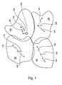
- FIG. 1 shows a perspective view of four communication cells 105.
- Each of the communication cells 105 is generated by a first, second, third and fourth base station 110,115,120,125 respectively.
- the cells 105 define an area, in which user equipment (UE) can communicate with one of the appropriate base stations 110,115,120,125.
- UE user equipment
- a UE 130 is in communication with the fourth base station 125.
- the UE 130 generates an "up link" signal 140 which is transmitted to and received by the fourth base station 125.
- the fourth base station 125 communicates with the UE 130 by generating a "down link" signal 135 which is received, and processed, by the UE 130.
- the mobile station is capable of generating the up link signal in accordance with one of two telecommunications standard.
- one standard is the Global System, for Mobile communication (GSM) and the other standard is the Universal Mobile Telecommunications Standard (UMTS).
- GSM Global System, for Mobile communication
- UMTS Universal Mobile Telecommunications Standard
- the present invention is not limited to the GSM and UMTS standard, and other standards such as CDMA-2000, EGSM and the like may be used instead.
- the frequency of the up link and down link signals will be operating at different frequencies.
- the UE 130 may roam between the different communication cells, and will therefore be capable of communicating with either the first, second or third base stations 110,115,120.
- down link signals 135,145 generated by either the first, second, third or fourth base stations 110,115,120,125 are received by the UE 130.
- the UE 130 must scan other frequency channels to determine which channel is most appropriate to continue communicating with the base station on. The UE determines this, from amongst other things, the strength of the received signal. This means that the UE 130 has to scan other down link signals on different frequencies from that with which it is currently receiving. This scanning procedure is known in the art. In the present case however, this frequency scanning takes place during the compressed mode of the UMTS standard.
- FIG. 2 shows a typical UMTS periodic signal pattern that is associated with the up link 205 and down link channels 210.
- the up link 205 and the down link channels 210 are transmitted on different frequencies.
- Each period in the UMTS signal pattern is composed of a length of time during which peak power transmission occurs 225 and a length of time in which the transmitted power of the up link and down link signals are a minimum 220.
- This minimum transmission period is called compressed mode 215.
- the time crap in UTRAN WCDMA compressed mode can vary from 3 to 14 timeslots over one or two 10 mS frames.
- Higher layer parameters are transmitted by the network that indicate the position and period of the compressed mode in the FDD frame structure.
- Compressed mode is a known feature of the UMTS standard. During compressed mode, the output from the UMTS transmitter is turned off in the UE and for the base station (node B) the transmitted signal to the specific UE is turned off (not the RF transmitter serving other UEs).
- the WCDMA system allows for simultaneous and non-simultaneous Uplink and Downlink compressed mode.
- GSM Global System for Mobile communications
- the GSM standard signals are time duplexed, there are prescribed times during which the GSM transmitter does not operate, and hence the GSM measurement receiver can measure other GSM down link channels. More specifically, in GSM there are eight time slots in each GSM uplink and downlink frame. The UE is allocated one of the eight slots for its uplink in the uplink frame and one slot for its downlink in the downlink frame. These two slots are allocated so that each UE is allocated an uplink time slot that is three slots after it receives any information from the allocated downlink time slot. Therefore the UE has two time slots idle from the moment it receives a command from downlink or four idle slots after its uplink transmission to the network for measurement. In GSM these idle slots can be used for system measurements similar to that created by compressed mode in UTRAN.
- FIG. 3 shows a detailed timing diagram 300 of the compressed mode transmission gap 215.
- a UMTS transceiver (not shown) is powered on.
- the UE 130 begins to enter compressed mode.
- the UMTS transceiver power would fall in accordance with the dashed line 311.
- the UE 130 enters the compressed mode at a second point depicted in Figure 3 at 306, which is a ramp down time (defined by line 309 in Figure 3) later.
- the UE 130 is powered at ramp up point 307 as it begins to leave compressed mode.
- the transceiver would resume full power in accordance with the dashed lines 325.
- the full power of transceiver does not begin (and therefore the UE 130 does not leave compressed mode) until point 335.
- the nature of the parasitic characteristics of the UMTS transceiver determines the ramp up and ramp down time, but this time can typically be 0.5mS to rise and 0.5mS to fall. This means, therefore, that there is a time gap of the order of 1ms between the point 306 and 307 when the UE 130 is operating in compressed mode while the transceiver is ramping up or down. It should be noted that 15 time slot in FDD WCDMA is 10 mS.
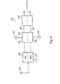
- FIG. 4 shows a block diagram of a receiver section of a radio access telecommunications terminal 400.
- An antenna 405 is connected to a receiver block 410.
- the antenna 405 is arranged to receive signals using both the GSM and UMTS standards as is understood.
- the receiver block 410 consists of a UMTS receiver 415 and a GSM receiver 420 (detector). Both the UMTS receiver 415 and the GSM receiver 420 are arranged to receive signals according to the appropriate standard.
- the UMTS receiver 415 and the GSM receiver 420 are attached to a down converter block 425.
- the down converter block 425 consists of a GSM down converter 435 and a UMTS down converter 430.
- first and second frequency synthesizer 440 and 445 are Also input to the down converter 425.
- the first frequency synthesizer 440 is connected to the GSM down converter 435 and the second frequency synthesizer 445 is connected to the UMTS down converter 430.
- the first and second frequency synthesizers 440, 445 are shown separately, it is anticipated that they may be incorporated into a single frequency synthesizer.
- the frequency of the signal generated by the first and second frequency synthesizers 440,445 is such that the output of the GSM and UMTS down converters 435,430 are of a constant intermediate frequency.
- a base band processor 460 comprises a GSM base band processor 465 and a UMTS base band processor 470.
- GSM intermediate frequency 450 is fed into the GSM base band processor 465 and the UMTS intermediate frequency 455 is fed into the UMTS base band processor 470.
- the GSM and UMTS base band processors 465,470 further down convert the intermediate frequency signal into a base band signal and also digitize the down converted signals for further processing by a processor.
- the processor is described, later, in relation to Figure 6.
- the GS1X measuring receiver 420 does not measure the signal strength of other down link frequency channels. This is because the UMTS internal circuitry will produce interference on the GSM receiver circuitry, and so may produce spurious signal measurements. In these circumstances, remeasurement or data retransmission would be required which reduces the battery life of the user equipment. Accordingly, the measurement of the UMTS and GSM down link channels are made within the time period defined between point 306 and 307 as depicted in Figure 3.
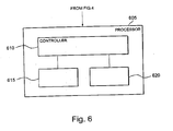
- a processor 605, as shown in Figure 6, is connected to each of the UMTS transmitter (not shown), the UMTS receiver 415, the GSM receiver 420 and the first and second frequency synthesizers 440,445. Accordingly, the processor controls the operation of at least the above components in the UE 130.
- the processor 605 contains a controller 610, a logical layer 1 and protocol stack 615 and a memory store 620.
- the protocol stack and logical layer 1 615 are programming functions that sequences commands to the controller 610 and is aware of the timing and manages the order of the measuring sequence, as would be appreciated by the skilled person.
- the protocol stack and logical layer 1 615 is connected to the controller 610.
- the controller is arranged to process the received digital signals as well as generate digital signals for transmission.
- the memory store 620 is connected to the controller 610 and is arranged to store, amongst other things, the details regarding the measurement times that are associated with the GSM receiver 420. The evaluation of the length of time that the GSM measurement receiver 420 takes to measure the different down link channels will now be described.
- the GSM receiver 420 is arranged to evaluate the time period that is required for it to make the signal strength measurements of other frequency GSM down link channels. There are a number of ways this may be achieved. As an example, during the test procedure at the point of manufacture, the GSM receiver 420 may be required to measure the strength of a particular GSM down link frequency channel. During this time, the GSM receiver may count the number of clock pulses, supplied by a clock, for example the processor clock, that is required to enable the GSM receiver 420 to measure the signal strength of the particular frequency channel. The number of clock pulses that is required will then be stored in the memory store 620 which is either contained within or is accessible to the processor. Additionally, the processor 605 can be further arranged periodically to check and update the stored value if necessary. This periodic updating has the advantage that as the components deteriorate over time, any alteration in the time that the GSM receiver 420 takes to make the signal strength measurements may be kept accurate.
- the latest time for the GSM measuring receiver 420 to begin measuring the different frequency down link channels in relation to the ramp up point 307 because the processor 605 controls when the UE 130 begins to leave compressed mode. Therefore, this ramp up point 307 is precisely defined by the processor 605.
- the minimum power point 306 is well defined, for example if the ramp down time 309 is measured during manufacture and stored in the memory store 620, then the latest time for the GSM measuring receiver 420 to begin measuring can be determined in relation to either the minimum power point 306 or the ramp down point 305.
- the GSM receiver 420 is inoperative whilst the UMTS transmitter is transmitting uplink signals or the UMTS receiver is receiving downlink signals and, as such, the GSM receiver enters a standby mode. Therefore, there is a delay present in preparing the GSM receiver 420 to make the signal strength measurements. This is depicted in Figure 3 by the receiver warm up time shown as line 311. Accordingly, the processor will need to calculate the latest activation time for the GSM receiver 420 to accommodate the preparation time. The latest activation time can therefore be defined as
- the time taken for preparing the GSM receiver 420 is evaluated in a similar manner to that as described above in relation to the receiver measurement period (line 340).
- the preparation time value is also stored in the memory store so that the processor may access the information.
- UMTS terrestrial radio access UTRA
- EGSM Enhanced GSM
- PCS Personal Communications System
- CDMA-2000 Code Division Multiple Access - 2000
- the measurement for a particular frequency channel may be conducted over one or more compressed mode time periods. For example, if the period required for measuring the GSM receiver signal is longer than the maximum period offered by the compressed mode as set by the network, the UE 130 is scheduled for the measurements to be conducted across several compressed mode gaps.
- the UMTS and GSM receivers 415,420 scan through other down link frequency channels that are different to the down link channel with which the UE 130 is communicating with the base station.
- the GSM receiver 420 is arranged to scan the down link channels during compressed mode, thus reducing the amount of interference on the measured signal, the level of interference is determined to a large extent by the frequency of the up link signal transmitted by the UE 130 and the frequency of the down link signal being measured. For example, an up link channel that is closer in frequency to the down link channel being measured produces a higher level of interference compared with an up link channel that has a frequency of operation that is as close.
- an up link frequency channel that has a frequency of operation that is a harmonic of the down link channel being measured also produces a high level of interference.
- the processor 605 is thus also configured further to reduce the level of interference by measuring the signal strength of the down link channels in a particular order during the compressed mode state. The ordering will be conducted by the processor 605 in accordance with Figure 5 that shows a flow diagram, used by the processor 605, for determining the preferred order in which to scan the frequency channels.
- the processor 605 contains a controller 610, a logical layer 1 and protocol stack 615 and a memory store 620.
- the protocol stack and logical layer 1 615 are programming functions that sequences command to the controller 610 and is aware of the timing and manages the order of the measuring sequence, as would be appreciated by the skilled person.
- the protocol stack and logical layer 1 615 is connected to the controller 610.
- the controller is arranged to process the received digital signals as well as generate digital signals for transmission.
- the memory store 620 is connected to the controller 610 and is arranged to store, amongst other things, the details regarding the measurement times that are associated with the GSM receiver 420.
- the logical layer 1 and protocol stack 615 is notified by the controller 610 that the GSM receiver 420 is to begin measuring the signal strength of the four channels. This notification will happen at a time defined by line 315 as shown in Figure 3.
- the logical layer 1 and protocol stack 615 has a list of the four channels that are to be scanned. This list is provided as the user equipment moves into a communication cell and begins communicating with a particular base station.
- the logical layer 1 and protocol stack 615 stores this list as a set of numbers known in the art as absolute radio frequency channel numbers (ARFCN). Each of these numbers has associated characteristics, for example, the frequency of the carrier of the channel.
- ARFCN absolute radio frequency channel numbers
- the logical layer 1 and protocol stack 615 provides the controller 610 with the detail, and order, of the frequency channels that are to be scanned by the GSM receiver 420.
- the uplink channel is operating at 900 MHz
- f 1 is operating at 2500 MHz
- f 2 is operating at 1800 MHz
- f 3 is operating at 2100 MHz
- f 4 is operating at 800 MHz.
- the protocol stack and logical layer 1 615 evaluates the channels f 1 , f 2 , f 3 , f 4 , in sequence.
- the protocol stack and logical layer 1 615 then ranks the channels by comparing the frequency of the scanned channel (fi) with the frequency of the uplink channel (ft) (step S1) .
- the ranking is conducted such that the scanned channel which is deemed to interfere most with the uplink channel is ranked highest and is measured nearest to point 307.
- the protocol stack and logical layer 1 615 may incorporate, into the ranking, a weighting factor.
- the weighting factor for a first order harmonic is a multiplier of 2. Therefore although f 2 previously was ranked number 3, with the weighting factor applied, f 2 is ranked number 6 (steps S5, S6). As there are only four possible channels to be scanned, f 2 will be scanned nearest point 307.
- weighting factors may be incorporated.
- a channel having a frequency of operation that is a second order harmonic of the uplink channel will increase interference (although the interference will not be as severe as is the case with a first order harmonic). Therefore, a weighting factor of 1.5 may be applied to the ranking in this case (steps S7, S8).
- the weighting factor would be a divisor.
Landscapes
- Engineering & Computer Science (AREA)
- Computer Networks & Wireless Communication (AREA)
- Signal Processing (AREA)
- Mobile Radio Communication Systems (AREA)
- Transceivers (AREA)
- Transmitters (AREA)
- Bidirectional Digital Transmission (AREA)
Applications Claiming Priority (2)
| Application Number | Priority Date | Filing Date | Title |
|---|---|---|---|
| GB0212987 | 2002-06-06 | ||
| GB0212987A GB2389484B (en) | 2002-06-06 | 2002-06-06 | A measurement technique for a radio access telecommunications terminal |
Publications (3)
| Publication Number | Publication Date |
|---|---|
| EP1370099A2 true EP1370099A2 (fr) | 2003-12-10 |
| EP1370099A3 EP1370099A3 (fr) | 2004-01-02 |
| EP1370099B1 EP1370099B1 (fr) | 2005-10-26 |
Family
ID=9938079
Family Applications (1)
| Application Number | Title | Priority Date | Filing Date |
|---|---|---|---|
| EP03012224A Expired - Lifetime EP1370099B1 (fr) | 2002-06-06 | 2003-06-06 | Mesures d'intensité de signaux GSM dans le mode compressé d'un terminal double mode GSM/UTRA FDD |
Country Status (6)
| Country | Link |
|---|---|
| US (1) | US7558532B2 (fr) |
| EP (1) | EP1370099B1 (fr) |
| JP (2) | JP4269154B2 (fr) |
| CN (1) | CN1254142C (fr) |
| DE (1) | DE60302007T2 (fr) |
| GB (2) | GB2421152B (fr) |
Cited By (1)
| Publication number | Priority date | Publication date | Assignee | Title |
|---|---|---|---|---|
| WO2005120093A1 (fr) * | 2004-06-04 | 2005-12-15 | Telefonaktiebolaget Lm Ericsson (Publ) | Mesures de force de signal dans des systemes de telecommunication cellulaire |
Families Citing this family (19)
| Publication number | Priority date | Publication date | Assignee | Title |
|---|---|---|---|---|
| GB2421152B (en) * | 2002-06-06 | 2006-11-22 | Nec Technologies | A measurement technique for a radio access telecommunications terminal |
| US6990362B2 (en) * | 2003-12-16 | 2006-01-24 | Motorola, Inc. | Communication unit energy conservation apparatus and method |
| US7537171B2 (en) * | 2004-11-17 | 2009-05-26 | Emerson Electric Co. | Thermostat control system providing power saving transmissions |
| ES2396147T3 (es) * | 2005-12-22 | 2013-02-19 | Koninklijke Philips Electronics N.V. | Estación de radio y método para operar una estación de radio |
| JP4793287B2 (ja) * | 2007-02-28 | 2011-10-12 | ブラザー工業株式会社 | 通信装置および通信システム |
| US8619601B2 (en) * | 2007-10-05 | 2013-12-31 | Blackberry Limited | Proximity of user equipment to a home local network |
| US8089933B2 (en) * | 2007-10-08 | 2012-01-03 | Research In Motion Limited | Inter-radio access technology measurement system and method |
| US8089942B2 (en) | 2007-10-09 | 2012-01-03 | Research In Motion Limited | System and method for inter-radio access technology signal measurement |
| US20090191883A1 (en) * | 2008-01-25 | 2009-07-30 | Infineon Technologies Ag | Method and device for transmitting data |
| KR20100030091A (ko) * | 2008-09-09 | 2010-03-18 | 삼성전자주식회사 | 듀얼 스탠바이 휴대 단말기 및 그의 통신 방법 |
| EP2242185A1 (fr) * | 2009-04-15 | 2010-10-20 | ST-NXP Wireless France | Suppression du bruit |
| AU2010202901B2 (en) | 2010-07-08 | 2016-04-14 | Patent Analytics Holding Pty Ltd | A system, method and computer program for preparing data for analysis |
| US8639695B1 (en) * | 2010-07-08 | 2014-01-28 | Patent Analytics Holding Pty Ltd | System, method and computer program for analysing and visualising data |
| CN102196542B (zh) * | 2011-05-27 | 2014-06-25 | 上海华为技术有限公司 | 功率控制方法、设备和系统 |
| CN105142205A (zh) * | 2015-06-12 | 2015-12-09 | 北京创毅视讯科技有限公司 | 一种专网通信中调整发射功率的方法和终端 |
| US11681017B2 (en) | 2019-03-12 | 2023-06-20 | Uhnder, Inc. | Method and apparatus for mitigation of low frequency noise in radar systems |
| US11953615B2 (en) | 2020-01-13 | 2024-04-09 | Uhnder Inc. | Method and system for antenna array calibration for cross-coupling and gain/phase variations in radar systems |
| CN113630135A (zh) * | 2021-08-12 | 2021-11-09 | 惠州Tcl云创科技有限公司 | 一种gsm杂散抑制方法、装置、终端设备及存储介质 |
| US12468011B2 (en) | 2022-06-07 | 2025-11-11 | Honeywell International Inc. | Systems and methods for mitigating telecommunications signal interference to radar altimeters |
Family Cites Families (14)
| Publication number | Priority date | Publication date | Assignee | Title |
|---|---|---|---|---|
| TW306102B (fr) | 1993-06-14 | 1997-05-21 | Ericsson Telefon Ab L M | |
| GB2297460B (en) | 1995-01-28 | 1999-05-26 | Motorola Ltd | Communications system and a method therefor |
| US5959980A (en) * | 1995-06-05 | 1999-09-28 | Omnipoint Corporation | Timing adjustment control for efficient time division duplex communication |
| US6023622A (en) | 1997-03-05 | 2000-02-08 | Watkins-Johnson Company | Wireless communication system with dynamic channel allocation |
| DE69942403D1 (de) | 1998-04-23 | 2010-07-01 | Mitsubishi Electric Corp | Empfänger zur Überwachung eines Kontrollkanals eines anderen Systems während eines Ruhezeitabschnitts in einem CDMA Mobilfunkkommunikationssystem |
| EP1081979A1 (fr) * | 1999-08-31 | 2001-03-07 | TELEFONAKTIEBOLAGET L M ERICSSON (publ) | Dispositif d'abonné, moyens de commande de réseau et méthode de déclenchement des mesures d'inter-fréquence dans un système de communication mobile |
| US6597679B1 (en) * | 1999-12-01 | 2003-07-22 | Telefonaktiebolat Lm Ericsson | Control of compressed mode transmission in WCDMA |
| DE10004278C1 (de) | 2000-02-01 | 2001-06-28 | Siemens Ag | Verfahren zur Intersystem-Verbindungsweiterschaltung |
| FI112772B (fi) * | 2000-02-18 | 2003-12-31 | Nokia Corp | Häiriön vähentäminen keskinäistaajuuksien mittauksessa |
| US6650905B1 (en) * | 2000-06-30 | 2003-11-18 | Nokia Mobile Phones, Ltd. | Universal mobile telecommunications system (UMTS) terrestrial radio access (UTRA) frequency division duplex (FDD) downlink shared channel (DSCH) power control in soft handover |
| US6980838B2 (en) * | 2001-05-10 | 2005-12-27 | Motorola, Inc. | Control channel to enable a low power mode in a wideband wireless communication system |
| US6615044B2 (en) * | 2001-06-06 | 2003-09-02 | Nokia Mobile Phones, Ltd. | Method of WCDMA coverage based handover triggering |
| US6618365B1 (en) * | 2002-04-29 | 2003-09-09 | Motorola, Inc. | Method and apparatus to reduce uplink compressed mode monitoring in a communication device |
| GB2421152B (en) * | 2002-06-06 | 2006-11-22 | Nec Technologies | A measurement technique for a radio access telecommunications terminal |
-
2002
- 2002-06-06 GB GB0516809A patent/GB2421152B/en not_active Expired - Fee Related
- 2002-06-06 GB GB0212987A patent/GB2389484B/en not_active Expired - Fee Related
-
2003
- 2003-06-05 US US10/454,549 patent/US7558532B2/en not_active Expired - Fee Related
- 2003-06-05 JP JP2003160356A patent/JP4269154B2/ja not_active Expired - Fee Related
- 2003-06-06 CN CNB031386679A patent/CN1254142C/zh not_active Expired - Fee Related
- 2003-06-06 EP EP03012224A patent/EP1370099B1/fr not_active Expired - Lifetime
- 2003-06-06 DE DE60302007T patent/DE60302007T2/de not_active Expired - Lifetime
-
2008
- 2008-12-22 JP JP2008324896A patent/JP4947317B2/ja not_active Expired - Fee Related
Cited By (2)
| Publication number | Priority date | Publication date | Assignee | Title |
|---|---|---|---|---|
| WO2005120093A1 (fr) * | 2004-06-04 | 2005-12-15 | Telefonaktiebolaget Lm Ericsson (Publ) | Mesures de force de signal dans des systemes de telecommunication cellulaire |
| US7366475B2 (en) | 2004-06-04 | 2008-04-29 | Telefonaktiebolaget Lm Ericsson (Publ) | Signal strength measurements in cellular telecommunication systems |
Also Published As
| Publication number | Publication date |
|---|---|
| GB0212987D0 (en) | 2002-07-17 |
| GB0516809D0 (en) | 2005-09-21 |
| JP2009065719A (ja) | 2009-03-26 |
| JP2004015809A (ja) | 2004-01-15 |
| EP1370099A3 (fr) | 2004-01-02 |
| US20030228890A1 (en) | 2003-12-11 |
| GB2421152B (en) | 2006-11-22 |
| GB2389484A (en) | 2003-12-10 |
| CN1254142C (zh) | 2006-04-26 |
| US7558532B2 (en) | 2009-07-07 |
| GB2389484B (en) | 2005-12-21 |
| DE60302007T2 (de) | 2006-04-20 |
| CN1469678A (zh) | 2004-01-21 |
| JP4269154B2 (ja) | 2009-05-27 |
| GB2421152A (en) | 2006-06-14 |
| JP4947317B2 (ja) | 2012-06-06 |
| EP1370099B1 (fr) | 2005-10-26 |
| HK1060465A1 (en) | 2004-08-06 |
| DE60302007D1 (de) | 2005-12-01 |
Similar Documents
| Publication | Publication Date | Title |
|---|---|---|
| EP1370099B1 (fr) | Mesures d'intensité de signaux GSM dans le mode compressé d'un terminal double mode GSM/UTRA FDD | |
| EP1005725B1 (fr) | Procede et dispositif permettant de mesurer automatiquement des canaux | |
| US5832368A (en) | Base station selection scheme for CDMA cellular system using perch channel and received SIR | |
| CN113543193B (zh) | 一种放松测量方法和通信装置 | |
| US6526279B1 (en) | Communication system with a mobile terminal supporting mobile assisted signal strength measurements for a plurality of networks and methods for operating the same | |
| KR20040066198A (ko) | 전력 제어 루프를 갖는 무선 통신 시스템의 송수신기의전력 소비 감소 방법 및 장치 | |
| WO2010130749A1 (fr) | Procédé et appareil permettant d'effectuer des mesures d'intertechnologie d'accès radio | |
| AU2006309701B2 (en) | Carrier communication method, peripheral cell measurement method, basic station device, and mobile station device | |
| US5729539A (en) | Method of scheduling signal quality measurements in a TDMA communication system | |
| KR20120060272A (ko) | 다중 채널 환경에서의 백업 채널 관리 방법 및 장치 | |
| US6917604B2 (en) | Method and apparatus for performing neighbor cell signal strength measurements for discontinuously transmitting broadcast carriers | |
| US20090042512A1 (en) | Mobile communication system, base station, and inter-cell interference reduction method | |
| JP5203247B2 (ja) | いずれの基地局が端末をハンドリングしなければならないのかを選択するための方法及びデバイス | |
| EP2341632B1 (fr) | Dispositif sans fil disposant d'un mode de réception rapide pour mesurer la force d'un signal reçu (RSSI) pour des classes plus élevées à plusieurs intervalles de temps d'accès multiple de division de temps (TDMA) | |
| HK1060465B (zh) | 用於无线电接入电信终端的测量技术 | |
| CA2671262C (fr) | Dispositif sans fil avec mode de reception rapide pour mesurer l'intensite du signal de reception pour classes superieures englobant plusieurs intervalles de temps en acces multiple par repartition dans le temps (amrt) | |
| JPH0522243A (ja) | 空きチヤネル検出方式 | |
| AU4319597A (en) | Radio communication apparatus and radio communication method | |
| HK1125249A (en) | Mobile communication system, base station, and inter-cell interference reduction method |
Legal Events
| Date | Code | Title | Description |
|---|---|---|---|
| PUAI | Public reference made under article 153(3) epc to a published international application that has entered the european phase |
Free format text: ORIGINAL CODE: 0009012 |
|
| PUAL | Search report despatched |
Free format text: ORIGINAL CODE: 0009013 |
|
| AK | Designated contracting states |
Kind code of ref document: A2 Designated state(s): AT BE BG CH CY CZ DE DK EE ES FI FR GB GR HU IE IT LI LU MC NL PT RO SE SI SK TR |
|
| AX | Request for extension of the european patent |
Extension state: AL LT LV MK |
|
| AK | Designated contracting states |
Kind code of ref document: A3 Designated state(s): AT BE BG CH CY CZ DE DK EE ES FI FR GB GR HU IE IT LI LU MC NL PT RO SE SI SK TR |
|
| AX | Request for extension of the european patent |
Extension state: AL LT LV MK |
|
| 17P | Request for examination filed |
Effective date: 20031128 |
|
| 17Q | First examination report despatched |
Effective date: 20040226 |
|
| AKX | Designation fees paid |
Designated state(s): DE FR IT |
|
| GRAP | Despatch of communication of intention to grant a patent |
Free format text: ORIGINAL CODE: EPIDOSNIGR1 |
|
| GRAS | Grant fee paid |
Free format text: ORIGINAL CODE: EPIDOSNIGR3 |
|
| GRAA | (expected) grant |
Free format text: ORIGINAL CODE: 0009210 |
|
| AK | Designated contracting states |
Kind code of ref document: B1 Designated state(s): DE FR IT |
|
| REF | Corresponds to: |
Ref document number: 60302007 Country of ref document: DE Date of ref document: 20051201 Kind code of ref document: P |
|
| ET | Fr: translation filed | ||
| PLBE | No opposition filed within time limit |
Free format text: ORIGINAL CODE: 0009261 |
|
| STAA | Information on the status of an ep patent application or granted ep patent |
Free format text: STATUS: NO OPPOSITION FILED WITHIN TIME LIMIT |
|
| 26N | No opposition filed |
Effective date: 20060727 |
|
| REG | Reference to a national code |
Ref country code: FR Ref legal event code: TP Owner name: LENOVO INNOVATIONS LIMITED (HONG KONG), HK Effective date: 20141119 |
|
| REG | Reference to a national code |
Ref country code: FR Ref legal event code: PLFP Year of fee payment: 14 |
|
| PGFP | Annual fee paid to national office [announced via postgrant information from national office to epo] |
Ref country code: FR Payment date: 20160516 Year of fee payment: 14 |
|
| PGFP | Annual fee paid to national office [announced via postgrant information from national office to epo] |
Ref country code: IT Payment date: 20160621 Year of fee payment: 14 |
|
| REG | Reference to a national code |
Ref country code: FR Ref legal event code: ST Effective date: 20180228 |
|
| REG | Reference to a national code |
Ref country code: DE Ref legal event code: R082 Ref document number: 60302007 Country of ref document: DE Representative=s name: VOSSIUS & PARTNER PATENTANWAELTE RECHTSANWAELT, DE Ref country code: DE Ref legal event code: R081 Ref document number: 60302007 Country of ref document: DE Owner name: LENOVO INNOVATIONS LIMITED, HK Free format text: FORMER OWNER: NEC CORP., TOKYO, JP |
|
| PG25 | Lapsed in a contracting state [announced via postgrant information from national office to epo] |
Ref country code: FR Free format text: LAPSE BECAUSE OF NON-PAYMENT OF DUE FEES Effective date: 20170630 Ref country code: IT Free format text: LAPSE BECAUSE OF NON-PAYMENT OF DUE FEES Effective date: 20170606 |
|
| PGFP | Annual fee paid to national office [announced via postgrant information from national office to epo] |
Ref country code: DE Payment date: 20190628 Year of fee payment: 17 |
|
| REG | Reference to a national code |
Ref country code: DE Ref legal event code: R119 Ref document number: 60302007 Country of ref document: DE |
|
| PG25 | Lapsed in a contracting state [announced via postgrant information from national office to epo] |
Ref country code: DE Free format text: LAPSE BECAUSE OF NON-PAYMENT OF DUE FEES Effective date: 20210101 |